Note : Les descriptions sont présentées dans la langue officielle dans laquelle elles ont été soumises.
"A PROCEâS CONTAINING HF ALKYLAllON
AND SELEC~IVE HYDROGENATION"
Field of the Invention
This invention relates broadly to hydrocarbon processing and more
specifically to the allylation of saturated and unsaturated aliphatic hydrocarbons.
I'he invention is directly concerned with improvin~ the efficiency of processingolefinic and paraffinic C3 to C5 hydrocarbons for the recoYe~y of high value
0 hydrocarbon products by the fractionation, selective hydrogenati~n and al3ylation
of such feed components.
Background of the Invention
Ihe production of motor fuel by the alkylation of light paraffins
with C3 and/or C4 olefins is a widely practiced commercial process. Liquid phasehydrofluoric acid (HF) is often employed as the catalyst. This process is described
in U.S. Patents 3,073,878; 3,080,438; 3~249J650; 3,515,770; 3,560,587; 3,686,354;
3,867,473; 3,925,502, 4,139,573 and 4,161,497. The process is also described in the
2 o article starting at page 78 of the February 11, 1974 issue of The Oil and Gas
Journal. These references describe process conditions, process equipment, the
regeneration of the HF, and fractionation and treating procedures required in the
process.
U.S. Patent 3,655,621 issued to ~ S. Kasperik et al. illustrates a
process for the selective hydrogenation of C4 diolefins in an a31y1ation feed
stream employing a catalyst comprising presulfided nickel supported on a
refractory base. In U.S. Patent 3,234,298 issued to W. C. van Zijll Langhout et al.,
a process is disclosed for the selective hydrogenation of light, diene-containing
cracked hydrocarbon oils. This process is employed to increase the stability of
3 0 such materia]s as pyrolysis gasoline and kerosene obtained by se~ere thermal
cracking operations. Such hydrogenation is desirable to reduce the gum-forming
characteristics and other undesirable properties of these hydrosarbon mLYtures.
The process is described as being applicable to d;ene-containing hydrocarbons
ranging from C3 to C18 in carbon number. The process emp~oys a catalyst
3 5 comprising sulfided r~ckel on alumina or sulfided molybdenum on alumina.
Z~9
It is also known from U.S. Patent 3,696,160 issued to K D. Chomyn
that it may be beneficial to selectively hydrogenate diolefins to monoolefins incertain hydrocarbon streams. This reference is directed to the sele tive
conversion of propadlene and butadiene contaminants in propylene and butene
charge stocks employed in alkylation processes for the production of aviation and
motor fuel. ln this allylation process, a C3-C4 feed stream is converted to a high
octane C7-C8 product. It is stated that a small diolefin content in the alkylation
feed stream is undesirable because of increased acid consumption as a result of
forming tarly acid-diolefin condensation products, which decreases the
0 profitabil;ty of the process. The reference indicates that supported nickel and
palladium catalysts are excellent hydrogenation catalysts in the diolefin
conversion service, but that their tendency to deactivate in sulfur-containing
feedstocks limits their utilization. The reference also discloses the use of a
sulfided nickel-tungsten catalyst.
When combining a selective hydrogenation process with an HF
allylation process, it is necessary to remove light gases such as ethane, methane,
and hydrogen from the hydrogenation unit effluent before it is charged to the
alkylation unit. Otherwise the light ends will require venting of the HF allylation
unit with resulting HF acid losses.
2 o In conventional flow schemes for butene alkylation, feed is derived
from a depropanizer column that is also used to remove propane from an
allylation zone recycle stream. This depropanizer could be utilized to remove
light gases but this would require further processing to produce a light ends free
propane-propylene. In addition, a drawback to the cs)nventional flow scheme is
2 5 that to avoid fluoride contamination of the propane-propylene fraction, the entire
allylation zone recycle stream is treated to remove fluorides.
BRTEF DESCRIP'llON ~)F THE ~NVENTION
3 0 It has now been discovered that the removal of these light gases can
be accomplished by a multifunction alkylation feed stripper that receives a
monoolefin feed stream from the selective hydrogenation unit, an isoparaffin feed
stream for the allylation unit, and a recycle stream from an HF stripper ~or theallylation unit and separates these streams into a C3-minus fuel gas product
3 5 stream and a C4-plus combined feed stream for the alkylation zone.
.
The method of this invention significantly improves the facilities for
separating propane and light hydrocarbons while also providing a more e~ficient
recycle arrangement. In this method ~he diolefin containing feed stream to the
selective hydrogenation zone is essentially free of propane and lighter boiling
5 products. Propane and lighter hydrocarbons are introduced into ~e alk~lation
feed s~ripper with the hydrogen stream to the selective hydrogenation zone, the
isoparaffin feed, and the re~ycle stream. By returning the allylation zone recycle
to the allylation feed stripper of this invention, C4 hydrocarborls, which comprise
the majority of the recycle stream, are returned to alkylation zone without
10 ~reatment for fluoride removal. C3-minus hydrocarbons that enter the alkylation
feed stripper are rerovered overhead Although product or intermediate use of
the C3-minus hydrocarbons may still require treatment for fluoride removal, the
greatly reduced volume of the overhead stream in comparison to the recycle
stream substantially diminishes the cost of such treatment
Accordingly in one embodiment this invention is a process for
hydrofluoric acid catalyzed reaction of isoolefins and isoparaffins ~at utilizesselective hydrogenation of an olein feed stream to improve the preservation of
the HF acid usage In the process of this invention, a first feed stream containing
mono- and diolefins and comprising C4 and heavier hydrocarbons enters a
20 selective hydrogenation section zone together with a controlled amount of
hydrogen ~he selective hydrogenation zone contacts the feed stream with a
selective hydrogenation catalyst at selective hydrogenation conditions to convert
essentially all of the C4 and C5 diolefins to monoolefins Effluent ~rom the
selective hydrogenation zone, a second feed stream comprising isobutane and a
2 5 recycle stream comprising isobutane enter an alkylation feed stripper zone. The
alkylation feed stripper separates these inputs into at least an overhead streamcomprising propane and lighter hydrocarbons and a bottoms stream comprising
olefins and isobutane The bottoms stream passes into an allylation zone that is
operated at allylation promoting conditions and is contacted therein with an HF
3 o acid catalyst to produce an allylation zone e~luent that comprises C5 and heavier
branched-chain hydrocarbons, isobutane, normal butane, and propane An
isostripper column receives at least a portion of the allylation zone effluent and
provides an isostripper bottoms stream comprising normal butane plus C5 and
he~vier branched-chain hydrocarbons which is withdrawn as a product and an
3 5 overhead stream comprising HF catalyst, isobutane, and propane. The isostripper
overhead stream goes into an HF stripping column from which HF acid catalyst is
2~
recovered overhead and an HF stripper bottom~ stream containing principally
isobutane and smaller quantities of propane is discharged and rehlrned to the
allylation feed stripper as the beforementioned recycle.
It is, therefore, an object of this invention to improve the operation
of a combination process tha~ uses an HF allylation zone and a selective
hydrogenation zone.
It is a further object of this invention to elirninate a portion of the
separation facilities necessary to operate a combined selective hydrogenation and
HlF alkylation process.
0 It is a yet further object of this invention to provide feed treatment
facilities for an HF alkylation process and selective hydrogenation process thatcan perform nnultiple functions in the elimination of unwanted compounds from
the feed to the HF allylation zone.
Additional objects, embodiments, and details of the invention are
set forth in the following detailed description.
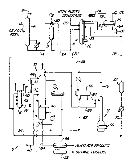
BRIEF DESCRIP~ )N~OF THE DRAWIN~
The Figure illustrates a combined operation for alkylate production.
2 o l he operation includes a selective hydrogenation zone 2 that produces a
monoolefinic feed, an allylation feed stripper 4 that receives monoolefins from
selective hydrogenation zone 2, along with a second isoparaffin ~eed stream and
provides an overhead fuel gas product and a combined feed to an allylation zone
6. The allylation zone has a reactor 8, an isostripper 10, for recovering products
2 5 frorn the reactor effluent, and an HF stApper 12 ~or recovering HF acid and delivering a recycle stream to the alkylation feed stripper 4.
DETAILED DESCRIPTION OF l~HE INVENTION
3 o ~he detailed description o this invention is given in the context of
an integrated process for the production of a C8 alkylate product from a feed
stream comprising C4 olefins and isobutane. Presentation of the invention in a
specific operational context is not meant to limit the invention to the particular
details disclosed herein. In order to simplify nomenslature the tenn isoparaffin as
used in the specification relates to the isoparaffins in lhe feedstock or the recycle
5 1~22~
associated with the HF alkylation reaction zone and alkylation feed stripper anddoes not refer to the product alkylate which is also an isoparaf~m.
Referring again to the Figure selective hydrogenation zone 2
receives an olefinic feed through line 14. The hydrocarbon feed entering the
5 selective hydrogen zone will consist primarily of butane, isobutane, and mixedbutenes, but will also contain butadienes. In addition trace amounts of C3
hydrocarbons may be present, however, the concentration of such materials
should be minimized by prior recovery in order to avoid HF contarnination
downstream. Typical olefin containing streams from which the feed stream can be
o derived are available from coking, steam cracking, and fluidized catalyst cracking
operations. These operations usually contain recovery facilities that can
accomplish the desired removal of and recovery of the C3-minus hydrocarbons
from the olefinic feed stream.
The Figure shows an olefin containing feed stream of mixed C3 and
5 C4 hydrocarbons from a fluidized catalytic cracking operation carried by line 13
and entering a fractionation zone comprising a depropanizer column 16. Column
16 is part of the product recovery facilities for the cracking operation. As used in
this specification, the term fractionation zone refers to the process equipment in
which a separation is performed and may include one or more fractionation
2 o columns as desired. Preferably, the fractionation columns are trayed columns.
The fractionation zones also comprise, to the extent required, such auxiliary
equipment as reboilers, overhead vapor condensors, and overhead receivers.
Depropanizer column 16 separates propane and propylene from the mixed feed
and withdraws these components as an overhead through line 18. Overhead 18 is
2 5 usually recovered as a product stream. Bottoms from depropanizer 16 enter line
14 and provide the previously described feed to selective hydrogenation zone 2.
Selective hydrogenation is used to convert at least a substantial
amount of the diolefinic hydrocarbons to monoolefinic hydrocarbons, which are
the desired olefinic components of the feed while at the same time reducing the
3 0 concentration of the undesired diolefinic hydrocarbons. 'I'he resulting lower
concentration of diolefinic hydrocarbons in the allylation zone results in a
reduced production of by-products including oligomers which lead to the
formation of deleterious compounds and fouling of the alkylation reactor.
~eduction of diolefins can also produce a decrease in the consumption of the HF
3 5 alkylation catalyst. Through the practice of this invention, the equipment
requirements for performing the selective hydrogenation can be minimized by
6 1~ZL~9
performing the hydrogenation step just upstream of a multifunction alkylation
feed stripper This provides a low cost and facile method of perforrning the
hydrogenation
In addition it is also known that the selective hydrogenation zone
beneficially isomerizes butene-1 to butene-2 Butene-2 is a more desired olefin in
the alkylation feed since it raises the octane of allylate products. Therefore,
selective hydrogenation has dual advantages for the alkylation zone.
The selective hydrogenation conditions employed in the
hydrogenation zone are preferably similar to that maintained in upstream
equipment such as depropanizer 16 Generally, the minimum pressure should be
sufficient to maintain the hydrocarbon reactants in liquid phase. A broad range of
suitable operating pressures, therefore, ex~ends from about 280 (4û) to about 7000
kPga (1000 psig), with a pressure between about 350 (S0) and 2000 IcPag (300
psig) being preferred. Reactions within hydrogenation zone favor relatively
moderate temperature conditions between about 25-C (77-F) and 250~C
(480-F). More preferably, the hydrogenation zone is maintained at a temperature
between about SO~C (120-F) and about 80-C (175-F). The liquid hourly space
velocity of the reactants through the selective hydrogenation zone should be
above 1Ø Preferably, it is above S.0 and more preferably it is between 5.0 and 35
2 o hr.~1. The optimum set of conditions will, of course, vary depending on such
factors as the composition of the feed stream, the activi~r and stability of thehydrogenation catalyst, and the operating conditions of upstream and downstream
equipmen~. Preferably, the selective hydrogenation zone 2 is operated at
conditions compatible with the bottoms conditions of depropanizer 16.
2 5 In addition to olefins entering the hydrogenation zone 2, a hydrogen
stream en~ers the zone through line 20. A significant amount of C3-minus
hydrocarbons, that are ultimately vented from the allylation feed stripper, are
contained in the hydrogen stream entering the selective hydrogenation zone. The
concentration of C3-minus hydrocarbons in the hydrogen stream may be as high
3 o as 35 mol%.
Another operating condition which may vary depending on catalyst
is the ratio of hydrogen to diolefinic hydrocarbons maintained with;n the selective
hydrogenation zone. Some catalysts, such as a palladium Ol1 alumina catalyst,
require a higher hydrogen concentration to achieve the desired degree of
3 5 hydrogenation. Therefore, with palladium catalysts, it may be desired lo operate
with a hydrogen to diolefinic hydrocarbon mole ratio of between 2:1 and 5:1.
'
With this catalyst, it was deterrnined that hydrogen concentrations above this
rar.ge resulted in the saturation of a significant amount of monoolefinic
bydrocarbons. This, of course, is undesirable as it reduces the yield of the process.
With a preferred nickel sulfide catalyst, as hereinafter described,
5 there should be less than 2.0 times the stoichiometric amount of hydrogen
required for the selective hydrogenation of the diolefinic hydrocarbons which are
present in the liquid phase process stream. Preferably, the mole ratio of hydrogen
to diolefinic hydrocarbons in the material entering the selectivè hydrogenation
zone is maintained between 1:1 and 1.8:1. In some instances, it may be desirable0 to operate with a less than stoichiometrically required amount of hydrogen, ~qth
mole ratios down to 0.75:1 being acceptable.
'rhe selective hydrogenation zone preferably comprises a single
fixed bed reactor containing a cylindrical bed of catalyst through which ~he
reactants move in a vertical direction. It is preferred that the reactants flow
15 upward through the reactor as this provides good mixing. l~e catalyst may be
present as pellets, spheres, extrudates, irregular shaped granules, etc. The prior
art suggests the use of a number of metals on the selective hydrogenation catalyst
including tungsten, palladium, silver, molybdenum, and nickel. Of these catalysts,
it is preferred that the active catalytic metal component present in the
2 o hydrogenation catalyst is either nickel or palladium, with nickçl being especially
preferred. When non-noble metals are employed, the catalyst should bave a high
concentration or loading of the active metal, with the metal component preferably
comprising over 10 wt.~o of the catalytic composite. More preferably, over 20
wt.% of the catalytic composite is metallic. It is very highly preferred that the
2 5 selective hydrogenation catalyst also comprises a sulfur component. The
preferred catalyst may, therefore, be described as a sulfided high iuckel catalyst.
The preparation of catalysts of this nature is described in U.S. Patent 3,919,341.
~he preferred selective hydrogenation catalyst has a lower sulfur concentration
than the catalyst described in this reference, with sulfur levels between about 0.1
3 o and 0.4 wt.% being preferred. The basic function of the sulfur component is
believed to be the attenuation of the hydrogenation activity of the nickel. It is
Icnown in the art that carbon monoxide may be passed into a selective
hydrogenation reactor for the purpose of moderating or attenuating the
hydrogenation reaction. The use of carbon rnonoxide and other such moderators
3 5 though not necessary, may be employed.
The selec~ive hydrogenation catalyst also comprises a support or
carrier material which should be relatively inert and refractory to the conditions
employed within the process. The support can be formed from a variety of porous
materials including various clays, diatomaceous earth, aluminas, ceramics,
5 attapulgus clay, and other synthetically prepared or naturally occurring silicates,
kaolin, kieselguhr, titania, alumina, crystalline aluminosilicates, and admixtures of
two or more of these materials. The especially preferred carrier material is an
alurllina. Of the aluminas, gamma-alulIuna is preferred. The carrier material orsupport may have an apparent bulk densi~,r of about 0.3 to about 0.8 g/cc, a
surface area of about 50 to about 550 m2/g, and a pore volume of between about
0.l and about 1.0 ml/g.
A portion of the total effluent from the selective hydrogenation
zone is recycled to the hydrogenation zone inlet. This recycle is used in order to
lower the concentration of diolefins and maintain liquid phase conditions when
5 the required hydrogen would otherwise exceed the hydrogen solubility of the
hydrocarbon stream.
The net effluent of the selective hydrogenation zone is a liquid
phase stream similar in nature to the liquid phase process stream rernoved from
the depropanizer but having a reduced concentration of diolefinic hydrocarbons
2 o and a corresponding increase in the concentration of monoolefinic hydrocarbons.
This effluent stream is passed into zone 4 and more specifically into allylationfeed stripping column 23, which is designed and operated to remove all
compounds which are more volatile than the lightest normal hydrocarbon which is
desired in the charge to the allylation section of the integrated process. ~hese2 5 lighter materials, in this case propane and lower boiling hydrocarbons, will be
concentrated into a net overhead stream which will comprise an admixture of
hydrogen and light hydrocarbons. One purpose of the alkylation feed stripper is
to prevent the entrance of light volatile materials into the alkylation zone where
they would present operational problems. The passage of light monoolefins into
3 o the allylation zone would also lead to the production of an increased amount of
undesired side products through alkylation and polymerization reactions.
An additional feed stream rich in C4 isoparaffins is charged to the
allylation feed stripper. Preferably, the isoparaffin feed stream will comprise high
purity isobutane which as shown by the Figure, is introduced into column 23 via
3 5 line 26. By high purity it is meant that this stream contains less than 2û~o higher
boiling hydrocarbons. In its preferred form, column 23 is a multitrayed colurnn
usually containing 40-50 trays. Preferably, the temperature and pressure of
column 23 will correspond with the conditions of select;ve hydrogenation effluent
at the inlet point of line 24. Column 23 also receives a recycle stream, hereinafter
described in more detail, from HF stripper l2 via a line 28. Recycle line 28 will
normally contain unconverted normal paraffins and isoparaffins. In the operationdepicted by the Figure, line 28 is rich in unconverted isobutane. VYhen used in
this specification the term rich means a stream having more than 50 mole % of
the named substanee.
Heavier components leave the bottoms portion of stripper zone 4
0 and provide a combined monoolefin, isoparaffin, and to a lesser extent paraffin,
feed for the alkylation zone 10. Preferably, the combined feed comprises
isobutane, normal butane, isobutene, and normal butenes which are recovered
from column 23 and charged to alkylation reactor 8.
Feed entering the alkylation reactor should be dry and have a low
sulfur content in order to reduce acid consumption and improve the ~quality of
alkylate products. In addition, water causes corrosion problems in the acid
en~ironment of the alkylation unit. Methods for treating feeds for sulfur removal
are well known. Standard practice for drying the feed has employed desiccant
dTying systems. As an alternative to the desiccant or other drying system, the
2 o alkylation feed stripper may also be used to dry the entire feed passing to the
allylation reactor. Designing the feed stripper to dry the allylation zone requires
approximately 20-25 trays between the feed withdrawal point and the lowermost
wet stream inlet point. Since the column will ordinarily require approximately 20-
25 trays between the inlet of line 24 and the bottoms of the column, drying
2 5 capacity is easily added to the alkylation feed s~ripper. Therefore, the use of the
alkylation feed stripper of ~his invention allows the elimination of drying
equipment ahead of the alkylation zone.
The allylation reaction is promoted by the presence of a mineral
acid catalyst, in this case hydrofluoric acid. The acid is maintained in a liquid
3 o phase containing a minimum of water. The maximum amount of water normally
allowed in the acid is about S wt.~o. When fresh acid is charged to a plant, it is
normally very dry and eontains about 0.5% water or less.
Alkylation conditions in general include a pressure sufficien~ to
maintain the hydrocarbons and acid in a liquid phase, with a general range being3 5 from about 140 kPag (20 psig) to about 3500 kPag (500 psig), and a more
preferred range being from 700 kPag ~lO0 psig) to about 1700 kPag (250 psig). It
is preferred that the pressure within the reactant-catalyst contacting vessel isapproximately lOS0 kPag
(150 psig~ and essentially "floats" on the pressure maintained in downstream
fractionation facilities. Although the allylation reaction may be performed at
temperatures from below -18~C (-4-F) to about 90~C (195-F), it is preferred to
operate the commercially prevalent isoparaffin-olefin alkylation process in the
range of from about 10-C (S0-F) to about 60-C (140~F), with 32-C (9û-lF) being
a representative and particularly preferred operating temperature.
Typically operating conditions in the alkylation zone include a high
0 ratio of the concentration of the paraffinic or other alkylatable material to the
concentration of the olefinic material in order to produce a high quality allylate
by encouraging monoalkylation instead of polymeri~ation. A broad range for this
ratio is from about 6 to about 20 with a pre~erred operating range being from 8 to
12. A second ratio which varies in competing allylation processes is the ratio of
the acid to the hydrocarbons in the total emulsion formed, that is, the ratio in the
material charged to the mixing zone or reaction point. This ratio may vary widely
from a high of about 10:1 to a low of about 0.2:1, but it is preferred that the
subject process is operated at an acid to hydrocarbon ratio of about 2:1.
There are a great number of ole~in-isopara~fin alkylation processes
2 o known to those skilled in the art. The great majority of these processes will
operate within the range of alkylation conditions set out above. They would,
however, have substantial differences in equipment and flow paths used in
performing the allylation. These variations are attempts to obtain optimum
~uality allylate by varying the method of contacting the monoolefin with the
isoparaffin. Since this reaction occurs very rapidly, and also because hydrofluoric
acid will catalyze the polymerization of the monoolefin, the standard alkylationmethod consists of first admixing acid-free streams of olefin and isoparaffin toform a reactant mixture which is then admixed with the hydrofluoric acid. In this
operation, a large mlmber of venturies or mixing nozzles are normally utilized to
3 o quickly disperse the olefin-containing stream into the acid-containing stream.
The resulting alkylation reaction is very exothermic and it is,
therefore, necessary to provide means to remove the heat of reaction. This is
normally done either by providing indirect heat-exchange means within the
reacting mL~ture or by cooling one of the reactant streams, normally the acid
stream, prior to passing it to the reaction zone. Mixing the acid and hydrocarbs~n
feed stream results in the formation of an emulsion, and it is pre~erred that this
emulsion be maintained by the continued agitation of the ernulsion since this
results in the removal of fluorides from the allylate and the improvement of theoctane number of the resulting alkylate. The main$enance of the emulsion is
normally effected by its passage through a mixer or soak zone comprising a vessel
5 having a number of internal obstructions which produce substantial turbulence as
the emulsion passes through them. The emulsion is then typically fed into some
type of settling vessel wherein a gravity separation of the emulsion is performed.
The acid phase is removed for recirculation7 and the recirculated acid may be
cooled to remove the heat of reaction. The hydrocarbon phase removed from the
0 rnixer settler is passed into the isos$ripper. I his hydrocarbon phase will comprise
mainly allylate and the excess isoparaffin which was fed to the allylation zone.Some processes do not utilize a soak zone at all and still others contact the
separated hydrocarbon phase with a regenerated high strength acid stream to aid
in defluorination. Further details on the design and operation of reaction vessels,
15 the overall operation of the allylation step, the regeneration of the preferred HF
catalyst, etc., may be obtained by reference to the previously cited references.The net hydrocarbonaceous effluent stream of the allylation zone is
passed into the isostripper 32 of a recovery section lO. This isostripper is
essentially the same as that normally associated with HF catalyst motor fuel
2 o allylation units. The isostripper recovers the C8 allylate and o$her C5-plushydrocarbons as a net bottoms stream 54 removed as the product of $he process.
When HF is used as the alky]ation catalyst, the bottoms stream contains a small
amount of isopentane produced in the alkylation zone. Some propane is also
produced in the allylation zone in this instance. Isobutane and normal butane are
25 withdrawn via line 34 from the isostripper for recycle to the alkylation zone.
Normal butane may be added or withdrawn from the isostripper as necessar, to
maintain vapor requirements for the alkylate product. When HF is u~lized as the
catalyst in the alkylation zone, fluoride compounds will normally be present in
these output streams. These streams should ihen be passed through a fluoride
3 o removal zone comprising an alumina treater and a caus~ic contacting zone.
Isobutane is withdrawn with the overhead from $he isostripper and may also be
withdrawn as a sidecut from the isostripper which is returned directly to the
allylation reactor.
Overhead is withdrawn from the isostripper via line 58 and is
35 condensed and charged to acid recovery i~acilities usually comprising an acid drum
~0 and an HF stripper 12. HF obtained from the recovery facilities is returned to
12
the allylation reactor via line 62 while the remaining, usually isobutane lich,
hydrocarbon stream from the HF stripper is charged via lines 27 and 28, in
accordance with this invention, to the alkylation ~eed stripper for light ends
removal.
In the embodiment of this invention depicted by the Figure,
allylation feed from line 30 is combined with an isobutane rich recycle stream
carried via line 34 from isostripper 32. The combined feed enters allylation
reactor 8 which comprises a shell and tube heat exchanger for circulatiIIg
relatively cool water through the tube side of the exchanger thereby maintainingo the reactor temperature below the desired leveL HF acid catalyst enters the shell
side of the reactor through a line 36. Reaction products and the commingled acidcatalyst are transferred to a settler vessel 38 by line 40. Settler 38 performs a
phase separation between a liquid hydrocarbon reactant and a liquid HF acid
stream. Acid flows out the bottom of the settler through line 42 which supplies
acid to line 36.
Allylation reaction products and unseparated HF acid are carried
overhead from settler 38 to isostripper 32 v~a line 44. Isostripper 32 is a trayed
fractionation column baving a reboiler 46 located in a lower mid portion.
Proceeding down the column from the input point of line 44 unreacted
2 o isoparaffins are withdrawn and condensed for re~ycle to the reactor as previously
mentioned via line 34. An inlet to isostripper 32 is provided next for adding
saturated butanes via line 48 if required for vapor pressure requirements of thealkylate product. If normal butane needs to be removed from the p}ocess stream,
it is withdrawn through line 50, caustic-treated in treater 52, and recovered as a
2 5 butane product. Alkylate product empties from isostripper 32 as a bottoms
stream through line 54 the contents of which receive caustic treatment in
treatment zone 56 before removal from the allylation zone. At the opposite end
of isostripper 32, mixed butanes and lighter hydrocarbons are taken overhead
through line 58, condensed and then col]ected in accumulator drum 60. A
3 o majori~ of the HF acid carried through line 58 drains into the boot of the
accumulator drum 60. Additional lHF catalyst is drained from the boot of drum 60and carried by line 62 back to line 36 or recycle to the reactor 8. Light
hydrocarbons from drum 60 pass back to isostripper 32 by lines 64 and 66 to
provide an overhead reflux. The remainder of the light hydrocarbons pass to HF
3 5 stripper 12 from line 64 to further reduce their HF acid concentration.
13 ~ 2~
HF stripper 12 provides a second separation of HF acid from the
light hydrocarbon~ A reboiler 68 pr~ides heat to the lower section of the HF
stripper for the separation~ Line 70 ca~ries HF acid overhead ~rom the stripper
and back to line 58 for remoYal of the HF acid from the accumulator drum and
5 stripper circuit by the boot of accumulator drum 60~ The light hydrocarbons taken
from the bottorn of the HF stripper by line 27 now having only a small
concentration of lHF acid vvhich is on the order of 1 wt~ ppm and which is further
reduced by caustic treating in zone 29.
As previously mentionedJ line 28 recycles unreacted butanes and
0 lighter hydrocarbons from the alkylation section to the allylation feed stripper.
The allylation feed stripper is designed to perform a cut between the overhead
and bottorns streams at about the boiling point of propane. Therefore, the
previously described isobutane-rich feed stream, taken ~rom the bottom of the
colurnn through line 30, will usually contain some propane. The reboiler 72
5 controls the bottom temperature of the column and provides heat as necessa~y.
At the upper end of the colurnn, propane and lighter gases are taken overhead byline 78, passed through a condenser 74, and collected in a vapor drum 76. A
portion of the condensed liquid returns to the column as a reflux by line 80.
All of the light gases including propane and propylene can be
2 o withdrawn from the top of the drum through a line 82 and removed from the
process~ Such an arrangement will be used primarily when the quantities of
propane and propylene in the overhead stream are relatively small. As the
quan~ity of propane and propylene in the overhead stream increases, it becomes
desirable to recover propylene and propane as a liquid product which is taken by25 a line 84 from the bottom of vapor drum 76~ When the quantities of propane and
propylene removed by stripper 23 becs)me relatively high, on the order of 3 wt.5?o
of the total input to the column, a sidecut of propylene and propane may be
withdrawn from the upper end of the column~ The Figure depicts this
arrangement by sidecut line 86 which withdraws a propylene and propane product
3 o from an upper tray level of column 23.
EXAMPLE
The following Example is presented to demonstrate the operation
35 of an alkylation feed stripper designed in accordance with this invention~ The
Example is based on engineering calculations and ~perational knowledge gained
14 ~L2~2~
from actual experience with similar processing equipment. The Example uses a
process arrangement substantially the same as that shown in Figure 1 with the
exception that there is no separate recovery of propylene or propane through line
84 or 86. Product compositions in units of Kmol/hr for various lines are provided
5 in the following Table.
Following the flow configuration and numbering system of the
Figure, a C3 and C4 olefin feed having a composition given in the Table is
introduced by line 13 into depropanizer column 16. Line 18 recovers a
propylene/propane product stream overhead having the composition given in the
lo Table. The remainder of the feed leaves the depropani~er column as a bottoms
stream and is transferred by line 14 at a temperature of 80-C (180-F) and a
pressure of 3100 kPag (450 psig) ~o the inlet of selective hydrogenation reactor 2
where it is combined with a hydrogen input stream through line 20 and a
dehydrogenation recycle stream. The composition of the hydrogen input stream
15 appears in the Table. The selective hydrogenation is carried out in the presence
of a sulfided high nicke] catalyst on an alumina support at a temperature of
80-90-C (180-190-F) and a pressure of 3100 kPag (450 psig). The Table lists the
composition of the selective hydrogenation product which is transferred by line 24
to allylation feed stripper 23. A high purity isobutane stream enters the
2 o alkylation stripper through line 26 and has the composition given in the Table.
The recycle stream frorn line 28 enters a column at a temperature of 75~(
(170-F) and a pressure of 2400 kPag (350 psig) and provides hydrocarbon inputs
as listed in the Table.
Bottoms stream 30 from the allylation feed stripper 4 proYides the
2 5 primary feed to HF allylation zone 6. These primary feed components h~ving the
composition listed in the Table and are reacted and separated in the alkylation
zone in a manner well known to those skilled in the art to provide an alkylate
product recovered from isostripper 10 through line 54 and the hereinbefore
described recycle stream which is taken from HF stripper 12 through line 28 and
3 o passed to feed stripper column 23.
Propane and lighter hydrocarbons are recovered oqerhead rom
column 23 $hrough line 18 cooled in condenser 74 and collected in drum 76.
~Reflux requirements for column 23 are met by withdrawing condensed liquid from
drum 76 and returning it to the top of column 23 by line 80. A net light gas stream
3 5 is withdrawn from the top of the colurnn through line 82 and has the composition
set forth in the Table. The contents of line 82 are sent to fuel gas.
22
TABLE
Line 13 18 20 24 26 28 30 82
H2 6.8 2.3 _ _ 2.3
Methane - - 1.4 1.4 - - - 1.4
Ethane - 3.6 1.0 1.0 - - - 1.0
Propylene272.7 27108 - ,9 - - - .9
Propane120.4 116~4 0.2 4.1 5.3 12.2 12.2 9.4
Isobutane144.7 3.6 - 141.1 161.2 73.3 375.6 .05
n-Butane 62.4 - - 62.4 8.5 8.6 79.5
Isobutene76.4 2.7 - 73.7 - - 73.7
Butene-1 76.4 .5 - 26.7 - ~ 26.7
Butene-2132.4 - - 186.9 - - 186.9
Butadiene4.5 - - - - - - -
C5 Hydrocarbons - - - .7 - .7 .8
LB M~l/Hr
~::
~: :