Sélection de la langue

Search

Sommaire du brevet 1292488 

Énoncé de désistement de responsabilité concernant l'information provenant de tiers

Une partie des informations de ce site Web a été fournie par des sources externes. Le gouvernement du Canada n'assume aucune responsabilité concernant la précision, l'actualité ou la fiabilité des informations fournies par les sources externes. Les utilisateurs qui désirent employer cette information devraient consulter directement la source des informations. Le contenu fourni par les sources externes n'est pas assujetti aux exigences sur les langues officielles, la protection des renseignements personnels et l'accessibilité.

Disponibilité de l'Abrégé et des Revendications

L'apparition de différences dans le texte et l'image des Revendications et de l'Abrégé dépend du moment auquel le document est publié. Les textes des Revendications et de l'Abrégé sont affichés :

  • lorsque la demande peut être examinée par le public;
  • lorsque le brevet est émis (délivrance).
(12) Brevet: (11) CA 1292488
(21) Numéro de la demande: 1292488
(54) Titre français: JOINT POUR TUYAUX
(54) Titre anglais: PIPE JOINT
Statut: Périmé et au-delà du délai pour l’annulation
Données bibliographiques
(51) Classification internationale des brevets (CIB):
  • F16L 21/025 (2006.01)
  • E21B 17/00 (2006.01)
  • F16L 09/02 (2006.01)
  • F16L 15/02 (2006.01)
  • F16L 15/04 (2006.01)
  • F16L 17/025 (2006.01)
  • F16L 17/10 (2006.01)
  • F16L 21/035 (2006.01)
(72) Inventeurs :
  • WESTBERG, ALVAR TORSTEN (Suède)
(73) Titulaires :
  • SANDVIK AB
(71) Demandeurs :
  • SANDVIK AB (Suède)
(74) Agent: GOWLING WLG (CANADA) LLP
(74) Co-agent:
(45) Délivré: 1991-11-26
(22) Date de dépôt: 1986-10-24
Licence disponible: S.O.
Cédé au domaine public: S.O.
(25) Langue des documents déposés: Anglais

Traité de coopération en matière de brevets (PCT): Non

(30) Données de priorité de la demande:
Numéro de la demande Pays / territoire Date
8505031-8 (Suède) 1985-10-25

Abrégés

Abrégé anglais


Abstract
A pipe joint for thin-walled tubes (13, 14) is provided for
transmission of water. The pipe joint includes a male
portion (11) and a female portion (12) both of which having
pressure cut threads (18, 21). At mounting thereof these
portions (11, 12) are threadably engaged so that a seal ring
(25) received in an annular extension (23) of the female
portion (12) is brought into engagement with a conical
portion (16) of said male portion (11) so as to provide
tightening of said pipe joint.

Revendications

Note : Les revendications sont présentées dans la langue officielle dans laquelle elles ont été soumises.


The embodiments of the invention in which an exclusive
right or privilege is claimed are defined as follows:
1. Pipe joint between a first thin-walled pipe and a
second thin-walled pipe, wherein:
a) said first thin-walled pipe has a firs-t pipe end and
said second thin-walled pipe has a second pipe end;
b) said first pipe end being adapted to be inserted into
and being rotated in relation to the second pipe end,
c) said first and second pipe ends being provided with
matching thread portions for mutual engagement;
d) the thread portion of said second pipe end having a
wall thickness which is substantially identical with
the wall thickness of said second pipe;
e) said second pipe end further having a conical portion
divergent in the direction axially away from the
second thin-walled pipe, said conical portion being
located axially outwardly relative to the thread
portion of the second pipe end and being conically
convergent towards the thread portion of the second
pipe end;
f) the thread portion of said first pipe end having a
wall thickness substantially identical with the wall
thickness of said first pipe;
g) said first pipe end further including an axially inner
portion disposed axially inwardly relative to the
thread portion of the first pipe end, said axially
inner portion being conically convergent towards the
thread portion of the first pipe end;
h) a seal ring being arranged to be received in an
annular extension provided in said second pipe end
near and axially inwardly of said conical portion but
axially outwardly of the thread portion of said second
pipe end;
i) said seal ring being arranged so as to sealingly
engage the interior surface of said annular extension
and the outer surface of said axially inner portion of
said first pipe end.
-6-

2. Pipe joint as defined in claim 1, wherein the
radially outermost portion of said annular extension defines
the largest diameter of the pipe joint.
3. Pipe joint as defined in one of claims 1, or 2,
wherein the general diameter of said joint is larger than the
diameter of the tubes.
4. Pipe joint as defined in claim 3, wherein general
diameter of said joint is 1.05-1.2 times larger than the
diameter of said tubes.
5. Pipe joint as defined in one of claims 1 or 2,
wherein said annular extension is substantially U-shaped in
cross-section, the interior surface of said extension being
smooth and disposed substantially parallel with the centre
line of the pipe joint.
6. Pipe joint as defined in claim 1 or claim 2,
wherein said annular extension is substantially V-shaped in
cross-section.
7. Pipe joint as defined in claim 1 or claim 2 wherein
said annular extension is substantially W-shaped in cross-section.
-7-

Description

Note : Les descriptions sont présentées dans la langue officielle dans laquelle elles ont été soumises.

8i~3
PIPE JOINT
The present invention relates to a pipe joint between a
first pipe with small wall thickness and a second pipe with
small wall thickness.
Until now, deep wells have been lined with galvanized
carbon steel screw joint pipes connected to each other by
means of internally threaded couplings. The sealing function
has been provided by flax or linseed oil. These pipes are
heavy to handle since the depth of the well can be as much as
50 m and the wall of the pipe is thick. The thick pipe wall
is needed in order to make room for the cut thread. Further,
these screw joints have easily become disengaged due to the
percussion and vibrations that occur during pumping.
Another well known pipe coupling for thin-walled pipes
consists of a male portion and a female portion with matching
threaded portions. The male portion has a conical
enlargement axially inside the thread which is arranged to
elastically force the cylindrical end portion radially
out-wards so as to make the coupliny tightened during the
final part of the in-screwing movement. This type of pipe
coupling must be threadably engaged by means of machine force
in order to provide sufficient force to the pipes so that an
elastic deformation of the end portion of the female portion
can occur. This end portion is also sensible to percussion.
It is an object of the present invention to provide an
improved pipe joint that can be mounted manually without
tools.
It is another object of the invention to provide a pipe
joint that is effectively tightened also after small
engagement forces.
It is another ob;ect of the invention to provide a pipe
joint that is rigid but easy to handle.
In general terms, the invention provides a pipe joint
between a first thin-walled pipe and a second thin-walled
pipe, wherein: a) said first thin-walled pipe has a first
pipe end and said second thin-walled pipe has a second pipe
@~
~ ~ii

-- 2 --
end; b) said ~irst pipe end being adapted to be inserted into
and being ro-tated in relation to the second pipe end; c) said
first and second pipe ends being provided with matching
thread portions for mutual engagement; d) the thread portion
of said second pipe end having a wall thickness which is
substantially identical with the wall thickness of said
second pipe; e) said second pipe end ~urther having a conical
portion divergent in the direction axially away from the
second thin-walled pipe, said conical portion being located
axially outwardly relative to the thread portion of the
second pipe end and being conically convergent towards the
thread portion of the second pipe end; f) the thread portion
of said first pipe end having a wall thickness substantially
identical with the wall thickness of said first pipe; g) said
first pipe end further including an axially inner portion
disposed axially inwardly relative to the thread portion of
the first pipe end, said axially inner portion being
conically convergent towards the thread portion of the first
pipe end; h) a seal ring being arranged to be received in an
annular extension provided in said second pipe end near and
axially inwardly of said conical portion but axially
outwardly of the thread portion of said second pipe end; i)
said seal ring being arranged so as to sealingly engage the
interior surface of said annular extension and the outer
surface of said axially inner portion of said first pipe end.
Other objects and features of the invention will become
apparent from the following description of the invention,
with reference to the attached drawings. In the drawings:
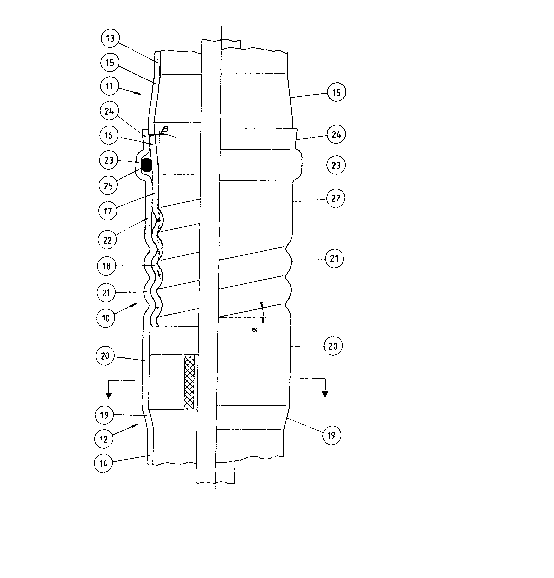
Fig. 1 is a longitudinal quarter section of a pipe joint
in accordance with the present invention,
Fig. 2 is a section of a pipe end portion according to
Fig.
Fi.g. 3 is a partial longitudinal section of an
alternative embodiment of the invention,
Fig. ~ is a partial longitudinal section of another
alternative embodiment of the invention,
Fig. 5 is a section along the line V-V in Fig. 1.

~2~
-- 3 --
Referring now to Fig. 1 a pipe joint is shown generally
at 10 including a male pipe portion 11 and a female pipe
portion 12. ~he portions 11 and 12 are also referred to as a
"first" and "second" pipe end, respectively. The thread
profiles of these pipe portions are preferably
pressure-turned at the end of thin walled pipes 13 and 14
respectively. The pipes are cylindrical in shape and
arranged for the purpose of transmitting fluid therethrough.
Referring now to Fig. 1 the following is a detailed
description of the male portion 11 from its upper to its
lower portion. The pipe 13 is conically enlarged at 15
followed by a conical section 16 which converges towards a
aylindrical section 17 with substantially the ~ame diameter
as the pipe 13. The section 17 is terminated by a thread
portion 18 including pressure-turned threads which means that
the thickness of the threads iæ substantially identical with
the thi.ckness of the pipe 13. Referring again to Fig. 1 the
following is a detailed description of the female portion 12
from its lower to its upper portion. The pipe 14 is conically
enlarged at 19 followed by a cylindrical portion 20 the
diameter of which is 5-15% larger than the diameter of the
pipe 1~. This cylindrical section 20 is followed by a thread
portion 21 with pressure-cut threads whereby the general
diameter of said portion 21 exceeds the diameter of the pipe
14. The threaded portion 21 is followed by another
cylindrical section 22 the diameter of which is
substantially identical with the diameter of the section 20.
The section 20 is followed by an annular extension 23
having U-shaped cross-section. The outer diameter of said
annular extension 23 i.s 10-30% larger than the diameter of
the pipe 1~. This extension 23 is followed by a conically
enlarged portion 2~. The main purpose of providing said
enlarged port:Lon 2~ is to facilitate entering the male
portion 11 on to the female portion 12. The extension 23 is
arranged to receive a seal ring 25, preferably made of
nitrile rubber. The interior surface 23a of said extenæion
23 is mainly flat and disposed parallel with the centre line

Z~L8~3
-- 4 --
CL of the pipe joint. The cross-section of said extension
can also have other alternative shapes. V-shaped or
W-shaped as shown in E~ig. 2 and Fig. 3 respectively.
At the engagement the pipe 13 i9 entered into the female
portlon 12. The female portion 12 is oriented upwards and
supported by a fork-stopper or similar means abutted against
the conical portion 19 or the extension 23. Hence, it is
preferable to have the pipe string arranged with the female
portion oriented upwards in order to prevent it from falling
down into the well during mounting and dismounting.
When the thinner male portion 11 is arranged in line
with the wider female portion 12 and is displaced downwards
the male portion will be centrally arranged towards the
conical portion 2~ of the female portion whereby the threads
18 will become engaged with the threads 21 until the male
portion is stopped. At manual rotation of the male portion
in relation to the female portion the male portion will be
drawn into the female portion due to the cooperation between
said threaded portions. When the conical section 16 of the
male portion enters the seal ring 25 and the conical
enlargement 24 a tight coupling arrangement is achieved
between said male and female portions. The surfaces of said
threaded portions should be hard and smooth. The female
thread portion will be squeezed and locked between the flank
portion of the male thread and the conical portion 16 of the
male thread. Each flank has an angle lnalination at 2-6- in
rslation to a normal to the aentre line CL, and the
inclination B on the conical sectlon 16 ls between 3 and 10'
in relation to the centre line CL. The thin wall thickness
will give a large elasticity whlch promotes a good locking of
the portions to each other. The rounded thread sections will
make them less susceptible to damages than threads that are
being cut.
The pipe joint has been successfully subjected to test
pressing at a pressure of 250 bar by internally applied water
pressure without any water leakage. The pipe joint according
to the invention has also been subjected to tensile testing
~,~

~Z9~ 38
-- 5
whereby the threads were dismounted after reaching stresses
of seven ton. The tubes used for these tests were made of
ferritic-austenitic stainless steel and had dimension 42.4 x
1.2 mm. A pipe joint made of stainless steel tubes with
dimensions 38 x 2 mm was successfully subjected to ates
pressure exceeding 600 bar by internally applied water
pressure without any water leakage.
The thread that is forced into threaded engagement and
the annular extension 23 will cooperate in a manner that
stiffens or reinforces the pipe ends. Generally the diameter
of the pipe joint is 5-20% larger than the diameter of the
pipes 13, 14. The above related procedure is reversed at
dismounting so that no tooling is needed.
Fig. 5 shows a section along the line V-V in Fig. 1. A
sleeve 26 is arranged in abutment with the interior surface
of cylindrical section 20. The sleeve 26 is arranged to
guide a piston 27 centrally received in the pipes. The
piston 27 is arranged in cooperation with a pump arranged at
the lower end of the pipe string (not shown). The sleeve has
a central hole and four arms that are bent and the ends of
which abuts with and engages with the interior surface of the
cylindrical section 20.
The inventi.on provides a pipe joint which can be mounted
and dismounted without tooling assistanae. This pipe joint
has a good tightening ability and high strength.
~L

Dessin représentatif
Une figure unique qui représente un dessin illustrant l'invention.
États administratifs

2024-08-01 : Dans le cadre de la transition vers les Brevets de nouvelle génération (BNG), la base de données sur les brevets canadiens (BDBC) contient désormais un Historique d'événement plus détaillé, qui reproduit le Journal des événements de notre nouvelle solution interne.

Veuillez noter que les événements débutant par « Inactive : » se réfèrent à des événements qui ne sont plus utilisés dans notre nouvelle solution interne.

Pour une meilleure compréhension de l'état de la demande ou brevet qui figure sur cette page, la rubrique Mise en garde , et les descriptions de Brevet , Historique d'événement , Taxes périodiques et Historique des paiements devraient être consultées.

Historique d'événement

Description Date
Inactive : CIB de MCD 2006-03-11
Le délai pour l'annulation est expiré 2005-11-28
Lettre envoyée 2004-11-26
Accordé par délivrance 1991-11-26

Historique d'abandonnement

Il n'y a pas d'historique d'abandonnement

Historique des taxes

Type de taxes Anniversaire Échéance Date payée
TM (catégorie 1, 6e anniv.) - générale 1997-11-26 1997-10-17
TM (catégorie 1, 7e anniv.) - générale 1998-11-26 1998-10-20
TM (catégorie 1, 8e anniv.) - générale 1999-11-26 1999-10-18
TM (catégorie 1, 9e anniv.) - générale 2000-11-27 2000-10-18
TM (catégorie 1, 10e anniv.) - générale 2001-11-26 2001-10-17
TM (catégorie 1, 11e anniv.) - générale 2002-11-26 2002-10-17
TM (catégorie 1, 12e anniv.) - générale 2003-11-26 2003-10-16
Titulaires au dossier

Les titulaires actuels et antérieures au dossier sont affichés en ordre alphabétique.

Titulaires actuels au dossier
SANDVIK AB
Titulaires antérieures au dossier
ALVAR TORSTEN WESTBERG
Les propriétaires antérieurs qui ne figurent pas dans la liste des « Propriétaires au dossier » apparaîtront dans d'autres documents au dossier.
Documents

Pour visionner les fichiers sélectionnés, entrer le code reCAPTCHA :


Pour visualiser une image, cliquer sur un lien dans la colonne description du document. Pour télécharger l'image (les images), cliquer l'une ou plusieurs cases à cocher dans la première colonne et ensuite cliquer sur le bouton "Télécharger sélection en format PDF (archive Zip)" ou le bouton "Télécharger sélection (en un fichier PDF fusionné)".

Liste des documents de brevet publiés et non publiés sur la BDBC .

Si vous avez des difficultés à accéder au contenu, veuillez communiquer avec le Centre de services à la clientèle au 1-866-997-1936, ou envoyer un courriel au Centre de service à la clientèle de l'OPIC.


Description du
Document 
Date
(aaaa-mm-jj) 
Nombre de pages   Taille de l'image (Ko) 
Abrégé 1993-11-08 1 13
Revendications 1993-11-08 2 65
Dessins 1993-11-08 1 25
Description 1993-11-08 5 222
Dessin représentatif 2001-07-19 1 13
Avis concernant la taxe de maintien 2005-01-23 1 173
Taxes 1996-10-17 1 72
Taxes 1995-10-19 1 58
Taxes 1994-10-19 1 70
Taxes 1993-10-17 1 55