Note : Les descriptions sont présentées dans la langue officielle dans laquelle elles ont été soumises.
a~2 g~
-- 1 ~
"MOBILE SUSPENDED SCAFFOLD"
BACKGROUND OF THE INVENTION
This invention relates to a mobile suspended scaf-
fold arrangement particularly of a type which includes a
support portion which can run on rails on the roof of a
building with a scaffold portion carried on the support por-
tion and suspended over an edge of the roof to lie along
side a wall of the building for carrying out building opera-
tions on the wall and in the area of the junction between
the wall and the roof.
Various arrangements of scaffold arrangement of this
type have previously been proposed and in a search carried
out in relation to the present invention the following United
States patents were revealed: 3,854,550 - 2,639,950 - 1,054,376
3,245,355 - 3,066,757 - 3,454,818 - 4,074,789 and 3,282,377.
Of these prior patents probablythemost relevant are
United States patent 3,854,550 (Shingler) issued in 1974 and
United States patent 4,074,789 (Warren et al) issued in 1978.
The second of these patents shows a device which is arranged
for rolling movement along the Z-shaped purlins of a building
under construction. This patent shows a rolling arrangement
on the purlins which includes what the inventor calls "force
rollers" which run along the underside surface of a purlin
to prevent the device toppling from the roof. Such an arrange-
ment has a significant disadvantage in that it is difficult
to apply to the rails or purlins and furthermore it is not
2~
suitable for use with rails or purlins of a different shape
without significant modification.
The Shingler patent shows a device which runs
on specifically mounted planks and uses a counterweight
arrangement. However the construction of the wheel arrangement
is not satisfactory for use on rails of different shapes
and the unit is limited therefore in it use.
There remains therefore a requirement for a mobile
scaffold of this type which is designed particularly but
not exclusively for use in the assembly of steel buildings.
This provides an improved connection between
the scaffold portion and the support portion so that the
scaffold portion is held rigid as opposed to the conventional
swining cable supported scaffold portions of the prior
art. This arrangement enables the device to operate most
effectively for its intended purpose of supporting an operative
suitably at a position adjacent the wall or junction between
the wall and the roof so that he can operate upon the part
for cladding or other operations as reguired while being
supported in a manner which allows movements and forces
to be applied without the scaffold portion swinging about.
According to the present invention, therefore,
the~e is provided a rnobile suspended scaffold system comprising
a support portion for running along a roof of a building
~Z~Z~89
and a scaffold portion arranged to be suspended from said
support portion along a side wall of the building, said
support portion comprising a first wheel assembly for running
along a first rail adjacent an edge of the roof, a second
wheel assembly for running along a second rail parallel
to the first and spaced from the edge of the roof, frame
means interconnecting the first and second wheel assemblies
and forming a platform therewith, two booms extending upwardly
and outwardly from the platform to respective upper support
positions above the first wheel assembly, spaced outwardly
of the roof edge and spaced from one another longitudinally
of the rails, two lower support members projecting outwardly
from the platform to respective lower support positions
spaced vertically below the respective upper support portions,
said scaffold portion comprising a pair of rigid suspension
members at positions spaced therealong longitudinally of
said rails, upper connecting means connecting said suspension
members to respective ones of the booms at the upper support
positions, and lower connecting means connecting the suspension
members to the respective lower support members at the
lower support positions, the upper and lower connecting
means co-acting to hold the suspension members rigid relative
to said support portion.
Each of the wheel assemblies may comprise first
and second support wheels spaced longitudinally of the
respective rail, with each mounted for rotation about an
~2~Z~
axis parallel to the roo~ and having a periphery arranged
to run on an upper surface parallel to the roo~ of the
respective rail. First and second guide wheels are spaced
longitudinally of the respective rail and are mounted for
rotation about axes at right angles to the roof. Each
guide wheel has a periphery arranged to engage a surface
at right angles to the roof o~ the respective rail, with
edges of the periphery of the guide wheels being spaced
on opposed sides of a plane containing the points o~ contact
between the periphery of the support wheels and the upper
surface of the rail.
A counterweight may be provided on the support
portion spaced frorn the first wheel assembly on the side
thereof remote from the scaffold portion and arranged to
provide sufficient movement about the first wheel assembly
to maintain the support wheels of the second wheel assembly
in contact with the second rail.
The counterweight cooperates with the previously
described wheel arrangement so that the support portion
can readily be mounted upon the roof of the building and
is readily adjustable to suit different rail or purlin
arrangements. The wheel arrangements using the support
wheels and the guide wheels arranged at right angles thereto
enable the device to run on various shapes of rail without
the necessity for modification or adjustment.
The support portion may be composed of a pair
48~31
of first wheel assemblies, a pair of second wheel assemblies
and a pair of frame means each interconnecting a respective
one of the pairs of first and second wheel assemblies thus
forming two separate dollies movable separately along the
roof on the first and second rails. Means are provided
for connecting the first and second dollies to form an
integral support portion for the scaffold portion.
This arrangement provides an improved construction
of the support portion which enables it to operate not
only as a support for the scaffold portion but also to
form a pair of dollies which can be used in carrying roof
panels for use in the cladding of the roof in the conventional
steel building construction. Preferably the dollies are
formed by splitting the support portion in the form of
a platform into two separate halves in a direction at right
angles to the rails so that two havles can continue to
run on the rails and each half can be used to carry various
pieces of equipment used in the roof cladding process.
With the foregoing in view, and other advantages
as will become apparent to those s]cilled in the art to
which this invention relates as this specification proceeds,
the invention is herein described by reference to the accompany-
ing drawings forming a part hereof, which includes a description
of the best mode known to the applicant and of the preferred
embodiment of the principles of the present invention,
in which:
- 6 - ~ ~92~9
DESCRIPTION OF THE DRAWINGS
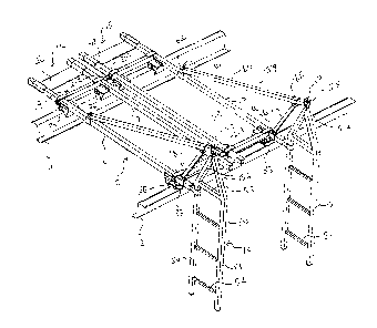
Figure 1 is an isometric view of the whole of
the scaffold arrangement mounted upon the roof of a building
with the roof being shown only as a pair of rails~
Figure 2 is a side elevational view of the apparatus
of Figure 1 showing the rails mounted upon a building structure.
Figure 3 is a side elevational view on an enlarged
scale of the second wheel assembly of the apparatus of
Figures 1 and 2.
Figure 4 is an isometric view on an enlarged
scale of the second wheel assembly also shown in Figure
3.
Figure 5 is an isometric view similar to that
of Figure 4 showing the first or front wheel assembly of
the apparatus of Figures 1 and 2.
Figure 6 is an isometric view similar to that
of
~ --\
- 7 - ~ ~9~4~
Figure 1 on an enlarged scale showing a single one of the
dollies forming part of the support portion of the apparatus
of Figure 1.
In the drawings like characters of reference indi-
cate corresponding parts in the different figures.
DETAILED DESCRIPTION
Basically, this device is an apparatus used to aid
in the application of metal cladding onto prefabricated metal
structures, although it can readily be used on other types
of buildings as well. The device is a mobile and portable
framework which rides along the roof structural members of
the building while supporting, during part of its operation,
a platform for workers.
The apparatus comprises generally a support portion
indicated at 10 which can be mounted upon the roof purlins
11 and 12 and a scaffold portion generally indicated at 13
which is suspended from the support portions so as to depend
over the side of the building beyond the edge of the roof as
best shown in Figure 2.
The support portion comprises a pair of dolley mem-
bers 14 and 15 which are effectively identical and symmetrical
about a central axis lying at right angle to the rails 11
and 12. Each of the dollies comprises a frame structure in
the form of a pair of straight parallel beams 16 and 17
which are connected to a front wheel assembly 18 and a rear
wheel assembly 19.
- 8 ~ 89
The most basic component of the apparatus is the
wheel assembly or castor assembly illustrated in most detail
in Figures 3, 4 and 5. Each wheel assembly comprises a
rigid axle 20 which extends parallel to and above the rail
and is formed by a tubular beam. The beam 20 carries on each
end a loop portion 21 formed by an upper bracket 22 and a
lower bracket 23 which define between them an opening for a
respective one of the frame beams 16 and 17. The brackets
22 and 23 terminate in spaced flanges 24 which can be clamped
together by a bolt so as to clamp the brackets around the
beam 16, 17 to retain the wheel assembly at a required posi-
tion along the length of the respective beam 16, 17.
The lower bracket 23 projects outwardly to one side
thereof as indicated at 25 to define a platform for resting
against another side of the respective beam 16, 17. The
platform 25 has upstanding side walls 26 which act to confine
the beam 16, 17 and retain the axle 20 properly at right
angles to the beam and to prevent any twisting of the axle
20 about an axis longitudinally thereof relative to the beams
16 and 17.
A plate 27 extends downwardly from the underside
of the platform 25 and is supported by triangular webs 28 and
29 at both ends thereof. The plate 27 thus defines a 9Up-
port for a guide wheel 30 which is carried in a yoke 31 a
base 32 of which is clamped to the plate 27. A support wheel
33 is mounted upon a yoke 34 which also includes a base plate
- 9 -
35 attached directly to the underside of the bracket 23.
Thus the axle 36 of the wheel 33 lies urgently horizontal
direction with a periphery of the wheel 33 arranged to run
on an upper surface 37 of the purlin 11. The axle 38 of the
wheel 30 is arranged at right angles to the axle 36 that is
generally vertically so that the periphery of the wheel 30
lies in a substantial vertical plane for running against a
vertical side surface 39 of the purlin 11. The upper and
lower edges 40 and 41 of the wheel 30 are arranged so that
they lie in planes spaced on either side of the lowermost
point of the periphery of the wheel 33 so that the periphery
of the wheel 30 necessarily runs against an edge of the sur-
face 37 whether that edge be part of the purlin which is Z-
shaped as shown or part of another structure for example a
rectangular tube, an eye beam or the like.
The support wheel 33 rides along the horizontal
member or purlin of the building structure and thereby sup-
ports and mobilizes the apparatus. The keeper or guide wheel
is positioned so as to restrict movement of the apparatus to
horizontally traverse. The right angle configuration of the
support wheeL on the guide wheel allows the castor assembly
to cooperate with virtually any structural shape.
The rigid axle member 20 may be of any suitable
length but in one preferred arrangement is of the order of
three feet in length which provides a usuable dolley for sup-
porting for example roof cladding. The length of the axle 20
1 0 -- ~ ;2r ~
may be adjustable if required. It will be noted that the
guide wheels 33 of one of the wheel assemblies are arranged
on the same side of the support wheels so that the drive
wheels run along the same edge of the roof structural member
and can simply be placed against that edge by lowering the
wheel assembly onto the respective rail.
The loop members 21 by their design when secured
or tightened by the bolts (not shown) will maintain the beam
16 and 17 in a fixed position. Each individual wheel assem-
bly may be reversed relative to the beam 16 and 17. However
under normal conditions the base frame unit or dolley would
be assembled as illustrated with the front wheel assembly
arranged so as to restrict motion toward the exterior of the
building and the rear wheel assembly arranged so as to re-
trict movement toward the interior of the building. By the
nature of the beams and wheel assemblies as previously de-
scribed, the dolley thus forms a rigid rectangular shape
which can be adjusted in length so that the unit becomes
effectively locked between these structural members with
which it cooperates, while transverse mobility is unrestrict-
ed.
The front wheel assemby and the rear wheel assembly
are effectively identical in their construction and operation.
They do differ however in that each incorporates unique fea-
tures which distinguish their purpose and position in the
base assembly. The rear wheel assembly is fitted with a
safety hook 41 which is positioned on the axle 20 and is
bolted thereto at a point midway along its length that is
between the two support wheels 33. Tile hook member includes
a downwardly projecting portion and a rearwardly projecting
hook 42 which extends beneath the upper surface 37 of the
purlin 11. The depth of the downward projection can be ad-
justable by adjusting the position of bolting of the upper
portion to the axle 20. In addition the hook can be adjust-
ed towards or away from the axle. In this manner the safety
hook may be positioned so that it is immediately adjacent to
but spaced from the structural member and particularly the
upper surface 37 thereof. Under normal conditions the safety
hook does not in any way affect the operation or movement of
the base frame assembly. Its sole purpose is to offer an
additional margin of safety by restricting upward vertical
motion at the rear extreme of the support frame assembly so
as to prevent the whole frame assembly from toppling from the
building by plvotal movement about the front wheel assembly.
The front wheel assembly includes brake mechanisms
schematically indicated at 43 ln the form of wedge members
which can be inserted between the upper surface of the sup-
port wheel 33 and the yoke 34. Thus manual pivoting of a
rack 44 about the axle 34 of the wheel 33 causes a wedge mem-
ber 45 carried thereby to be inserted into that area to cause
jamming of the wheel 33 to halt movement of the unit along
the rails.
` - ~
~z~z~
- 12 -
In addition the wedge members 45 operate effective-
ly as a brake in a situation where the rails are mounted at
the gable ends of the building so the rails are inclined to
the horizontal. The whole unit is thus prevented from runn-
ing down the gable end by the operation of the wedge members
45 which halt the wheels untill the wedge members are moved
manually to allow the unit to roll along the rail as required
by the operative.
The weight of the scaffold portion 13 and the
operatives thereon together with any tools they may be using
is counterbalanced about an axis defined by the front wheel
assemblies by a counterweight mounted at a rearwardmost end
of the beam 16 and 17 and indicated at 46. The counterweight
is calculated to be of a suitable mass bearing in mind the
very much greater mechanical advantage so that the unit can
accommodate the required amount with of course a suitable
safety factor.
It will be appreciated therefore that the support
member constituted by the dollies 14 and 15 connected together
can simply be lowered onto the rails without any necessity
for adjustment of wheels or connection of wheels beneath rail
portions and can simply sit on the rails for movement there-
along without any possibility of twisting or pivoting.
The two dollies 14 and 15 are connected together
simply by straps 47 and 48 which connect into the bolts clamp-
ing the loop members indicated at 21A and 21B which lie ad-
-
- 13 - ~ 4~9
jacent at the center between the two dollies.
The dollies can be separated simply by disconnect-
ing the straps 47 and 48 from one of the associated loop
members so that the dollies can be moved separately along the
rails 11 and 12. The utilization of two or more base frames
or dollies cooperated in a single unit affords many advantages.
The overall size of the device when expanded offers por-
tionally greater working area. The expanded configuration
allows for a greater degree of stability. A subsequent employ-
ment of additional support wheels provides a greater loading
capacity as well as a more effective load distribution. The
subsequent employment of extra guide wheels also improves the
stability and thus the effectiveness of the device.
Because each base frame unit or dolley is identical,
any number of these units may be linked together in a modular
fashion to accommodate any situation. Conversely the number
of units can be reduced as required.
When the dollies are separated they may be employed
individually or in corporation with one another to provide
a variety of services. Basically they become portable and
mobile working surfaces easily positioned anywhere on the
building roof structure which provide a expanded accessibility
for the placement of component members. The dollies may also
be used to transport roof cladding along the roof plane.
The adjustability and reversible capabilities of the wheel
assemblies ensure that the base frames can be employed vir-
' -
l~Z~39
- 14 -
tually anywhere on the roof regardless of purlin shape, size
or spacing.
As shown best in Figures 1 and 2 the scaffold por-
tion 13 comprises a pair of rigid laddler-type supports 50
and 51 which have transverse rungs 52 for supporting planks
or flooring upon which an operative can stand. Each ladder
support includes a pair of rigid uprights 53, 5~, a transverse
strut 55 and inwardly inclined support beams 56 which connect
at an upper apex. A loop 57 is welded at the apex for attach-
ment over a hook 58 of the support frame. The length of the
loop 57 may be adjustable by providing a number of separate
loops or by clamping the loops to the apex in such a manner
that it may be movable relative thereto. This allows the
height of the respective ladder support to be adjusted rela-
tive to the support frame. This is particularly useful when
the support frame is mounted on rails at the gable end of the
building since the inclination of the gable end can be accom-
modated by adjusting the height of the apex of one of the
ladder supports so as to retain the flooring connecting the
rungs 52 at a horizontal level.
The hook 58 is mounted on a boom assembly generally
indicated at 59 carried on the beams 16 and 17 of the support
frame. Each boom 59 comprises an elongate beam 60 which has
a bracket 61 at a lower end relative to which the beam 60 can
pivot~ The bracket 61 is of the type which includes three
sides which surround the beam 17 so that when loose it can
- 15 - ~Z~z4~3
slide along the beam 17 but can be clamped into frictional
engagement therewith by a bolt which connects together flanges
62 of the bracket. The flanges 62 receive therebetween an
ear 63 projecting outwardly from the end of the beam 60 so
that when loose the beam 60 can slide along the beam 17 and
can pivot relative thereto.
The beam 60 is supported at an angle relative to
the beam 17 by a strut 64 which carries at an upper end a
bracket 65 and at a lower end a bracket 66 both of which are
similar in construction to the bracket 61. Thus the angle
and position of the beam 60 can be adjusted by sliding each
of the brackets 61, 65 and 66 and then can be locked into
place by tightening the respective bolts to the clamp the
brackets around the respective beam. The hook 58 is welded
to the end of the beam 60 so as to project outwardly there-
from and to define a cup for receiving the loop 57 of the
respective ladder support. A transverse pin 67 can be mount-
ed in place to close the hook 58 after the loop is properly
located to prevent any possibility of disengagement between
the hook and loop.
rrhe ladder support is also attached to the beam 17
by way of a strut 68 which is slidable within an open end of
the beam 17 at the end thereof adjacent the edge of the roof.
The position of the strut 68 within the beam 17 can be adjust-
ed and locked by any suitable mechanism. Attached to an outer
end of the beam 68 is a bracket 69 of the same construction
~z~
- 16 -
as the bracket 61 and which clamps around one leg of the
ladder support. Thus the ladder support is held rigidly at
two separate points by the support structure on the roof so
that it is preven-ted from swinging or twisting relative to
the hook 58.
In an initial assembly of the boom structure on the
roof support, the clamps are still loose and do not retrict
adjustment of the boom assembly. As the boom assembly is
essentially a triangular configuration, it offers the greatest
degree of structural integrity. With the clamps unsecured,
the three sides of the triangle formed are completely adjust-
able with respect to boom angle. In addition the entire boom
may be allowed to move along the length of the beam 17. The
projection of the boom past the building wall is more or less
established by the positioning of the rear of the boom and
the corresponding clamp. Sufficient pressure may be applied
by tightening the structural fastener of the clamp so as to
maintain the clamp in a fixed position relative to the base
rail while still allowing the boom to pivot on that bolt.
Desirable boom angle is achieved by adjusting the boom strut.
It should be noted that the boom assembly 59 is
positioned at the outermost beam 16 of the dolley 14 and the
outermost beam 17 of the dolley 15 thus spacing the ladder
supports as far apart as possible which in the example shown
will be of the order of seven feet. Further spacing can be
achieved by introducing further dollies which are then clamp-
1~9~89
- 17 -
ed together as previously described. In addition if only a
single person is required to work on the scaffold, the boom
can be moved to the beam 17 of the dolley 14 so that the
scaffold portion is supported on a single one of the dollies
providing a working width between the ladder supports of the
order of three feet.
Cross braces (not shown) can be connected between
the boom 59 adjacent the hook 58 and the beam 16 or 17 of
the other boom of the pair. This provides an X-brace retain-
ing the booms at the required spacing to prevent any twisting
of the whole unit.
The boom assembly utilizes a corresponding base
rail in order to accomplish its structural effectiveness. The
fittings on all component members have been designed to be
interchangeable. Therefore any boom or boom strut may be
used in conjunction with any base rail to effectively accom-
plish a boom assembly. For complete rigidity of the unit,
employment of X-bracing (not shown) can be provided between
the ladder supports interconnecting the outer legs thereof.
The scaffold portion illustrated is a basic unit designed to
be used on all structures. It is of sufficient length to
provide average access for workers in the vertical plane.
As buildings can vary in height or elevation, it follows that
the ladder supports must be equiped to accommodate such var-
iations. Secondary ladder supports may be added to the de-
scribed unit in order to expand the overall length thereof
~2~8~
- 18 -
in a modular fashion.
The device in its fully assembled form is basical-
ly designed to expedite the cladding process with regard to
the side walls of prefabricated metal buildings. The horizon-
tal lay of the eave member purlins allows the mechanism to
roll from side to side in a relative stable manner. The end
walls or gable ends of most prefabricated buildings have a
slope built into shed water. By convention this slope is
either 1:12 or ~:12 as a standard, although other slopes are
often engineered to suit special situations. Because the
roof structuralsor purlins are situated so that their length
is at right angles to the end walls and because these purlins
step down from the horizontal in accordance with the corres-
ponding roof pitch, the roof structurals are not suitable to
maintain the operation of the device as described. However,
the wheel assemblies are designed to cooperate with virtual-
ly any structural shape. There it is no great task to temporarily
attach suitable rails to the roof structure parallel to the
end wall plane supported by the standard building purlins.
As the wheel assemblies are completely adjustable relative
to the frame, any convenient spacing of the temporary rails
may be used provided of course that they remain parallel to
one another.
Because these devices utilizes a counterweight sys-
tem to maintain stability in the horizontal plane, it would
seem logical that a mechanism could also be used for procedures
- 19 ~
related to walls after the roof cladding has been placed.
There are numerous functions which can only be initiated after
the roof and walls are installed. Placement of eave trim and/or
gutter is the most obvious example. In most instances the
cladding procedures beginswith the wall cladding placement
immediately followed by placement of the roof. However it
is not unusual for the customer to request that the roof be
placed first and then the walls so that he can perform cer-
tain interior functions under the shelter, or that the walls
be left until certain machinery can be moved into the build-
ing before the walls are closed in. The device has therefore
been designed with these variations in mind. The flexibility
of the apparatus provided by the specific design of the wheel
assemblies, the separation of the unit into two separate
dollies and the various adjustabilities allow the unit to be
used in various different circumstances in this general field.
In addition the rigid support of the hangers or ladder supports
provide a very safe working environment for the operatives
and allows them to apply forces to the building and to move
on the flooring without danger of the unit moving or toppling.
Since varlous modifications can be made in my in-
vention as hereinabove described, and many apparently dif-
ferent embodiments of same made within the spirit and scope
of the claims without departing from such spirit and scope,
it is intended that all matter contained in the accompany-
ing specification shall be interpreted as illustrative only
and not in a limiting sense.