Note : Les descriptions sont présentées dans la langue officielle dans laquelle elles ont été soumises.
1~9ZBS,3Z
The present inventiorl related to a corltinously
variable automotive transmissiorl comprising a fluid torque
converter and a contirluously variable transmissiorl mecharlism
employing a V belt.
There are several knowrl contirluously variable
automotive transmissions in which engine power is transmitted
through a V-belt contirlously variable transmissiorl mechanism,
either through a fluid torque converter or clutchs and
through a speed reducer gear tran for drivirlg vehicle wheels,
such as U.S. Patents 4,548,100, 4,559,850, 4,605,112 and
4,624,153 and the two Japanese Patent Publications noted
below.
Japanese Laid-Open Patent Publication No. 55-63051
discloses a contirluously variable automotive transmissior
wherein the turbine shaft of a fluid torque converter is
disposed coaxially with the driver shaft of a V-belt contirl-
uously variable transmissiorl mechanism, and the driven shaft
thereof is coupled to either a gear mechanism includirlg two
parallel gear trains for selecting forward and rearward gear
positions or a forward/rearward-gear-position selecting
mechanism includirlg a clutch and planetary gear mechanism
which are arranged parallel to each other.
Another contirluously variable automotive trans-
mission disclosed irl Japanese Laid-Open Patent Publication
- 1 - ~
lZ9~892 60724-1782
No. 57-192666 includes a forward/rearward-gear-pcsition
selecting gear mechanism disposed coaxially with the turbine
shaft of a fluid torque converter.
With the conventional arrangements, since the turbine
shaft and the driver shaft are positioned in coaxial relation
to each other and the forward/rearward-gear-position selecting
mechanism (which may comprise two gear trains or a clutch and a
planetary gear mechanism) is coupled to either the driven shaft
or the driver shaft, the conventional continuously variable
transmissions are of axially large dlmensions, and contain a
large number of gears. Further, the drive torque is
transmitted through the V-belt continuously variable
transmlssion mechanism not only when the automobile is moving
forwardly, but also when it is moving rearwardly.
SUMMARY OF THE INVENTION
It is an object of the present invention to provide a
continuously variable automotive transmission which has a
reduced number of gears for selecting forward and rearward gear
positlons, is of smaller axial dimensions and of a reduced
size, and increases the service life of a V-belt used in a V-
belt continuously variable transmission mechanism by nok
transmittin~ torque through the V-belt continuously variable
transmission mechanism when the automobile is running
rearwardly.
According to the present invention, the above object
can be achieved by a continuously variable automotive
transmission for transmitting power from an engine to
automotive wheels that includes a fluid torque converter
adapted to be connected to the engine and having a turbine
shaft, driver gear means fixedly mounted on the turbine shaft,
and a fixed ratio reverse and continuously variable ratio
B 2
`-` 1292~39Z
60724-1782
forward transmission mechanism. The continuously variable
transmission mechanism comprises a driver pulley mounted on a
driver shaft rotatably mounted parallel to the turbine shaft, a
driven pulley mounted on a driven shaft rotatably mounted
parallel to the turbine shaft and driver shaft, a V-belt
trained around the driver and driven pulleys, the driver pulley
and driven pulley having means for varying the drive ratio
therebetween transmitted through the V-belt, a forwarcl gear
rotatably mounted on the driver shaft and held in mesh with the
driver gear means, a forward clutch mounted on the driver shaft
for selectively connecting and disconnecting the forward gear
to and from the driver shaft, a reverse gear rotatably mounted
on the driven shaft and held in mesh with the driver gear means
through an idler gear, and a reverse clutch mounted on the
drlven shaft for selectively connectiny and disconnecting the
reverse gear to and from the driven shaft.
The driver gear means may comprise a single driver
gear meshing with the forward and idler gears or two driver
gears meshing with the forward and idler gears, respectively.
The above and other objects, features and advantages
of the present lnvention will become more apparent from the
following description when taken in conjunction with the
accompanying drawings in which preferred embodiments of the
present invention are shown by way of illustrative example.
BRIEF DESCRIPTION OF THE DRAWINGS
Figure 1 is a schematic view of the power train of an
automobile incorporating a con~inuously variable transmission
according to an embodiment of the present invention; and
B
lZ9~B92 181/170
FIG. 2 is a schematic view of the power train of an
automobile incorporatirlg a contirluously variable transmissior
according to another embodiment of the present inverltiorl.
DESCRIPTION OF THE PREFERRED EMBODIMENTS
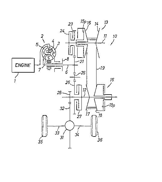
FIG. 1 schematically shows a contirluously variable
transmissiorl according to an embodiment of the present
inverltiorl, the corltinuously variable transmissiorl being
incorporated in the power train of an automobile having an
engirle E. The engirle E is mounted such that its crar!kshaft
is directed in the transverse direction of the automo~ile.
The contirluously variable transmissiorl generally includes a
fluid torque converter 2 and a V-belt contirluously variable
transmissiorl 10. Engirle power from the engirle 1 is applied
to a pump 3 of the fluid torque converter 2 which has a direct
coupling clutch 4. When the pump 3 is rotated by the engirle
power, a turbine 5 is rotated to rotate a turbirle shaft 6
about its own axis. The fluid torque converter 2 also has a
stator 7 includirlg a stator shaft 8.
The turbine shaft 6 is fixed at its righthand end
(as shown in FIG.l ) to a driver gear 21. The V-belt contirl-
uously variable transmissiorl 10 has a driver shaft 11 and a
driven shaft 12 which extended parallel to the turbine shaft 6.
The driver shaft 11 supports a forward gear 23 rotatably
mounted on its lefthand end and meshing with the driver gear
21, and also supports a hydraulically operated multiple-disc
forward clutch 24 on the lefthand side of the forward gear 23.
A driver pulley 13 is mounted on the driver shaft 11 on a
righthand portion thereof. The driver pulley 13 comprises a
` ~Z~Z~392 181/170
fixed pulley member 14 on the righthand erld of the driver
shaft 11 and a movable pulley member 15 positioned orl the
lefthand side of arld spaced from the fixed pulley member 14.
The movable pulley member 15 is movable on and along the
driver shaft 11 toward and away from the fixed pulley member
14 by means of a piStorl 15p on the driver shaft 11.
The driven shaft 12 supports orl its rightharld portion
a driv~rl pulley 16 comprisirlg a fixed pulley member 17 positiorled
on the righthand portion of the driverl shaft 12 and a movable
pulley member 18 located on the righthand side of the fixed
pulley member 17 and movable toward and away from the fixed
pulley 17 by means of a piston 18p. A metallic V belt 19 is
B trained around the driver pulley 13 and the driven pulley ~.
The power can be trarlsmitted from the driver shaft 11 to the
driven shaft 12 through the driver pulley 13, the V belt 19,
and the driverl pulley 16 at a corltinuously variable ratio
responsive to operation of the pistorls 15p, 18p.
A reverse gear 26 is rotatably mounted on the driven
shaft 12 at its lefthand portiorl. The reverse gear 26 meshes
with an idler gear 25 held in mesh with the driver gear 21. A
hydraulically operated multiple-disc reverse clutch 27 i5
disposed on the driverl shaft 12 rightwardly of the reverse
gear 26. A final speed reducer gear 28 is fixedly mounted or
the driven shaft 12 at its lefthand erld leftwardly of the
reverse gear 26. The final speed reducer gear 28 is held in
mesh with a ring gear 32 of a differential 31 which is opera-
tively coupled to drive axles 33, 34 conrlected respectively
to automobile wheels 35, 36.
Wherl the automobile is moved in a forward directiorl,
the forward clutch 24 is engaged of ON, the reverse clutch 27
12~ Z 181/170
is disengaged or OFF, and engirle power from the engirle 1
is trarlsmitted as follows: The engiIIe power is first
applied through the fluid torque converter 2 to the turbine
shaft 6 and then through the driver gear 21, the forward
gear 23 and the forward clutch 24 to the driver shaft 11.
The power is then transmitted from the driver pulley 13
through the V belt 19 and the driven pulley 16 to the driven
shaft 12, fro~ which it is transmitted through the final
speed reducer gear 28, the ring gear 32, the differential
31, and the drive axles 33, 34 to the respective wheels 35,
36. The engirle power can thus be transmitted to the wheels
35, 36 at a contirluously variable transmissiorl ratio. Since
the reverse clutch 27 is disengaged at this time, the reverse
gear 26 is freely rotated on the driven shaft 12 in the direction
opposite to the diretion in which the driven shaft 12 is rotated
about its own axis.
For moving the automobile in the reverse direction,
the forward clutch 24 is disengaged or OFF and the reverse
p O~er`
clutch 27 is erlgaged or ON. The erlgine ~K~ is transmitted
from the driver gear 21 through the idler gear 25 to the
reverse gear 26 at a constarlt gear ratio thereof, from which
it is trarlsmitted via the reverse clutch 27 to the driven
shaft 12. At this time, because of the interverlirlg idler gear
25, the driven shaft 12 is rotated in the opposite direction
to that in which it is rotated wherl the automobile runs in
the forward direction. The wheels 35, 36 are rlow rotated irl
the reverse direction. Although the driver shaft 11 is also
rotated in the opposite direction by the driven pulley 16,
the V belt 19, and the driver pulley 13 at this time, no torque
-- 6 --
181/170
lZ~392
is trarlsmitted through the V belt 19 since the forward clutch
24 is disengaged and the forward gear 23 is freely rotated
oll the driver shaft 11.
The turbine shaft 6, the driver shaft 11, and the
driverl shaft 12 are arranged parallel to each other. The
turbine shaft is operatively conrlected to the driver shaft
11 through the driver gear 21 and the forward gear 23, or
to the driven shaft 12 through the driver gear 21, the
idler gear 25, and the reverse gear 26. Since the various
B gears 21,23,25, 26 may be disposed substantially in rad-ial
alignmerlt, the rlumber of gears required can be reduced
and the axial dimerlsiorl of the transmissiorl can be reduced.
The forward gear 23 orl the driver shaft 11 is disposed
between the driver pulley 13 and the forward clutch 24, and the
reverse clutch 27 on the driven shaft 12 is disposed between
the criven pulley 16 and the reverse gear 26. Thus, the forward
and reverse clutches 24, 27 are positioned on on each side of the
train of the gears 21, 23, 25, 26. The final speed reducer gear
28 fixedly mourlted on the driverl shaft 12 is on one side of the
gear train which is opposite to the driven pulley 16. The
m e ~n loer
movable pulley ~cr 15 of the driver pulley 13 is located
close to the forward gear 23, and the fixed pulley member 17 of
the driven pulley is located close to the reverse clutch 27.
v~nirn;~es
This arrangemerlt mir ~ i2ed the axial dimensiorl of the contirluously
variable transmissiorl.
FIG. 2 shows a contirluously variable transmissiorl
according to another embodiment of the present inventiorl. The
contirluously variable transmissiorl shown irl FIG. 2 ls different
from that of FIG. 1 orlly irl that two ~uxtaposed driver gears 21,
22 are mourlted on the righthand erld of the turbirle shaft 6, the
lZ9Z~92 181/170
lefthand driver gear 21 meshing with the forward gear 23 and
the righthand driver gear 22 meshing with the idler gear 25.
Since the driver gear 22 is separate from the driver gear
21 meshing with the forward gear 23, the speed reduction
f~e /~
ratio of the reverse gear train carlrf~4el'cy-be selected
irrespective of the forward gear train.
Although certain preferred embodiments have been
showrl and described, it should ~e understood that many
ch~v1,3 es
~d arld modifications may be made therein without
departing from the scope of the appended claims.