Sélection de la langue

Search

Sommaire du brevet 1293101 

Énoncé de désistement de responsabilité concernant l'information provenant de tiers

Une partie des informations de ce site Web a été fournie par des sources externes. Le gouvernement du Canada n'assume aucune responsabilité concernant la précision, l'actualité ou la fiabilité des informations fournies par les sources externes. Les utilisateurs qui désirent employer cette information devraient consulter directement la source des informations. Le contenu fourni par les sources externes n'est pas assujetti aux exigences sur les langues officielles, la protection des renseignements personnels et l'accessibilité.

Disponibilité de l'Abrégé et des Revendications

L'apparition de différences dans le texte et l'image des Revendications et de l'Abrégé dépend du moment auquel le document est publié. Les textes des Revendications et de l'Abrégé sont affichés :

  • lorsque la demande peut être examinée par le public;
  • lorsque le brevet est émis (délivrance).
(12) Brevet: (11) CA 1293101
(21) Numéro de la demande: 1293101
(54) Titre français: UTILISATION D'UN CHAMP MAGNETIQUE EN COULEE CONTINU
(54) Titre anglais: USE OF MAGNETIC FIELD IN CONTINUOUS CASTING
Statut: Périmé et au-delà du délai pour l’annulation
Données bibliographiques
(51) Classification internationale des brevets (CIB):
  • B22D 11/04 (2006.01)
  • B22D 11/10 (2006.01)
  • B22D 27/02 (2006.01)
(72) Inventeurs :
  • MULCAHY, JOSEPH A. (Canada)
(73) Titulaires :
  • J. MULCAHY ENTERPRISES INCORPORATED
(71) Demandeurs :
  • J. MULCAHY ENTERPRISES INCORPORATED (Canada)
(74) Agent: MARKS & CLERK
(74) Co-agent:
(45) Délivré: 1991-12-17
(22) Date de dépôt: 1987-09-18
Licence disponible: S.O.
Cédé au domaine public: S.O.
(25) Langue des documents déposés: Anglais

Traité de coopération en matière de brevets (PCT): Non

(30) Données de priorité de la demande: S.O.

Abrégés

Abrégé anglais


Abstract of the Disclosure
The continuous casting of heavy metals in a
magnetic field is improved by using a magnetic field in
the form of essentially uniform flux lines closely
parallel to the casting surface. The instability
experienced with the liquid meniscus is minimized and
higher intensity fields, permitting casting of heavier
metals, can be achieved.

Revendications

Note : Les revendications sont présentées dans la langue officielle dans laquelle elles ont été soumises.


The embodiments of the invention in which an exclusive
property or privilege is claimed are defined as follows:
1. In a method of continuous casting of a heavy metal
wherein said heavy metal in the molten state is
subjected to a magnetic field and is cooled to a solid
state, the improvement which comprises providing said
magnetic field in the form of essentially uniform flux
lines closely parallel to an upper casting surface and
having a physical height corresponding to the physical
height of the metal in its molten state.
2. The method of claim .1 wherein said magnetic field
is provided by magnetic coil which has a reactance which
is linear throughout its height.
3. The method of claim 2 wherein said magnetic coil is
partially enclosed within an iron core.
4. In a continuous casting mold having an
electromagnet for applying a magnetic field to a molten
heavy metal, the improvement wherein said magnetic field
is provided by a magnetic coil which has a reactance
which is linear throughout its height and which has a
physical height corresponding substantially to the
intended height of molten metal in said mold and thereby
produces a magnetic field in the form of essentially
uniform flux lines closely parallel to an upper casting
surface of molten metal cast in said mold.
5. The mold of claim 4 wherein said magnetic coil is
enclosed within an iron core except in the portion
intended to face the molten metal.

Description

Note : Les descriptions sont présentées dans la langue officielle dans laquelle elles ont été soumises.

3~
~SE OF MAGNETIC_FIELD LN CDNIINI~US CASTING
The present invention relates to the continuous
casting of heavy metals.
Ths use of magnetic fields in the casting of h~avy
metals, such as aluminum is well known. In one known
process, called "electromagnetic casting", an
alternating magnetic field forces the aluminum away Prom
the walls of the casting pit, so that no contact is
provided between the metal and the mold during cooling,
which produces aluminum ingots with smoother, cleaner
surfaces.
This techni~ue also has been applied to continuous
casting wherein the conventional chill mold is replaced
by a magnetic field which exerts a radial force on the
molten metal. When the metal solidifies, it forms a
column, which is lowered continuously at the same time
as molten metal is supplied to the mold.
Problems arise, however, in the commercial
application of such casting techniques. In particular,
a rolling action often is experienced at the meniscus of
the melt as a result of unbalanced magnetic forces
acting on this area, which leads to surface
imper~ections in the cooled metal. In add:Ltion, metals
heavier than aluminum, such as copper and iron, are
di~icult or impossible to process by such techniques,
because of the much higher magnetic fields involved.
The present invention is directed to improvements
in the continuous casting of heavy metals in the
presence of a magnetic field which avoid the problems of
the prior art discussed above and which enable a broader
range of metals to be cast, including copper and iron.
In the present invention, a magnetic field in the
form of essentially uniform flux lines closely parallel
to the casting surface is employed. A magnetic field of
this type minimizes the unbalanced forces which cause
the menisclls to roll in the prior art. In addition,
this type of magnetic ~ield permits the higher magnetic
`j intensities required by heavier metals to ~e achieved.

o~
The essentially unifo~n flux lines of the magnetic
field are achieved using a magnetic coil which has a
reactance which is linear thrsughout its height. This
result may be achieved by partially enclosing the
magnetic coil within an inner core.
Another drawback of the prior art lies in the fact
that, with the existing magnetic coil structure, the
bottom of the liquid meniscus needs to be maintained at
approximately the centre of the magnetic coil. The
improved magnetic coil arrangement o~ the. present
invention enables a considerably-greater portion of the
coil to be employed.
Accordingly, in one aspect of the present
invention, there is provicled a method of continuous
casting o~ a heavy metal wherein the heavy metal in the
molten state is subjected to a magnetic field and is
cooled to a æolid state, the improvement which comprises
providing the magnetic field in the form of essentially
uniform flux lines closely parallel to an upper casting
sur~ace and having a physical height correspondiny to
~he physical height of the metal in its molten state.
Further, in a~other aspect of the invention, there
is provided a continuous casting mold having an
electromagnet for applying a magnetic field to a molten
heavy metal, the improvement wherein the magnetic field
is provided by a magnetic coil which has a reactance
which is linear throughout its height and which has a
physical height corresponding substantially to the
intended height of molten metal in the mold and thereby
produces a magnetic field in the form of essentially
uniform flux lines closely parallel to an upper casting
of molten metal cast in the mold.
The invention is dascribed further, by way of
illustration with reference to the accompanying
drawings, in which:
Figure 1 is a sectional view of part of an existing
continuous casting mold;
Figure 2 is a sectional view of part of a
~'

31~1
continuous casting mold provided in accordance with one
embodiment of the invention; and
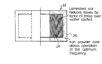
Figure 3 is a partial sect:ional view of an
electromagnetic coil use~ul in the continuous casting
device of Figure 2.
Re~erring to Figure 1, there is illustrated a
continuous casting mold 10 wherein a strand of aluminum
12 is formed from a ca~t molten aluminum. A magnetic
coil 14 surrounding the strand 12 exerts a magnetic
field on the strand 12 and maintains the strand 12 away
from the mold wall.
The liquid mekal cools to ~orm a solid metal which
then is conveyed continuously downwardly and out o~ the
mold. The liquid metal 16 initially cast i5 enclosed by
the magnetic field and is on top of khe soli.dified metal
18. The liquid metal 16 forms a meniscus 20. As can be
seen, the magnetic field 22 to which the molten metal is
subjected is uneven and this leads to instability in the
meniscus 20.
Referring now to Figure 2, a continuous casting
machine 10' is provided in accordance with one
embodiment of the invention. In this instance, the
liquid metal 16' is surrounded by an electromagnetic
coil 14' of particular construction, more particularly
seen in Figure 3. The coil 14' produces a magnetic
~ield 22' in the form o~ essentially uniform flux lines
closely parallel to the castiny surface 20'. The
uniformity of the strength of the magnetic field through
the height of the liquid metal 16' ensures stability of
the meniscus 20'.
As may be seen by comparison between Figures 1 and
2, the usable height of the coil 1~' extends for the
height of the liquid metal 16' while in the case of coil
14, the centre line of the coil corresponds to the
interface between the liquid metal 16 and the solid
metal 18~
The ability to shape the magnetic lines in
accordance with this invention enables differences in
hydrostatic pressure in the liquid metal 16~ to be
.~ ,

lr~
accommodated and permitting the correct shape to be
maintained during solidification and solidified metal
skin formation. In addition, magnetic fields of higher
intensity may be achieved, thereby permitting heavier
metals to be processed.
As seen in Figure 3, the electromagnetic coil 14'
is an annular structure of inside diameter sufficient to
permit the coil to surround the metal strand 12'.
laminated coil 24 is accommodated within an iron powder
core 26.
Although generally the procedure of the present
invention is used to form metal strands of circular
cross section, by appropriate alteration of the
configuration of the coil, any other cross-sectional
shape of metal strand, such as square or rectangular,
may be produced.
In summary of this disclosure, the present
invention provides improvements in the casting of heavy
metal in a magnetic field, which produce a more stable
meniscus and hence improved product appearance and
which enables heavier metals to be cast. Modifications
are possi~le within the scope of this invention.

Dessin représentatif
Une figure unique qui représente un dessin illustrant l'invention.
États administratifs

2024-08-01 : Dans le cadre de la transition vers les Brevets de nouvelle génération (BNG), la base de données sur les brevets canadiens (BDBC) contient désormais un Historique d'événement plus détaillé, qui reproduit le Journal des événements de notre nouvelle solution interne.

Veuillez noter que les événements débutant par « Inactive : » se réfèrent à des événements qui ne sont plus utilisés dans notre nouvelle solution interne.

Pour une meilleure compréhension de l'état de la demande ou brevet qui figure sur cette page, la rubrique Mise en garde , et les descriptions de Brevet , Historique d'événement , Taxes périodiques et Historique des paiements devraient être consultées.

Historique d'événement

Description Date
Le délai pour l'annulation est expiré 2001-12-17
Lettre envoyée 2000-12-18
Inactive : TME en retard traitée 1998-12-01
Lettre envoyée 1997-12-17
Accordé par délivrance 1991-12-17

Historique d'abandonnement

Il n'y a pas d'historique d'abandonnement

Historique des taxes

Type de taxes Anniversaire Échéance Date payée
TM (catégorie 1, 7e anniv.) - petite 1998-12-17 1998-12-01
Annulation de la péremption réputée 1998-12-17 1998-12-01
TM (catégorie 1, 6e anniv.) - petite 1997-12-17 1998-12-01
TM (catégorie 1, 8e anniv.) - petite 1999-12-17 1999-12-16
Titulaires au dossier

Les titulaires actuels et antérieures au dossier sont affichés en ordre alphabétique.

Titulaires actuels au dossier
J. MULCAHY ENTERPRISES INCORPORATED
Titulaires antérieures au dossier
JOSEPH A. MULCAHY
Les propriétaires antérieurs qui ne figurent pas dans la liste des « Propriétaires au dossier » apparaîtront dans d'autres documents au dossier.
Documents

Pour visionner les fichiers sélectionnés, entrer le code reCAPTCHA :


Pour visualiser une image, cliquer sur un lien dans la colonne description du document. Pour télécharger l'image (les images), cliquer l'une ou plusieurs cases à cocher dans la première colonne et ensuite cliquer sur le bouton "Télécharger sélection en format PDF (archive Zip)" ou le bouton "Télécharger sélection (en un fichier PDF fusionné)".

Liste des documents de brevet publiés et non publiés sur la BDBC .

Si vous avez des difficultés à accéder au contenu, veuillez communiquer avec le Centre de services à la clientèle au 1-866-997-1936, ou envoyer un courriel au Centre de service à la clientèle de l'OPIC.


Description du
Document 
Date
(aaaa-mm-jj) 
Nombre de pages   Taille de l'image (Ko) 
Revendications 1993-11-16 1 38
Abrégé 1993-11-16 1 23
Page couverture 1993-11-16 1 13
Dessins 1993-11-16 1 26
Description 1993-11-16 4 176
Dessin représentatif 2000-07-13 1 13
Avis concernant la taxe de maintien 1998-01-28 1 179
Quittance d'un paiement en retard 1998-12-14 1 170
Avis concernant la taxe de maintien 2001-01-15 1 178
Taxes 1996-07-19 1 36
Taxes 1995-07-24 1 38
Taxes 1994-07-29 1 53
Taxes 1993-07-16 1 30