Note : Les descriptions sont présentées dans la langue officielle dans laquelle elles ont été soumises.
~.~3~1?iS
--1--
PROCESS AND APPARATUS FOR
USE WITH PRESS~IZED REACTORS
This invention concerns a method for introdu
cing fluid feeds to pressurized reactors. This invention
also concerns an apparatus capable of effecting such
introduction. In one of the more specific aspects,
the method and apparatus of this invention concern
the manufacture of H2 and CO containing gaseous pro-
ducts, e.g., synthesis gas, reducing gas and fuel
gas, by the high pressure partial oxidation of car-
bonaceous slurries.
Proc~sses for and apparatuses used in the
pressurized partial oxidation of carbonaceous slurries
are both well known in the art. See, for example,
: U.S. Patents 4,113,445; 4,353,712; and 4,443,230.
In most instances, the carbonaceous slurry and an
oxygen-containing gas are fed to the reactor which
is above the temperature, generally about 2500F
(1370C) of the devolitalization products of the
.
32,475-F 1-
--2--
carbonaceous slurry in the presence of oxygen. Bring-
ing the reactor up to the autoignition temperature can
be achieved by at least two methods. In one of the
methods, a simple pre-heat burner is affixed, in a non-
-airtight manner, to the reactor's burner port. This
pre-heat burner introduces a fuel gas, e.g., methane,
into the reactor to produce a flame sufficient to warm
the reactor to a temperature of about 2000 to 2500F
(1090 to 1370C) at a rate which does not do harm to
the reactor refractory material. Generally, this rate
is from about 40F/hr to about 80F/hr (4.4C/hr to
27C/hr). During this pre-heat stage, the reactor
is kept at ambient pressure or slightly below. The
less than ambient pressure is desirable as it causes
air to enter the reactor through the non-air-tight
connection between the pre-heater and the reactor,
which air is th~n available for use in combusting
the fuel gas. After the desired pre-heat temperature
is achieved, the pre-heat burner is removed from the
reactor and is replaced by the process burner. This
replacement should occur as quickly as possi~le as the
reactor will be cooling down during the replacement time.
Cool downs to a temperature as low as 1800F (980C) are
not uncommon. I~ the reactor temperature is still within
the acceptable temperature range, the carbonacoues slurry
and the oxygen containing gas, with or without a
temperature moderator, are fed through the process
burner to achieve partial oxidation of the slurry.
When the slurry is initially fed, the oYygen-contain-
ing gas feed has to be set to briny the reaction zonequickly to a temperature above the liquid temperature
of the slag produced in the reaction zone. This quick
heating causes thermal shock to the reactor refractory
material.
32,475-F -2-
--3--
If, however, the reactor temperature is too
low, then the pre-heater must be replaced back into
service. This replacement is not desirable as process
time is lost and additional labor expense is realized
with the replacement duplication.
The other of the two methods for bringing
up the reactor temperature to wi-thin the desirable
range entails the use of a process burner only; see,
for example, the burner disclosed in U.S. Patent
4,353,712. This type of process burner provides con-
duits for selective and contemporaneous feeding of
carbonaceous slurry, oxygen-containing gas, fuel gas
and/or temperature moderators. When the process burner
is used for pre-heating the reactor, the burner feeds
the oxygen-containing gas and the fuel gas in the
proper proportions to achieve complete combustion.
After the reactor temperature is within the desired
range, the fuel gas can either be replaced completely
by the carbonaceous slurry or co-fed with the slurry.
When the co feeding mode is used, generally the fuel
gas feed is reduced so that there will only be partial
oxidation occurring. Co-eeding is usually used when
initially introducing the carbonaceous slurry to the
reactor and when maintaining reactor temperature until
process conditions can be equilibrated for the carbona-
ceous slurry/oxygen-containing gas feed mode of opera-
tion.
While the process burner only method of
operation does not suffer from the loss in process time
and the additional labor expenses of the pre-heat
burner/process burner method, it is nGt without its
32,475-F -3-
--4--
own drawbacks. When using the process burner only
method, -the maintenance of flame stability under both
ambient pressure-complete oxidation and high pressure-
-partial-oxidation conditions, which are, respectively,
used in the pre-heat and the carbonaceous slurry partial
oxidation steps of the process, is difficult and can
result in lowering of process reliability.
Some in the synthesis gas industry have
proposed using the combination of a pre-heat burner
and a process burner in which the latter is capable
of providing a selective contemporaneous feed of
carbonaceous slurry, oxygen-containing gas, fuel
gas and/or temperature moderators. While this
combination may still entail the loss of process
time and the realization of labor costs associated
with the preheat burner replacement by ~he process
burner, the selective contemporaneous feed feature
of the process burner is used to reduce the before-
-discussed thermal shock to the reactor refractory
material. The reduction in thermal shock is achieved
by bringing the reactor temperature from its cooled-
down temperature back up to the desired temperature with
the fuel gas feed and then feeding the carbonaceous
slurry contemporaneously with the fuel gas. The car-
bonaceous slurry feed is started off at a low leveland is increased while the fuel gas feed is gradually
decreased to 0 in accordance with the need by the
reactor for heat to maintain its desired temperature.
By initially feeding the carbo~aceous slurry at a
low rate, there is less of the slurry liquid to heat
and vaporize and thus a minimization of reactor tem-
perature dip. Further, during the initial period of
32,475~F -4-
--5--
carbonaceous slurry feed, the continued feeding of
the fuel gas results in the addition of heat to the
reactor. The fuel gas is combus-ted under partial
oxidation conditions so that there is little con~
tamination by, for example, CO2 of the gas produc-t.
For a process burner to be useful in the
just-described procedure, it must be capable of
providing to the reactor, in an efficient manner,
both the carbonaceous slurry and the fuel gas feeds
in conjunction with their respective oxygen-containing
gas feeds. Efficiency demands that the carbonaceous
slurry be evenly dispersed in the oxygen-containing
gas and be in a highly atomized state, e.g., having
a maximum droplet size less than about 1000 microns.
Both uniform dispersion and atomization help insure
proper burn and the avoidance of hot spots in the
reaction zone.
This invention provides a process burner
which is capable of providing selec-tive and contem-
poraneous feed of three or more fluid feed streams toa reaction zone while at the same time providing
atomization of an uniform dispersion of the car-
bonaceous slurry in the oxygen-containing gas.
This invention provides a novel process
burner for use in the manufacture of synthesis gas~
fuel gas, or reducing gas by the partial o~idation
of a carbonaceous slurry in a vessel which pr~vides
a reaction zone normally maintained at a pressure
in the range of from about 15 to about 3500 psig
(0.2 to 24 MPa), more preferrably from about 30
32,475-F -5-
-6-
to about 3500 psig (0.3 MPa to 24 MPa), most pre-
ferrably from 1500 to 2500 psig (10.4 to 17.3 MPa)
and at a tempera-ture within the range of from about 1700
to about 3500F (930 to 1930C). The burner is affixed
to the vessel whereby the carbonaceous slurry, and
- oxygen-containing gas and, optionally, a temperature
moderator are fed through the burner into the reaction
zone. The burner additionally provides for feeding,
in-to the reaction zone, a fuel gas such as methane.
The burner is capable of selectively and contemporan-
eously handling all of these streams.
Due to its unique configuration, the process
burner of this invention is capable of providing to
the reaction zone the carbonaceous slurry in a highly
atomized form, i.e., the carbonaceous slurry has a
volume median droplet size in the range of from about
lO0 to about 600 microns. Not only is the carbonaceous
slurry highly atomized, it is also substantially
uniformly dispersed in the oxygen-containing gas at
the time that the slurry and gas are introduced into the
reaction zone. By being able to provide such atomi-
zation and uniformity of dispersion, improved and highly
uniform combustion is achieved in the reaction zone.
Prior art process burners which do not provide the
degree of atomization or dispersion of the carbonaceous
slurry and the oxygen-containing gas can experience
uneven burning, hot spots, and the production of
unwanted by-products, such as carbon or C02. It is
also an important feature of this invention that the
uniform dispersion and atomization occur interiorly
of the nozzle. Having the dispersion and atomization
substantially completed within the nozzle, allows for
32,475-F -6-
s
--7--
more exact control of the degree of atomization of the
carbonaceous slurry before it is combusted in the
reaction zone. The prior art nozzles which attempt
to effect most, if not all, of the atomization within
the reac-tion zone have less control over particle
size as further atomi~ation is forced to occur in an
area, i.e., the reaction zone, which is by atomi~ation
standards unconfined. Also, the atomization process
in the reaction zone has to compete time-wise with the
combustion of the carbonaceous slurry and the oxygen-
-containing gas.
Another feature of the process burner of
this invention is that it provides for the introduction
of fuel gas to the reaction zone, which introduction is
exterior of the process burner. One of the ~enefits
realized by the exterior introduction of the fuel gas
is that the fuel gas flame is maintained at a distance
from the burner face. If the fuel gas flame is adja-
cent the burner face, then burner damage can occur.
When the oxygen-containing gas is high in Q2 con~ent,
say 50 percent, then the introduction of fuel gas from
the interior of a process burner is most undesirable
as the flame propagation of most fuel gases in a high
2 atmosphere is very rapid. Thus, there is always the
danger that the flame could propagate up into the burner
causing severe damage to the burner.
When the burner is used for manufacture of
H2 and CO, an improved process results. In a process
for the manufacture of a gas comprisiny H2 and CO by
the partial oxidation of a carbonaceous slurry in a
32,475-F -7-
s
--8--
vessel which provides a reaction zone normally main-
tained at a pressure in the range of from about 15 to
about 3500 psig (0.2 to 24 MPa) and at a temperature
of from about 1700 to about 3500F (930 to 1930C), the
improvement which comprises:
(a) introducing, as reactants, a carbona-
ceous slurry and an oxygen-containing gas to
said reaction 7.0ne, said carbonaceous slurry
being substantial].y uniformly dispersed
within said oxygen-containing gas and being
atomized prior to said reactants entering
said reaction zone;
(b) introducing into said reaction zone that
amount of fuel gas needed to maintain said
reaction zone at said temperature, said fuel
gas being introduced by directing it into the
reactants of (a) after their entry into said
reaction zone to effect mixing of said fuel
gas and the entering reactants;
(c) reacting, by partial oxidation, the
introduced reactants of (a) within said
reaction zone to produce said gas comprising
H2 and CO; and,
(d) reacting, by partial oxi~ation, said
amou~t of introduced fuel gas of (b) with
at least a portion of said introduced oxygen-
-containing gas reactant of (a).
In one embodiment of this invention, as shown
by Figure 1, the process burner has structure to provide
a center cylindrical oxygen-containing gas stream, an
32,475-F -8-
~.?~
g
annular carbonaceous slurry stream and a frusto-conical
oxygen-containing gas stream. These streams are
concentric with and radially displaced from another
so that the center gas stream is within the annular
carbonaceous slurry stream and so that the annular
carbonaceous slurry stream will intersect the frus-to-
-conical oxygen-containing gas stream at an angle
within the range of from about 15 to about 75. The
velocities of the oxygen-containing gas streams are
within the range of from abou-t 75 ft/sec (23 m/s~ to
about sonlc velocity and are greater than the slurry
stream which has a minimum velocity of about l ft/sec
(0.3 m/s). Substantially uniform dispersion of the
carbonaceous slurry in the oxygen-containing gas is
achieved by the arrangement of streams and their velo-
city disparity. The frusto-conical and the center
cylindrical oxygen-containin~ gas streams both provide
shearing of the annular slurry stream to effect the
dispersion and initial atomization of the slurry stream.
Subsequent to the dispersion and initial atomization,
the dispersion of slurry and ~as is passed through an
acceleration zone. As is the case for the before-
-described first embodiment, the acceleration zone
can be provided by a downstream hollow right cylindrical
conduit located adjacent the apex of the frusto-
-conical stream. For the present embodiment, the
hollow cylindrical conduit has a cross-sectional area
which is less than ihe combined cross-sectional areas
of the annular carbonaceous slurry stream and the center
cylindrical and frusto-conical oxygen-containing streams.
The operation and dimensioning criteria of this hollow
cylindrical conduit are the same a~ that for the hollow
cylindrical conduit of the previously described first
process burner embodiment.
32,475-F -9-
s
--10--
This process burner, like the first process
burner embodiment, provides for feed of a fuel gas to
the reaction zone for dispersion within the carbona-
ceous slurry/oxygen-containi.ng gas dispersion in -the
reaction zone. This fuel gas dispersion occurs exteri-
orly of the process burner.
This embodiment of the invention provides
a burner which comprises:
(a) hollow cylinclrical central conduit
having fluid feed means at its distal end
and an opening at its proximate end;
(b) a first annular conduit coaxial with and
circumscribing at least a portion of the length
of said central conduit, said first annular
conduit having fluid feed means at its distal
end and an opening at its proximate end;
(c) a second annular conduit coaxial with
and circumscribing at least a portion of
the length of said first annular conduit, and
said second annular conduit having fluid
means at its distal end and an opening at
its proximate end;
(d) a hollow cylindrical acceleration conduit
having a cross-sectional area less than the
combined cross-sectional areas of said central
conduitj said first annular conduit and said
second annular conduit, and havins at its
proximate end, an opening located on -the
outside face of said burner;
(d) a frusto-conical surface connecting, at
its apex, the distal end~of said acceleration
conduit and, a-t its base, the proximate
32,475-F -lO-
?~5
end outside diameter of said second annular
conduit; and
(e) at least one gas conduit which is in
fluid communication with a port located on
the outside face of said burner.
To achieve the uniform dispersion of the
carbonaceous slurry within the oxygen-containing
gas, another embodiment of this invention features a
process burner which provides structure to yield a
frusto-conical stream of the oxygen-containing gas which
is at a first velocity, as shown in Figure 2. Other
burner structure provides a carbonaceous slurry stream
which is cylindrical in shape and which is at a second
velocity. The cylindrical stream is located so that
it intersects the inside surface of the frusto-conical
stream of the oxygen-containing gas. The angle of
intersection is preferably within the range of from
about 15 to about 75. The frusto-conical stream
preferably has a velocity of from about 75 ft/sec
(23 m/s) to sonic velocity and should be greater than
the preferred velocity of the carbonaceous slurry
stream which is within the range of from about 1 to
about 50 ft/sec ( O . 3 to 15 m/s).
- By providing the intersection of the cylin-~
drical carbonaceous slurry stream with the frus-to-
-conical oxygen-containing gas stream and by having
the disparity between th two streams's velocities,
the substantially uniform dispersion provided by the
process nozzle of this invention is achieved. It
is believed, but the process burner of this invention
is not limited to this theory, that the frusto-conlcal
32,475-F -11-
-12-
stream shears and at least atomizes a portion the
cylindrical slurry stream.
After the desired uniform dispersion is
achieved, the carbonaceous slurry is fur-ther atomized
within the process burner. This further atomization
is preferably achieved by providing an acceleration
zone -through which the dispersed slurry and gas are
passed. Such a zone is preferably provided adjacent
the apex of the frusto-conical stream and comprises
a downstream hollow cylindrical conduit which has a
cross-sectional area less than the combined cross-
-sectional area of the cylindrical carbonaceous slurr~
stream and the frusto-conical oxygen-con-taining gas
stream. A pressure P1 measured at the juncture of
the frusto-conical apex and the distal end of the
acceleration conduit is maintained to be greater than
the pressure P2, measured just exteriorly of the proximate
end of the acceleration zone. The P1-P2 pressure
difference is preferably maintained between 10 and
1500 psi (0.2 and 10.4 MPa). In accordance with the
laws of fluid dynamics and with the assumption of a
constant stream throughput, the two streams will be
accelerated as they pass through the cylindrical con-
duit. The gas portion of the dispersed streams will
accelerate quicker than the slurry component thereby
causing further shearing of the slurry particles to
yield more atomization of the slurry. The length
and diameter of the cylindrical accelera-tion conduit
is determinative, at least in part, to the degree of
atomization that occurs. The diameter and length of
the acceleration conduit depends on the Pl-P2 difference,
slurry viscosity, temperature of the slurry and gas,
32,475-F -12-
-13-
the presence of a temperature modera-tor, relative
amounts of the slurry and gas, and the like. With so
many interrelated variables, empirical determination of
the diameter and length of the acceleration conduit is
required.
This feature of the present invention provides
a burner which comprises:
(a) hollow cylinalrical central conduit having
fluid feed means at its distal end and an
opening at its proxima-te end;
(b) a first annular conduit coaxial with
and circumscribing at least a portion of
the length of said central conduit, said
first annular conduit having fluid feed
means at its distal end and an opening
at its proximate end;
~c) a hollow cylindrical acceleration
conduit having a cross-sectional area less
than combined cross-section areas o~ said
central conduit and said first annular conduit
and having at its approximate end, an
opening located on the outside face of
said burner;
(d) a frusto-conical surface connecting,
at its apex, the distal end of said
acceleration conduit and, at its base,
the proximate end outside diameter of
said first annular conduit; and
~e) at least one gas conduit which is in
fluid communication with a port located on
the outside face of said burner.
32,47S-F -13-
s
-14-
The non-catalytic par-tial oxidation process
for which the process burners of this invention are
especially useful produces a raw gas stream in a
reaction zone which is provided by a refractory-lined
vessel. The process burner can be either temporarily or
permanently mounted to the ~essel's burner port. Per-
manent mounting can be used when there is additionally
permanently mounted to the ~essel a pre-heat burner.
In this case, the pre-heat burner is turned on to
achieve the initial reaction zone temperature and then
turned off. After the pre-heat burner is turned off,
the process burner of this inventon is then operated.
Temporary mounting of the process burner is used in
those cases where the pre-heat burner is removed after
the initial heating and replaced by the process
burner.
As mentioned previously, for the manufacture
of synthesis gas, fuel gas or reducing gas, by the
partial oxidation of a carbonaceous slurry, generally
takes place in a reaction zone having a temperature
within the range of from about 1700 to about 3500F
(930 to 1930C) and a pressure within the range of from
about 15 to about 3500 psig (O.2 to 24 MPa). A typical
partial oxidation gas generating vessel is described
in U.S. Patent No. 2,809,104. The produced gas stream
contains, for the most part, hydrogen and carbon mon-
oxide and may contain one or more of the following
CO2, H2O, N2, Ar, CH4, H2S and CoS. The raw gas s-tream
may also contain, depending upon the fuel a-vailable
and the operating conditions used, entrained matter
such as particulate carbon soot, flash or slag. Slag
which is produced by the partial oxidation process
32,475-F -14~
-15-
and which is not entrained in the raw gas stream
will be directed to the bottom o~ the vessel and
continuously removed therefrom.
The term "carbonaceous slurries" as used
herein refers to slurries o:E solid carbonaceous ~uels
which are pumpable and which generally have a solids
content within the range of from about 40 to about 80
percent and which are passable through the herein-
after described conduits of the process nozzles of
this invention. These slurries are generally com-
prised of a liquid carrier and the solid carbonaceous
fuel. The liquid carrier may be either water, liquid
hydrocarbonaceous materials, or mixtures thereof.
Water is the preferred carrier. Liquid hydrocarbona-
ceous materials which are useful as carriers areexemplified by the following materials: liquified
petroleum gas, petroleum distillates and residues,
gasoline, naptha, kerosene, crude petroleum, asphalt,
gas oil, residual oil, tar, sand oil, shale oil, coal-
-derived oil, coal tar, cycle gas oil from fluid catalytic
cracking operations, fufural extract of coke or gas oil,
methanol, ethanol, other alcohols, by-product oxygen-
-containing liquid hydrocarbons from oxo and oxyl synthe-
sis and mixtures thereof, and aromatic hydrocarbons
such as benzene, toluene and xylene. Another liquid
carrier is liquid carbon dioxide. ~o ensure that the
carbon dioxide is in liquid form, it should be intro-
duced into the process burner at ~a temperature within
the range of from about 67F to about 100F (-SS to
40C) depending upon the pressure. It is reported
to be most advantageous to have the liquid slurry
comprise from about 40 to about 70 weight percen-t
solid carbonaceous fuel when liquid Co2 is utilized.
32,475-F -15-
~1 ?~
-16-
The solid carbonaceous fuels are generally
coal, coke from coal, char from coal, coal liquifi-
cation residues, petroleum coke, particulate car-
bon soot in solids derived from oil shale, tar sands
or pitch. The type of coal utilized is not generally
cri-tical as anthracite, bituminous, sub-bituminous
and lignite coals are useful. Other solid carbonaceous
fuels are, for example: bits of garbage, dewatered
sanitary sewage, and semi-solid organic materials such
as asphalt, rubber and rubber-like materials including
rubber automobile tires. As mentioned previously,
the carbonaceous slurry used in the process burner of
this invention is pumpable and is passable through
the process burner conduits designated~ To this
end, the solid carbonaceous fuel component of the
slurry should be finely ground so that substantially
all of the material passes through an ASTM E 11-70C
Sieve Designation Standard 140mm (Alternative Number
14) and at least 80 percent passes through an ASTM E
11-70C Sieve Designation Standard 425mm (Alternative
Number 40). The sieve passage being measured with the
solid carbonaceous fuel having a moisture content in
the range of from about 0 to about 40 weight percent.
The oxygen-containing gas utilized in the
process burner of this invention can be either air,
oxygen-enriched air, i.e., air that contains greater
than 20 mole percent oxygen, and substantially pure
oxygen.
As mentioned previously, temperature
moderators may be utilized with the subject process
burner. These temperature moderators are usually
32,475~F -16-
-17-
used in admixture with the carbonaceous slurry stream
and/or the oxygen-containing gas stream. Exemplary
of suitable temperature moderators are water, steam,
CO2, N2 and a recycled portion of the gas produced
by the partial oxidation process described herein.
The fuel gas which is discharged exteri-
orly of the subject process hurner includes such
gases as methane, ethane, propane, butane, synthesis
gas, hydrogen and natural gas.
The high dispersion and atomization features
of the process burners of this invention and other
features which contribute to satisfaction in use and
economy in manufacture for the process burner will
be more fully understood from the following description
of preferred embodiments of the invention when taken
in connection with the accompanying drawings in which
identical numerals refer to identical parts and in
which:
Figure 1 is a vertical cross-sectional view
showing a process burner of this invention;
Figure 2 is a vertical cross-sectional view
showing another process burner of this invention;
Figure 3 is a sectional view taken through
section lines 3-3 in Figure 1; and
Figure 4 is a sectional view taken through
section lines 4-4 in Figure 2.
32,475-F -17-
p~
-18-
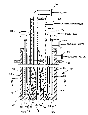
Referring now to Figures :L and 3, there can
be seen a process burner of this invention, generally
designated by the numeral 10. Process burner 10 is
installed with the downstream end passing downwardly
through a port made available in a par-tial oxidation
synthesis gas reactor. Location of process burner 10,
he it at the top or at the side of the reactor, is
dependent upon reactor configuration. Process burner
10 may be installed elther permanently or temporarily
depending upon whether or not it is to be used with
a permanently installed pre-heat burner or is to be
utilized as a replacement for a pre-heat burner, all
in the manner as previously described. Mounting of
process burner 10 is accomplished by the use of annular
flange 48.
Process burner 10 has a centrally disposed
tube 22 which is closed off at its upper end by plate
21 and which as at its lower end a converging frusto-
-conical wall 26. At the apex of frusto-conical wall
26 is opening 35 which is in fluid communication with
acceleration zone 33. Acceleration zone 33, at its
lower end, terminates into opening 30. For the embodi-
ment shown in the drawings, acceleration zone 33 is a
hollow right cylindrically shaped zone.
Passing through and in gas-tight relation-
ship with an aperture in plate 21 is carbonaceous slurry
feed line 14. Carbonaceous slurry feed line 14, at its
lowermost end, is connected to a port in an annular pla-te
17 which closes off the upper end of a distributor 16.
Distributor 16 has a converging frusto-conical lower
wall 19. ~t the apex of frusto-conical wall 19 is
32,475-F -18-
--19--
a downwardly depending tube 28 which defines an annular
slurry conduit 25. The inside diameter of tube 28 is
substantially less than the inside diameter, at its
greatest extent, of dis-tributor 16. It has been found
that by utilizing distributor 16 the flow of carbona-
ceous slurry from the opening found at the bottom of
condùit 25 will be substantially uniform throughout its
annular extent. Determination of the inside diame-ter
of the distributor 16 and the inside diameter of tube
28 is made so that the pressure drop that the carbona-
ceous slurry experiences as it passes through annular
conduit 25, defined by the inside wall of tube 28 and
the outside wall of tube 23, is much greater than the
difference between the highest and lowest pressures
present in the slurry measured across any annular
horizontal cross-sectional plane inside of distributor
16. If this pressure relationship is not maintained,
it has been found that uneven annular flow will occur
from annular conduit 25 resulting in the loss of dis-
persion efficiency when the carbonaceous slurry contactsthe frusto-conical oxygen-containing gas streams as
hereinafter described.
The difference in the inside and outside
diameters of annular conduit 25 is at least partially
dependent upon the fineness of the carbonaceous material
found in the slurry. The diameter differences of
annular conduit 25 should be sufficiently large to pre-
vent plu~ging with the particular size of the carbona-
ceous material found in the slurry utilized. The
difference in inside and outside diameters of annular
conduit 25 will, in many applications, be within the
range of from about 0.1 to about l.0 inches (0.2 to 2.5
cm).
32,475-F -19-
-20-
Coaxial with both the longitudinal axis of
distributor 16 and downwardly depending tube 28 is
tube 23 which has, throughout its extent, a sub-
stantially uniform diameter. The tube 23 provides a
conduit 27 for the passage of an oxygen-containing gas
and is open at both its upstream and downstream ends
with the downstream opening being substantially coplanar
wi-th the opening of the downstream end of tube 28.
The oxygen-containing gas is fed to process
burner 10 through feed line 24. A portion of the
oxygen-containing gas will pass into the open end of
tube 23 and through conduit 27. The remainder of the
oxygen-containing gas flows through annular conduit
31 defined by the inside wall of tube 22 and the out-
side wall of tube 28. The gas passing through conduit31 will be accelerated as it is forced through the
frusto-conical conduit defined by frusto-conical sur-
face 26 and frusto-conical surface 20. The distance
between frusto-conical surfaces 20 and 26 can be such
to provide the oxygen-containing gas velocity required
to effectively disperse the carbonaecous slurry flowing
out of carbonaceous slurry conduit 25. For example,
it has been found that when the oxygen-containing gas
passes through condui-t 27 at a calculated velocity of
about 200 ft/sec and the carbonaceous slurry passes
through annular conduit 25 at a velocity of about
8 ft/sec and has an inside, outside diameter difference
of abou-t 0.3 inches (7.6 cm), the oxygen-containing
gas should pass through the frusto-conical condui-t
at a calculated velocity of about 200 ft/sec. Generally
speaking, for the flows of just and hereinafter
32,475-F -20-
s
-21-
discussed, the distance between the two frusto-conical
surfaces is within the range of from about 0.05 to
about 0.94 inches (0.13 to 2.4 cm). With these flows
and relative velocities, it has also been ound that
the heigh and diameter of acceleration zone 33 should
be 7 inches (17 cm) and about 1.4 inches (3.6 cm),
respectively.
Frusto-conical surface 26 converges to the
extended longitudinal axis of tube 28 ~long an angle
within the range of from about 15 to about 75. If
the angle is too shallow, say 10, then the oxygen-
-containing gas expends much of its energy impacting
the surface. However, if the angle is too deep, then
the shear achieved is minimized.
Concen~rically located with respect to tube
22 is tubular wa-ter jacket 32. Water jacket 32 is closed
off at its uppermost end by annular plate 58. A-t the
lowermost end of water jacket 32 is annular plate 42
which extends inwardly but which provides an annular
water passageway 43. Located within the annular
space 39 found between the outside wall of tube 22
and the inside wall of water jacket 32 are three fuel
gas conduits 36, 40 and 41. The fuel gas conduits
36, 40, and 41 are provided by tubes 36a and 40a and
41a, respectively. Tubes 36a, 40a and 41a pass through
apertures in flange 42 as seen in Figure 1. Fuel gas
is fed through tubes 40a and 36a by way of feed lines
52 and 50 respectively. The feed line for tube 41a
is not shown but is the same type utilized for the
other tubes.
32,475-F -21-
s
.
-22-
As can be seen in Figure 1, fuel gas con-
duits 40 and 36 (and likewise for fuel gas conduit 41),
are angled towards the extended longitudinal axis of
tube 28. The conduits are also equiangularly and
S equidistantly radially spaced about this same axis.
This angling and spacing is beneficial as it uniformly
directs the fuel gas into the carbonaceous slurry/-
oxygen-containing gas dispersion subsequent to its
flow through opening 30. The choice of angularity
for the fuel gas conduits should be such that the fuel
gas is introduced sufficiently far away from the
burner face but not so far as to impede quick mixing
or dispersion of the fuel gas into the carbonaceous
slurry/oxygen-containing gas stream. Generally speaking,
the angles al and a2 as seen in Figure 1 should be
within the range of from about 30 to about 70.
Concentrically mounted and radially displaced
outwardly from the outside wall of water iacket 32 is
burner shell 44. The radial outward displacement of
burner shell 4g provides for an annular water conduit
45. At the upper end of burner shell 44 is water
discharge line 56. As is seen in Figure 1, water
which enters through water feed line 54 flows to and
through water passagewa~ 43 and thence through annular
water conduit 45 and out water discharge line 56. This
flow of water is utilized to keep process burner lO at
a desired and substantially constant temperature.
Burner shell 44 is closed off at its upper
end in a water-tight manner by annular flange 60.
Burner shell 44 is terminated at its lowermost end
by burner face 46.
32,475-F -22-
-23-
In operation, the process burner 10 is
brought on line subsequent -to the reaction zone com-
pleting its pre-heat phase which bri.ngs the zone
to a temperature within the preferred range of
from about 1500 to about 2500F (810 to 1370C~. The
relative proportions of the feed streams and the optional
temperature moderator tha-t are introduced into the reaction
zone through process burner 10, are carefully regulated
so that a substantial portion of -the carbon in the
carbonaceous slurry and the fuel gas is converted to
the desirable C0 and H2 components of the product
gas and so that the proper reaction zone temperature
is maintained.
The dwell time in the reactor for the
feed streams subseguent to their leaving process
burner 10 will be about 1 to about 10 seconds.
The oxygen-containing gas will be fed to
process burner 10 at a temperature dependent upon its
2 content. For air, the temperature will be from
about ambient to about 1200F (650C), while for
pure 2' the temperature will be in the range of
from about ambient to about 800F (427C). The
oxygen-containing gas will be fed under a pressure
of from about 30 to about 3500 psig (O.3 to 24 MPa).
The carbonaceous slurry will be fed at a temperature
of from about ambient to abou-t the saturation temperature
of the liquid carrier and at a pressure of from about 30
to about 3500 psig (O.3 to 24 MPa). The fuel gas, which
is utilized to maintain the reaction zone at the desired
temperature range, is preferably methane and is fed
at a temperature of from about ambient to about 1200F
32,475-F -23-
-24-
(650C) and under a pressure of from about 30 to about
3500 psig (0.3 -to 24 MPa). Quantitatively, the car-
bonaceous slurry, fuel gas and oxygen-containing gas
will be fed in amounts to provide a weight ratio of
free oxygen to carbon which is within the range of
from about 0.9 to about 2.27.
The carbonaceous slurry is fed via feed line
14 to the interior of distributor 16 at a preferred
flow rate of from about 0.1 to about 5 ft/sec (0.03
to 1.5 m/s). Due to the smaller diameter of carbona-
ceous slurry conduit 25, -the velocity of the carbona-
ceous slurry will increase to be within the range of
-- from about 1 to about 50 ft/sec (0.3 to 15 m/s).
The oxygen containing gas is fed through
feed line 24 and is made into two streams, one stream
passing through gas conduit 27 and the other passing
to form a frusto-conical stream in conduit 29. The
oxygen-containing gas streams can have different
velocities, for example, the velocity through gas
20 conduit 27 ca~:be 200 ft/sec (8 to 60 m/s~ and the
velocity through the frusto-conical conduit 29 can
be 300 ft/sec (90 m/s). As mentioned previously,
the annular carbonaceous stream exits carbona-
ceous slurry conduit 25 and is intersected by a frusto-
-conical stream of oxygen-containing gas just beneath
the lowermost extent of tube 28 and tube 23. The
resultant shearing of the annular carbonaceous slurry
stream by the frusto-conical oxygen-containing gas
stream from conduit 27 results in substantially
uniform dispersion of the carbonaceous slurry within
the oxygen-containing gas.
32,475-F -24-
-25~
The resultant dispersion is then passed -through
acceleration zone 33 which is dimensioned and configured
to accelerate the oxygen-containing gas to a sufficient
velocity to further atomize the carbonaceous slurry to
a volume median droplet size within the range of from
about 100 to about 600 microns.
When burner nozzle 10 is initially placed
into operation the rate of fuel gas feed will be
predominant over the rate of carbonaceous slurry
feed. ~s the carbonaceous slurry feed is increased,
however, the rate of fuel gas feed is decreased. This
contemporaneous slow conversion from fuel gas feed
to carbonaceous slurry feed will continue until fuel
gas feed is completely stopped. Should a reaction
zone upset occur and the carbonaceous slurry feed
have to be reduced, then the fuel gas feed will be
brought back on line in an amount sufficient to
keep the reaction zone within the desired temper-
ature range.
Referring now to Figures 2 and 4, there can
be seen another embodiment of this invention which is
senerally designated by the numeral 110. Process
burner 110 has a central tube 112 which is closed
off at its upper end ~y plate 114. Also located
at the upper end of tube 112 is carbonaceous slurry
feed line 122. Tube 112 defines within its interior
carbonaceous slurry conduit 113 which has at is lower-
most portion an area of reduced diameter 116. ~y
reducing the diameter of the lowermost portion, the
carbonaceous slurry feed is accelerated to a veloci-ty
of from about 1 to about 50 ft/sec (0.3 to 15 m/s).
32,475-F -25-
-26-
By having the larger diameter for tube 112 above the
area of reduced diameter less plugging of tube 112
is experienced.
Tube 124 is concentric to and has an inside
diameter greater than the outside diame-ter of tube 112.
Tube 124 is closed off at its upper end by annular
plate 120 which has an aperture therein for -the mounting
of tube 112 as is seen in F:Lgure 2. Oxygen-containing
gas feed line 144 is provided near the upp~r extent
of tube 124. Tube 124, at its lower end, has a con-
verging frusto-conical surface 126. This surface
extends to a point beneath the inside surface which
defines reduced diameter 116 as is shown in Figure 2
Frusto-conical surface 126, in conjunction with
frusto-conical surface 118, provides a frusto-conical
conduit 127 for the passage of the oxygen-containing
gas. The distance between frusto-conical surfaces
118 and 126 is determined by the desired velocity
for the oxygen-containing gas as it passes through the
frusto-conical conduit 127. Generally speaking, for
flows hereinafter discussed, the distance between
the two frusto-conical surfaces is within the range
of from about 0.05 to about 0.95 inches (0.13 to 2.~ cm).
The desired velocity of the oxygen-containing gas as it
passes through frusto-conical conduit 127 will affect
the shearing of the carbonaceous slurry as it exits
conduit 113. This shearing results in a substantially
uniform dispersion of the carbonaceous slurry in the
oxygen-containing gas.
The frusto-conical surface converges to the
extended longitudinal axis of tube 112 along an angle
32,475-F -26-
-27-
within the range of from about 15 to about 75.
If the angle is too shallow, say 10, then the oxygen-
-containing gas expends much of its energy impacting
the surface. However, if the angle is too deep, -then
the shear achieved ls minimized.
Located at the ape;~ of frusto-conical
surface 126 is acceleration zone 130. For the embodi-
ment shown in Figures 2 and 4, this acceleration zone
is a hollow right cylinder hlaving an opening at its
upper end 131 and an opening 133 at its lower end.
The dimensions of acceleration 20ne 130 can be the same
as those for acceleration zone 33 used for the embodi-
ment of Figures 1 and 3, assuming comparahle stream
flows. It may be beneficial to provide the acceleration
zone with a wear resistant lining such as one made of
tungsten carbide.
Concentrically mounted and radiall~ displaced
outward from the outside wall of tube 124 is water
jacket 146. Water jacket 146 is closed off at its
upper end by annular plate 148 which has an aperture
therein for the passing and mounting of tube 124 as
can be seen in Figure 2. Plate 14~ also has three
further apertures which are used for the passing
and m~unting of fuel gas feed lines 136 and 138
and the not shown feed line which is associated
with fuel gas tube 143. Water jacket 146 provides
an annular space 145 defined by its inside wall
and the outside wall of tube 124. Within annular
space 145, there are located three fuel gas tubes
142, 143 and 152. These tubes define respectively
fuel gas conduits 142a, 143a and 152a. As can be
seen Figure 2 and 4, fuel gas tubes 142, 143 and 152
32,475-F -27-
s ~ ~
-28-
are equiangularly and equiradially spaced from and
angled downwardly towards the extended longitudinal
axis of tube 112. The purpose of such angling and
spacing for the emhodiments shown in Figures 2 and
4 is the same for -the angling of the fuel gas tubes
described hereinabove for the embodiments shown
in Figures 1 and 3.
Not only does annular space 145 contain
the fuel gas tubes, but also it is utilized to provide
a conduit for the passage of cooling water which
is fed in through cooling water feed line 150 which
is located at the upper end of water jacket 146. Water
jacket 146 has at its lower end an annular plate which
provides for water passageway 147 as shown in Figure 2.
Also note that the fuel gas tubes pass through apertures
in annular flange 140 for mounting purposes.
Also provided by process burner 110 is
concentric outer burner shell 154 having a bottom face
1580 Outer burner shell 154 is radially displaced
outwardly so that its inside wall and the outside
wall of tube 146 provide for cooling water conduit
151. Water conduit 151 is in liquid communication
with annular space 145 by way of water passageway
147. Thus, water entering water feed line 150
passes through annular space 145, to passageway 147
and thence upward in conduit 151 so that it can be
discharged through discharge line 160. Water con
duit 151 is closed off at its top by annular flan~e
156.
32,475-F -28-
.11.~3~
-29-
Process burner 110 is mounted to the gas
generator by way of flange 162 so that process burner
110 discharges directly into the reaction zone. The
mounting of process burner 110 can be either in a
temporary or permanent fashion depending upon whether
or not it is to be utilized as a replacement for the
pre-heat burner or is to be utilized in conjunction
with a permanently mounted pre-heat burner. The
temporary mounting is used when the pre-heat burner
is to be replaced by process burner 110 after the
reaction zone has been brought to the desired tem-
perature range. Permanent mounting is used when the
pre-heat burner is permanently affixed to the vessel.
In operation, process burner 110 is brought
on line subsequent to the reaction zone completing its
preheat phase to bring it to a temperature of from about
1500 to about 2500F (810 to 1370C). The dwell time
in the reactor for the feed streams, subsequent to
their leaving the process burner is from about 1 to
about 10 seconds. The oxygen-containing gas fed to
proces burner 110 is at a temperature within the
range of from about ambient to about 1200F (650C)
while the carbonaceous slurry will be fed at a tem-
perature of from about ambient to saturation temperature
of the carrier liquid. The fuel gas is supplied to
process burner 110 at a temperature of from about
ambient to about 1200F (650C). Pressure-wise, the
oxygen-containing gas is fed to the burner at a pres-
sure of from about 30 to about 3500 psig, (0.3 to 24
MPa) while the carbonaceous slurry is fed under a
pressure of from about 30 to about 3500 psig (0.3 to
24 MPA). The pressure under which the fuel gas is fed
32,475-F -29-
s
-30-
is advantageously from about 30 to about 3500 psig
(0.3 to 24 MPa). Carbonaceous slurry, fuel gas and
oxygen-containing gas are supplied to the burner
in amounts sufficient to provide a weight ratio of
free oxygen to carbon within the range of from about
0.9 to about 2.27.
When burner nozzle 110 is initially placed
into operation, the rate of fuel gas feed will be pre-
dominant over the rate of carbonaceous slurry feed.
The carbonaceous slurry feed increases as the fuel gas
feed is decreased until there is no fuel gas feed and
the carbonaceous slurry feed is at its maximum rate.
Should there be reason to interrupt the carbonaceous
feed slurry totally or in part the fuel gas feed can
be brought on line to aid in the maintenance of the
reaction zone temperature.
The carbonaceous slurry is fed through feed
line 112 at the rate of from about 0.1 to about 5 ft/sec
(0.03 to 1.5 m/s). As the carbonaceous slurry moves
through conduit 113, it encountes the reduced diameter
portion 116 of tube 112. The velocity of the carbona-
ceous slurry is thereby increased to be within the
range of from about 1 to about 50 ft/sec (0.3 to
15 m/s). Carbonaceous slurry exits tube 112 and
encounters a frusto-conical stream of oxygen-con-
taining gas which is provided through frusto-conical
conduit 127. This frusto-conical stream has a
velocity ~lithin the range of from about 75 ft/sec
(23 m/s) to about sonic. The resultant shearlng
of the carbonaceous slurry stream results in its
being substantially uniformly dispersed within the
32,~75-F -30-
-31-
oxygen-containing gas. The dispersed mix then
passes through acceleration zone 130 which has a
cross-sectional area of conduit 113 and frusto-
-conical conduit 127. As is the case for the
acceleration zone previously described for the
embodiment of Figures 1 and 3, acceleration zone
130 has a lower pressure at its lower opening 133
than it does at its upper opening 131. This dif-
ference in pressure accelerates the oxygen-containing
gas so that it causes atomization of the dispersed
carbonaceous slurry as the dispersion mix passes
through the acceleration zone. Atomization within
the range of from about 100 to about 600 microns
is achieved.
The fuel gas, when fed to the process burner,
is fed through fuel gas feed lines 136, 138 and a like
line which is not shown.
32,475-F ~31-