Note : Les descriptions sont présentées dans la langue officielle dans laquelle elles ont été soumises.
;~
The ir)~Rntiorl rela-t.es to ~`our-wheel~d automotive
vehicles in whicl~ the f~r whe.3ls have ~ quadrilateral
configura-tiorl~
hour-wlleele~ automotive ~el~icles are known in which
the wheels f~rm a s~are .lngled ~uadrilateral at the ends
of the two front a~ld rear ~heel a~les~ They are usually
provided with fronl; steel~in~ wheels.
This solution, in which th~ four whee:l~; have a square
quadrilateral con~`iguratioll, has probably reached its
optimisation as far as perorlnance i5 concerned and no
further significant i~nprovemen~s or better roadabilitr can
prvba~ly be achieved.
1'~le inventiorl has the aim to c~btain improvement by
positior~ g the ~our wtteels in a rhvmboidal corlfi~ulation.
This onf~uratiorl enormously increases t,he roadability of
the.se vehic:l.es especialLy in curves. ~hereas in a
quadrilateral configuratiorl, the vehicle is only acting ~n
the two external wheel~, in a rhomboidaL wheel
configuration, road resistance is supported at least by
three wheel 5 .
An automotive ~ehicle ha~ing a r~lvmboidal wheel
configuration was already pr~posed as far bsck as 191~, but
resu:L-t~ wer~ unsatisfactory because o-f numerous ~rawhacks.
First of all, the centre ~ gravity of the vetlicle was not
centralized 50 th~t di~erential forces were act:ing on the
wheels. A secorld disadvarltage was that only t~le front wheel
was. SteeriTlg, wh.i.ch easi]y ]ed to skidding in cur~es and
also involved heavy wear vn the tixes.
1n addition, there was the fact that ~nly the central
wheeLs were dri~irtg, .si~lce ~t th~t -time intsgral four whee~
3 2!:t3~15
dri~re for private ~n~ raee cars was still ullknowll. A
similar car was introduced in 1960~ but with i~,S wheels in
Y-con~`iguration.
'l'his car als~ was no ~`urtller improvement; since i-t had
almost the same cl.isad~arlta~e as its ancestor
Substantially the au-tomotive vehicle according to
this invention seek.s to eliminat~ t~e above mentioned
dr~w~ cks wh.ile o~':t`eri.ng several struct~lral and functiorlal
advanta~es, tLlU~ maki.ng l,he adoption of the rhomboidal
wheel confi~uration highly attractive.
With a ~iew to achievin~ the foregoirl~ objectives the
inventiorl comprises an au-tomot,ive vehicle having one single
chassis or bearing frame with the centre o-f ~ravity of the
car substantially locat~d in the centre o~ the frame,
self-aligning trapezoi~lal suspensiorl of the central wheels,
L-shape~l floating arm suspensions on the front and rear
wheels, all four wheel.s bein~ d~iving wheels, front and
xear wheels steering vn articulated joints mounted on
L-shaped ~`loating suspensiorls, and a steerin~ gear-box
consisting of a rack and Uinion gear, with external
conrlection to the ~`ront ancl back wheels i.e. in opposite
position with respect to connection to the dr.ive sha~t.
The various 1`eatures of novelty which characterize
the invention are pointed out with more particularity in
the claims anrlexed to and formirlg a part of this
disclosure. For a ~etter understandin~ of the invsntion,
its operating advanta~es and specii'ic ob,jects attained by
i-ts use~ reference shou:ld ~e had to the accompanyin~
drawings arld descrlpti~e matter in which there are
illustrated and described pre~erred embodiments of the
~2~3695
.in~ent iC'I'~ .
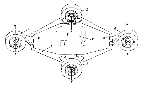
r N T~h_~R~WIN~`:S
~ ure 1 5hows a perspective ~iew o~ the vehicle
:trame or ~hassis wil;h t~le ~Jhe~.ls mounted i~l rhomboidal
configuration;
Figures 2 and 3 respecti.~ely show front an~l rear
views of the assembly illustrated in Fi~.1;
E'.igures 4 and 5 illustr~te the steering gear actirlg
contemporan~ousl.y on the front and rear wheels;
E'igure 6 is a perspective ~iew of the steerin~ gear
housing;
Fig. 7 is a perspecti~e ~iew o~ the h-shaped floating
arm of the castor wheels, and,
E'ig. 8 is a side view of the ~astening and steerin~
mechànisms for the front wheel.
WitE~ re~erence to these illustrations, the vehicle
fra~e or chassis 1 ~las a rhomboid configuration, on which
central wheels 2 and 3 and front and rear steerin~ wheels 4
and 5 are mounted. The central whe~ls 2 and 3 are supported
alon~ a centre axis 6 ~y self-ali~ning trapezoidal
suspensions '7. The front and re~r wheels 4 and 5 are
sllpported alon~ a hori~ontal axis by L-shaped ~loatin~ arm
type suspensions 8 fitted with a vertical pin ~ providing
for steering of the wheels 4 and 5. The engine 10 is
located itl the central part o~ the chassis so that t;he
center of gravity is located as centrally as possible with
respec-t to the rhombus ~ormed by the chassis and by the
wheels 2~ 3, 4 and 5.
E'i.gures 4 and ~ show ~hat t,he ~ront and rear wheels 4
and 5 are castori.tlg in opposite directiotls. A steering
.,~ .
12~3695
whe~l ll, operates throu~h steering column 1~ and double
joint 1~ on drive case 14~ ~rive case 14 controls wheels 4
and 5 -through rods 1~ and 16 connected br ball and socket
joints 17.
Ball and socket joints 1'7 are linke~ up to the out~r
end of a r~tating rod 18, fastened on the outside of the
wheel on the opposite side with respect to the steering pin
9.
Figures ~ ancl 5 respectively show le-~ and ri.~ht
st~ering.
~ rive case 14 houses a pinion 19 and two oppos~d
rack.s 20. and 21, respecti.vely connected to steering
ontrol rods 15 and 16 as ~hown in E'ig. 6. '~'he pinion 19 is
driven ~y the steering wheel 11, through steerirlg colu~n 12
arrd dc>uble joint 13.
l'h.is soluti.on permits at the same time steerin~ of
both wheels in opposite directions around pins ~. l'he
floating arm 8 of wheels 4 and 5 is sho~n in greater detai~
in Fig. 7. Floating arm 8 is L-shaped and has at on~ end
articulation bearin~s ~2 on a hori20ntal axis hin~ed on
chassi.s 1. On its otllel elld holes 23 Ot) a v~rtical axis
accommo(late the steering pin 9.
Arly and all movements of floating arm 8 due to
unevensss of the road are compensated by a large-sized
spring 24 and dampex 25, located between the arm 8 and a
fixed point 26 o-f the bearin~ ~rame or chassis.
The rnechanical transmissioll systems 27, 28, 29 are
mounted on bearings 30 and transmit the drive ~rom ~he
engine to the wheels 4 and 5. Centr~ wheels ~ and 3 are
al50 dri.ven by drive transmissiorl means ~not shown) of any
12~3695
~suita~Le desi~n~
~ 'ig ~1 sh~ws t}le arrang~men-t oP t~e steering wheels
4. and ~ on their supporting floating arms 8~ A support ~1
is .Linked l~p to float.ing arm 8 Ly means of two knuckl~
joints 9a, usually secured by two pins. Support 31 supports
the driving shaft 34~ complete with bearings 32 and
register 33 t and is actuated through universal joint 35, by
-the driving shaft 29. A br~ke disk 36 and a ~lan~e 3'~
fastened with holts 3~ on to the whee~ rlm 4 are mounted on
the drive shaft 3~ A second flange 39 is secured with the
sam~ bolts .38 on the outer surface of the rim of wheeL 4.
This second flan~e .3~ carries a steering rod 18, one end of
which i5 fitted usually with a double-ball and socket jolnt
17, complete with bearing ~, k~pt in pl&ce by a bolt 41.
Bearirlg 40 permit.s connectiorl of the re~olving rod 18 to
the non-rotating steering rods t5 and 16.
The syste,m described above can also be suitably
applied to toys and in particular to car models, now used
to reproduce on a small scale the cons-truction particulars
and functions of series built automotive vehicles and race
cars.
Having des~ri~ed what is believed to ~e the ~est mode
b~ which the invention may be performed, it will be seen
that the invention may be particularly defined as follows:
An automotive vehicle comprising a frame having a
longitudinal. axis extending along the direction o~ ~'orward
advancement of the vehiGle, and a trarlsverse axis extending
tran.sve:rsely of the longi.tudina.1 axis, said frame bei.ng
gerlerally symmetrical about said axes, means for mounting a
~ront wheel and a rear wheel orl the frame in alignment
36~S
alo~lg the lot~it,~lditlal axis, including i~dividual front ~nd
r~ar wheel suspensions, mean~ for mounting a pair of side
wheels mounted on the frame in alignmerlt alo~lg the
transverse axis including individual side wheel
suspensions, drive mearls mounted cerltrally of the fram~ for
~enerati.ng moti~e power, transmission means operatively
connected betwcen the drive means and the wheels, t`or
rotatably driving each of -the wheels~ said transmission
means including trarlsmissiorl co-nponerlts supporta~l~ mounted
on the front and rear wheel suspensions, and steering means
moun~ed on the frame and operativels~ connected to both the
front and rear wheels, for simultaneously affirmatively
steering both the ~'rorlt and tl~e rear wheels in opposite
circumferential directions about respective vertical
stecrirlg axes eY.tending ~enerally perperldicular to the
longitudinal and t,ransverse axes of the frame.
The foregoin~ i.s a description of a preferred
embodiment of the invention which is given here by way of
example only. 'rhe invention is not to be taken as limited
to a.ny of the specific ~eatures as describecl, but
comprehends all such variatiorls thereof as come within the
scope of the ap~ended claims.