Note : Les descriptions sont présentées dans la langue officielle dans laquelle elles ont été soumises.
~ 43~4
GAS-FIRED FURNACE CONTROL APPARATUS
AND METHOD FOR MAINTAINING AN
OPTIMUM FUEL AIR RATIO
Background of the Invention
This invention pertains to furnaces, and more particularly to
a control apparatus and method for a ga~-fired furnace which
maintains an optimum fuel air combustion ratio therefor.
Present technology for direct vent gas-fired furnace design
generally requires the furnace to be operated at less than
the optimum fuel air combustion ratio due to variations in
certain parameters, such as vent pipe length, barometric
pressure, and BTU content of the natural gas. As a result,
the present technique is to design the furnace to operate for
anticipated maximum vent pipe length, anticipated highest
altitude at which the furnace might be installed, and
anticipated maximum BTU content of the gas. Therefore, when
the furnace is installed at other than these three
anticipated conditions, the furnace will operate with excess
combustion air, and as a result thereof, will operate at
reduced efficiency.
Summary of the Invention
The present invention provides a control apparatus and method
for automatically regulating the manifold gas pressure to
provide an optimum gas flow in response to varying
parameters. This is accomplished by measuring the pressure
drop across the heat exchangers by means of a differential
pressure transducer and generating a signal indicative of the
changing pressure drop. Since the pressure drop varies with
vent pipe length, barometric pressure, gas line pressure,
temperatures, and the like, the pressure drop signal is used
as an input to a microprocessor control that has its control
logic preprogrammed to automatically regulate the manifold
gas pressure to a desired optimum level as a function of heat
12943'~4
exchanger pressure drop. Consequently, a furnace operated in
accordance with the present invention will operate generally
at a higher level efficiency than previously possible.
It is an object of the present invention to provide an
improved control apparatus for a gas fired furnace that
compensates for variation in certain operating parameters.
Another object of the present invention is to provide a
method for maintaining opti~um fuel air combustion ratio in a
gas-fired furnace.
Yet another obiect of the present invention is to provide a
control apparatus for a gas-fîred furnace that utilizes the
pressure drop across the heat exchangers to maintain an
optimum fuel air combustion ratio.
A further object of the present invention is to provide a
method that uses the pressure drop across the heat exchangers
for maintaining an optimum fuel air combustion ratio.
Further objects of the present invention will appear as the
description proceeds.
In one form of the invention, there is provided in a
gas-fired furnace a fuel regulator connected to a combustion
chamber for supplying a regulated flow of fuel thereto in
response to a received control signal, a pressure
differential measuring device for measuring the pressure drop
across heat e~changers in the furnace and for generating a
pressure differential signal in response thereto, and a
control device for receiving the pressure differential signal
and for generating in response thereto a control signal to
the fuel regulator, whereby the flow of fuel to the
combustion chamber is regulated as a function of the pressure
lZ~3'~4 i!
drop across the heat exchangers to maintain an optimum fuel
air combustion ratio.
In other form of the invention, there is provided a method
for maintaining,an optimum fuel air combustion ratio in a
gas-fired furnace comprising the steps of supplying a flow of
fuel from a fuel source to a combustion apparatus for
combusting with the combustion air, measuring the pressure
drop across heat eY.changers in the furnace caused by the flow
of combusted fuel air mixture, and regulating the supply of
fuel flow to the combustion apparatus as a function of the
measured pressure drop across the heat e~,;changers to maintain
an optimum fuel air combustion ratio.
Brief Description of the Drawings
The above-mentioned and other features and objects of this
invention, and the manner of attaining them, will become more
apparent and the invention itself will be better understood
by reference to the following description of an embodiment of
the invention taken in conjunction with the accompanying
drawings, wherein:
Figure 1 is a partially broken-away side elevational view of
a furnace incorporating the principles of the present
invention;
Figure 2 includes a sectional view of a gas supply valve in
conjunction with a schematic of a furnace control system
incorporating the principles of the present invention;
Figure 3 is a plot of a curve indicating the relationship
between heat exchanger pressure differential and optimum
manifold gas pressure; and
Figure 4 is a block diagram of a portion of the furnace
control system.
4 lZ9~3~
Detailed Description
Referring to Figure 1, ~here is illustrated a gas-fired
furnace which may be operated according to the principles of
the present invention. The following description is made
with reference to condensing furnace 10, but it should be
understood that the present invention contemplates
incorporation with a noncondensing-type furnace. Referring
now to Figure 1, condensing furnace 10 includes in major part
steel cabinet 12 housing therein burner asse~bly 14, gas
regulator 16, heat exchanger assembly 18, inducer housing 20
supporting inducer motor 22 and inducer wheel 24, and
circulating air blower 26. Gas regulator 16 includes pilot
circuitry for controlling and proving the pilot flame. This
pilot circuitry or control can be a BDP model 740A pilot
obtainable from BDP Company, Indianapolis, Indiana.
Burner assembly 14 includes at least one inshot burner 28 for
at least one primary heat exchanger 30. Burner 28 receives a
flow of combustible gas from gas regulator 16 and injects the
fuel gas into primary heat exchanger 30. A part of the
injection process includes drawing air into heat exchanger
assembly 18 so that the fuel gas and air mixture may be
combusted therein. A flow of combustion air is delivered
through combustion air inlet 32 to be mixed with the gas
delivered to burner assembly 14.
Primary heat exchanger 30 includes an outlet 34 opening into
chanber 36. Connected to chamber 36 and in fluid
communication therewith is at least one condensing heat
exchanger 38 having an inlet 40 and an outlet 42. Outlet 42
opens into chamber 44 for venting exhaust flue gases and
condensate.
Inducer housing 20 is connected to chamber 44 and has mounted
therewith inducer motor 22 with inducer wheel 24 for drawing
the combusted fuel air mixture from burner assembly 14
12~3 ~4
through heat exchanger assembly 18. Air blower 26 delivers
air to be heated upwardly through air passage 52 and over
heat exchanger assembly 18, and the cool air passing over
condensing heat exchanger 38 lowers the heat exchanger wall
temperature below the dew point of the combusted fuel air
~ixture causing a portion of the water vapor in the combusted
fuel air mixture to condense, thereby recovering a portion of
the sensible and latent heat energy. The condensate formed
within heat exchanger 38 flows through chamber 44 into drain
tube 46 to condensate trap assembly 48. As air blower 26
continues to urge a flow of air to be heated upwardly through
heat exchanger assembly 18, heat energy is transferred from
the combusted fuel air mixture flowing through heat
exchangers 30 and 38 to heat the air circulated by blower 26.
Finally, the combusted fuel air mixture that flows through
heat exchangers 30 and 38 exits through outlet 42 and is then
delivered by inducer motor 22 through exhaust gas outlet 50
and thence to a vent pipe (not shown).
Cabinet 12 also houses microprocessor control assembly 54,
LED display 56, pressure tap 58 at primary heat exchanger
inlet 60, pressure tap 62 at condensing heat exchanger outlet
42 and limit switch 64 disposed in air passage 52; the
purposes of which will be explained in greater detail below.
If condensing furnace 10 is replaced with a
noncondensing-type furnace, then naturally pressure tap 62
would be disposed st primary heat exchanger outlet 34, since
there would be no condensing heat exchanger 38.
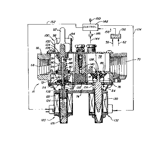
Referring now to Figure 2, gas regulator 16 generally
comprises valve body 66 having an inlet 68 and outlet 70.
~etween inlet 68 and outlet 70 are a series of chambers, in
particular, inlet chamber 72, intermediate chamber 74,
regulator chamber 76, and main chamber 78. These chambers
are in fluid communication, directly or indirectly, with
val~e body inlet 68 and outlet 70; inlet 68 communicates with
6 lZ~3~
inlet chamber 72 through inlet cha~ber seat 80, inlet chamber
72 communicates with intermediate chamber 74 through
intermediate chamber seat 82, intermediate chamber 74
communicates with regulator chamber 76 through regulator seat
84, regulator chamber 76 communicates with main chamber 78
through main seat 86, and main chamber 78 communicates with
outlet 70. The use of the term "seat" is equivalent to terms
such as "opening", "hole", and the like.
Each of the above mentioned seats are closed and opened by
particular members. IIIlet chamber seat 80 is closed and
opened by manually-operated valve head 88. Valve head 88 is
connected to plunger 90, which is slidably received through
valve body 66 in a fluid-tight manner. The externally remote
end of plunger 90 is suitably connected to manual on-off
lever 92, which is surrounded by indicator bracket 94.
Bracket 94 is connected to valve body 66 in any suitable
manner. Spring 96 is disposed within inlet 68 and between
valve head 88 and the valve top cover plate 91 50 as to bias
valve head 88 into seating engagement with inlet chamber seat
80, thereby to prevent fluid communication between inlet 68
and inlet chamber 7 O-ring 89 insures a fluid tight fit
between valve head 88 and seat 80. To open or move valve
head 88 to an open position to allow fluid communication
between inlet 68 and inlet chamber 72, manual on-off lever 92
is rotated in a counter-clockwise direction, as viewed in
Figure 2. Manual on-off lever 92 includes an enlarged end
portion 98 that has a camming surface 100. Camming surface
100 is defined by two relatively flat surfaces 102 and 104
that are generally perpendicularly disposed to each other and
joined by a generally curved surface 106. As seen in Figure
2, manual lever 92 is in the closed position so that spring
96 is biasing valve head 88 into seating engagement with
inlet chamber seat 80 in a fluid-tight manner. ~s manual
lever 92 is rotated counter-clockwise, the action of camming
surface 100 and enla~ged end portion 98 causes plunger 90 to
7 :1Z~3.~4
be pulled upwardly a~ainst the force of spring 96 to separate
val~e head 88 from inlet chamber seat 80, thereby permitting
fluid communication between inlet 68 and inlet chamber 72.
Manual lever 92 is held in the open position by the engaging
force or friction existing between flat surface 102 and the
flat exterior surface portion of valve body 66. Naturally,
to close inlet chamber seat 80, manual lever 92 i5 rotated
clockwise to permit spring 96 to extend plunger 90
downwardly, thereby permitting valve head 88 to engage inlet
chamber seat 80.
Intermediate chamber seat 82 is opened and closed by valve
seat disc 108, which is disposed in inlet chamber 72. ~alve
seat disc 108 has a secondary plunger 110 connected thereto
in any suitable manner and secondary plunger 110 is slidably
received in bore 112 disposed in valve head 88 and plunger
90. Spring 114 is disposed in inlet chamber 72 between valve
seat disc 108 and oppositely disposed inlet chamber upper
surface 116. Spring 114 biases valve seat disc downwardly to
close intermediate chamber seat 82 in a fluid tight manner.
A rubber portion 109 insures a fluid tight fit between disc
lQ8 and seat 82. Valve seat di8c 108 is connected to
secondary plunger 110 so that valve seat disc 108 moves in a
generally vertical or straight line dlrection generally
perpendicular to the plane of intermediate chamber seat 82,
thereby insuring a fluid tight closure of intermediate
chamber seat 82 when valve seat disc 108 is in the closed
position, as illustrated in Figure 2. Disposed on the
opposite side of valve seat disc 108 and in general axial
alignment with secondary plunger 110 is push rod 118. Push
rod 118 abuts agAinst the undersurface of valve seat disc
108, and upon being moved in an upwardly direction, push rod
118 moves valve seat disc 108 upwardly against spring 114 to
open intermediate chamber seat 82, thereby permitting fluid
communication between inlet chamber 72 and ~ntermediate
chamber 74. Push rod 118 is moved in an up and down
8 1Z~3~4
direction, as viewed in Figure 2, by pick and hold solenoid
120. Solenoid 120 is connected to valve body 66 in any
suitable manner and includes a joining segment 122 extending
slightly inwardly of intermediate chamber 74. Joining
segment 122 provides a fluid tight fit or connection between
solenoid 120 and intermediate chamber 74. Joining segment
122 has an axial passage 124 for slidably receiving push rod
118 therein, with the lower remote end of push rod 118 being
fiY.ed loosely to movable plunger 126 of solenoid 120. When
solenoid 120 is in a de-energized state, plunger 126 and push
rod 118 are located in a lowermost position, a~ illu~trated
in Figure 2, so that spring 114 biases valve seat disc 108 in
fluid tight engagement with intermediate chamber seat 82.
Upon energizing solenoid 120, plunger 126 and push rod 118
move upwardly against valve seat disc 108 and spring 114,
thereby to open intermediate chamber seat 82 to allow fluid
communication between inlet chamber 72 and inter~ediate
chamber 74.
The fluid communication between intermediate chamber 74,
regulator chamber 76, and main chamber 78 are closely related
in that the opening and closing of regulator seat 84 and main
seat 86 are controlled by a ~ingle regulator valve disc 128
disposed in regulator chamber 76. It should be noted that
regulator seat 84 and main seat 86 are generally oppositely
disposed from each other in regulator chamber 76 and are in
generally axial alignment with each other, whereby the axial
or linear movement of regulator valve disc 128 regulates the
fluid communication between intermediate chamber 74,
regulator chamber 76, and main chamber 78. Regulator valve
disc 128 is connected in any suitable manner to re~ulator
plunger 130 of regulator solenoid 132. A sprin~ 134 is
disposed against the underside of regulator valve disc 128
and through regulator seat 84, and biases regulator valve
disc 128 upwardly to close main seat 86 in a fluid tight
fashion. The upper portion 136 of regulator valve disc 128
9 1294344
is made of a rubber material to ensure fluid tight engagement
between valve disc 128 and main seat 86. Regulator ~alve
disc 128 is moved downwardly from its uppermost position
where it clo~es main seat 86 to a lowermost position where it
closes regulator seat 84, thereby opening main seat 86 to
permit fluid communication between regulator chamber 76 and
main chamber 78. Re~ulator valve disc 128 is moved to its
lowermost position upon energizing regulator solenoid 132,
which pulls regulator plunger 130 downwardly until valve disc
128 seats aga~nst regulator seat 84. By controlling the
voltage to regulator solenoid 132, which will be explained in
greater detail below, regulator valve disc 128 is
positionable to an infinite number of positions between its
uppermost position where it closes main seat 86 and its
lowermost position where it closes re~ulator seat 84.
Naturally, any position, other than the uppermost and
lowermost positions, will provide simultaneous fluid
communication bet~een intermediate chamber 74, regulator
chamber 76, and main chamber 78.
Disposed in fluid communication with intermediate chamber 74
are pilot filter 138 and pilot conduit 140 for respectively
filtering the portion of the ~as flowing through ~ilter 138
and delivering it through pilot conduit 140 to the pilot
flame sssembly, which is part of gas regulator and pilot
circuitry 16 (Figure 4).
A pressure-tap port 142 is disposed in regulator chamber 76
for transmitting ~ariations in fluid pressure from chamber 76
through line 144 to pressure transducer 146. Pressure
transducer 146 then generates an analog signal to
microprocessor control 148 indicative of a change in fluid
pressure in regulator chamber 76. Microprocessor control 148
is located in microprocessor control assembly 54 in
condensing furnace 10, and is capable of being preprogr2mmed
to generate a plurality of control signals in response to
~:2~ 3~
received input signals. Microprocessor control 148 is also
connected electrically to thermostat 150 to receive signals
therefrom, to pick and hold solenoid 120 by electric~l lines
152, and to regulator solenoid 132 by electrical lines 154.
Referring to Figure 4, there is illustrated a simplified
block diagram illustrating the interconnection between
microprocessor control 148 and pressure taps 58, 62 through
differential pressure transducer 156. As illustrated in
Figure 2, differential pressure transducer 156 receives
pressure tap inputs from pressure taps 58, 62 and generates
an analog signal indicative of the differential pressure to
microprocessor control 148 via electrical lines 158.
Still referring to Figure 4, it can be seen that
microprocessor control 148 is electrically connected to limit
switch 64 (Figure 1), gas valve 16 through electrical lines
152, 154, and also to air blower motor control 160 of air
blower 26 through electrical lines 162, and inducer motor
control 164 of inducer motor 22 through electrical lines 166.
Air blower motor control 160 and inducer motor control 164
respectively control the rate of fluid flow created by air
blower 26 and inducer wheel 24.
With the manual on-off lever 92 moved in a counter-clockwise
position to open inlet chamber seat 80, and upon closing of
contacts in thermostat 150 indicating a need for heat,
microprocessor control 148 is programmed to send a signal via
electrical lines 166 (Figure 4) to inducer motor control 16~
to start inducer motor 22 to rotate inducer wheel 24~ thereby
causing a flow of combustion air through combustion air inlet
32, burner assembly 14, heat exchanger assembly 18, inducer
housing 20, and out eY~haust gas outlet 50. After a
predetermined period of time, for example, ten seconds, to
ensure purging of the furnace, microprocessor control 148
generates a signal through electrical lines 152 ~o pick and
11 ~2943-~
hold solenoid 120, thereby energizing it to move plunger 126
upwardly so that push rod 118 separates valve seat disc 108
from intermediate chamber seat 82 to permit gas flow from
inlet chamber 72 to intermediate chamber 74. The gas flows
then to and through pilot filter 138 and pilot conduit 140 to
initiate the pilot flame, and flows also into regulator
chamber 76 where the pressure is sensed at pressure-tap port
142. Ignition of the pilot flame is p~oved by the pilot
circuitry in the pilot control of gas regulator 16 and a
signal is generated to microprocessor control 148 through
electrical lines 152, 154 (Figure 4) to indicate the flame is
proved.
During this period of time, microprocessor control 148
(Figure .~) is monitoring the pressure drop across heat
exchanger assembly 18, which is provided by pressure taps 58,
62 transmitting pressure readings to differential pressure
transducer 156. Differential presSUre transducer 156 sends a
pressure differential signal through electrical lines 158 to
microprocessor control 148 indicative of the presSure drop
reading. Pressure-tap port 142 is also transmitting
increasing gas pressure in regulator chamber 76 through line
144 to pressure transducer 146, which generates an analog
signal indicative of the increasing gas pressure to
microprocessor control 148. After microprocessor control 148
determines a sufficient pressure drop exists across heat
exchanger assembly 18, that the g&S pressure in regulator
chamber 76 is at or above a predetermined pressure, and the
pilot flame has been proved, microprocessor control 148 is
programmed to generate a voltage signal through electrical
lines 154 to regulator solenoid 132. During this period of
time, regulator valve disc 128 is closing off main seat 86 of
main chamber 78 to prevent gas flow therethrough.
Because of the relatively high pressure existing in regulator
chamber 76, the signal generated from microprocessor control
12 ~Z~ 4 3~4
148 to regulator solenoid 132 is of a relatively high voltage
to cause solenoid 132 to pull regulator plunger 130 to its
lowermost position, whereby regulator valve disc 128 opens
main seat 86 and closes regulator seat 84. This prevents
fluid communication between regulator chamber 76 and
intermediate chamber 74, but does permit fluid communication
between regulator chamber 76 and main chamber 78. Thus, the
increased gas pressure in regulator chamber 76 bleeds off
through main seat 86, main cha~ber 78, and through outlet 70.
This decreasing gas pressure in reglllator chamber 76 is
continually monitored by microprocessor control 148 through
port 142 and upon rPaching a predetermined low pressure,
microprocessor control 148 generates a relati~ely low voltage
signal to re~ulator solenoid 132 to open regulator seat 84 by
moving regulator plunger 130 to an intermediate position
between its uppermost position where it closes off main seat
86 and its lowermost position where it close6 off regulator
seat 84. Microprocessor control 148 is preprogrammed to
position ~egulator valve disc 128 in regulator chamber 76 to
provide a desired gas flow rate and pressure in main chamber
78.
Thereafter, gas flow is provided by gas regulator 16 to
burner assembly 14 and the fuel air mixture is combusted by
inshot burner 28. The combusted fuel air mixture is then
drawn through heat exchanger assembly 18 and out exhaust gas
outlet 50 by the rotation of inducer wheel 24 by motor 22.
Af~er a preselected period of time, for example, one minute,
to ensure heat exchanger assembly 18 has reached a
predetermined temp2rature, microprocessor control 148 is
preprogrammed to generate a signal through electrical lines
162 (Figure 4) to air blower motor control 160, which starts
air blower 26 to provide a flow of air to be heated over
condensing heat exchanger 38 and primary heat exchanger 30.
Any condensate that forms in condensing heat exchanger 38 is
13 12943~4
delivered through drain tube 46 to condensate trap assembly
4~.
After the heating load has been satisfied, the contacts of
thermostat 150 open, and in response there~o microprocessor
control 148 de-energizes pick and hold solenoid 120 and
regulator solenoid 132. Plunger 126 then moVes downwardly,
as viewed in ~igure 2, under the influence of spring 114, and
valve seat disc 108 closes intermediate chamber seat 82 due
to the downwardly directed force provided by spring 114,
thereby preventing 1uid communication between inlet chamber
72 and intermediate chamber 7~. In addition, upon
de-energizing regulator solenoid 1~2, regulator plunger 130
moves upwardly under the influence of spring 134 and
regulator valve disc 128 is moved to its uppermost position
under the force exerted by spring 134 to thereby close off
main seat 86. Thus, both intermediate chamber seat 82 and
main seat 86 are closed to prevent gas flow through gas
regulator 16. This naturally causes the pilot flame and
burner flame to be extinguished, and upon cooling down of the
pilot assembly, all switch contacts are re6et.
After regulator solenoid 132 is de-energized, microprocessor
control 148 generates a signal over electrical lines 166 to
inducer motor control 160 to terminate operation of inducer
motor 22. After inducer motor 22 has been de-energized,
microprocessor control 148 is further preprogrammed to
generate a signal over lines 162 to air blower motor control
160, thereby terminating operation of air blower 26, after a
preselected period of time, for example, 60-240 seconds.
This continual running of air blower 26 for this
predetermined amount of time permits further heat transfer
between the air to be heated and the hea~ being generated
through heat exchanger assembly 18, which also r.aturally
serves to cool heat exchanger assembly 18.
14 ~9L~3~
Because the pressure drop across heat exchanger assembly l&
can vary due to changing condition~ or parameters,
microprocessor control 148 is preprogrammed to ensure an
optimum manifold ga~ pressure as a function of the amount of
combustion air flowing through combustion air inlet 32 under
the influenc~ of inducer wheel 24. The pressure drop across
heat exchanger assembly 18 is measured by pressure taps 58,
62 which transmit their individual pressure readings to
differential pressure transducer 156 (Figures 1 and 2).
Transducer 156 then generates a pressure differential signal
to microprocessor control 148 over electrical lines 158
indicative of the pressure drop across heat exchanger
assembly 18. Figure 3 illustrates a plot or graph of an
empirically determined equation for optimum manifold gas
pressure versus heat exchanger pressure drop~ Although the
graph is a straight line, it can be of any geometry, such as
a curved line. Irregardless of the shape of the line, the
graph represents that for one heat exchanger pressure drop
value, there is one optimum manifold gas pressure. This
equation, as represented by Figure 3, is programmed into
microprocessor control 148 whereby it determines the optimum
manifold gas pressure for a partlcular pressure drop across
heat exchanger ~ssembly 18, as indicated by the pressure
differential si~nal received from differential pressure
transducer 156. As the pressure drop varies, microprocessor
control 148 generates a si~nal over electrical lines 154 to
regulator solenoid 132, which moves regulator valve disc 128
relative to main seat 86 to provide the desired ~as flow rate
through main seat 86 and outlet 70. Durir.g continued
operation of furnace 10, microprocessor control 148 continues
to make adjustments in the gas flow rate and pressure as a
function of certain ~ariable parameters, such as line
pressure, supply voltage, temperature changes, vent pipe
length, furnace altitude, and the like. Thus, gas regulator
16 and microprocessor control 148 pro~ides essentially an
infinite number of gas flow rates between a zero flow rate
i~9434~
and a maximum flow rate in a selected range of, for example,
two inches - fourteen inches W.C.
While this invention has been described as having a preferred
embodiment, it will be understood thst it is capable of
further modifications. This application is therefore
intended to cover any variations, uses, or adaptations of the
invention following the general principles thereof, and
including such departures from the present disclosure as come
within known or customary practice in the art to which this
invention pertains and fall within the limits of the appended
claims.