Note : Les descriptions sont présentées dans la langue officielle dans laquelle elles ont été soumises.
~P~4~
The present invention relates to a mobile machine for
tamping ballast under ties oE a railroad track, which
comprises a machine frame and spaced undercarriages
supporting the machine frame for mobility on the railroad
track in an operating direction. The ballast tamping
machine has a ballast tamping assembly comprising a
vertically adjustable tamping tool carrier, a drive for
vertically adjusting the tamping tool carrier, pairs of
vibratory and reciprocatory tamping tools immersible in the
ballast upon vertical adjustment of the tamping tool
carrier, and drives for vibrating and reciprocatings the
tamping tools.
The ties of a railroad track consistiny of two rails
fastened to the ties must rest on a well tamped ballast
support so that the track retains its desired level and line
whereby the quality and the life of the track is enhanced
and extended. For this purpose, mobile track tampers of the
above-indicated type are used to tamp the ties with tamping
tools immersed in the ballast at each longitudinal side of
the tie to the left and the right of each rail while the
tamper advances intermittently from tamping stage to tamping
stage or, in a more recent development of the art,
continuously. Preferably, the track is leveled and lined at
the same time so that the ties are tamped when the track is
in a desired position. U. S. patent No. 4,534,295, dated
August 13, 1985, discloses a track tamping, leveling and
lining operating unit incorporating such a ballast tamping
assembly and a track leveling and lining assembly, which
comprises a common carrier frame supporting the assemblies,
a rear end of the carrier frame being supported on flanged
--1--
~9~49Z
wheels on the railroad track while a front end is linked to
a track working machine. However, many types of smaller
ballast tamping machines without leveling and lining tools
and reference systems are known for minor track
rehabilitation work. One such machine having ballast
tamping assemblies of the above-indicated type associated
with each rail has been disclosed in U. S. patent No.
4,476,786, dated October 16, 1984.
U. S. patent No. 4,165,694, dated August 28, 1979,
disclo~es a mobile track leveling, lining and tamping
machine which is preceded by a ballast plow arranged to move
ballast from the shoulders into the cribs so that there will
be sufficient ballast available for the succeeding tamping
tools to tamp under the ties whereby a high-quality ballast
support is provided for the corrected track. Whether large
or small tampers are used and whether the tampers have a
relatively high or low efficiency and accuracy, ballast
plows have often been used in conjunction therewith, in many
instances on independent, self-propelled vehicles. With
smaller tamping machines, it is often uneconomical to use
relatively large and expensive independent ballast plow
machines.
During track rehabilitation work including tie tamping,
it has been common practice to replace damaged or
mispositioned ties, whose spikes have become loose, by
withdrawing such ties from the track and inserting new and
properly positioned ties.
It is the primary object of this invention to provide a
ballast tamping machine of the first-indicated type with the
capability of transversely positioning a respective one of
~9~9~
the ties so that it may be in the proper position before it
is tamped.
It is another object of the invention to provide such a
machine with means for moving additional ballast to the
tamping tools whereby an adequate amount of ballast is
available for tamping.
The above and other objects are accomplished in such a
mobile ballast tamping machine according to the present
invention by combining it with a vertically adjustable
device associated with the ballast tamping assembly for
gripping and transversely positioning the tie, and a drive
for vertically adjustlng the tie gripping and positioning
device. Preferably, the ballast tamping machine further
comprises a vertically adjustable ballast broom device
arranged for sweeping ballast off respective ones of the
ties into an adjacent crib defined between successive ties,
and a drive for vertically adjusting the broom device.
According to another aspect of this invention, there is
provided an operating unit comprising a tool carrier frame,
an undercarriage with flanged wheels supporting one end of
the tool carrier frame on the railroad track, a vertically
adjustable ballast broom device arranged for sweeping
ballast off respective ones of the ties into an adjacent
crib defined between successive ones of the ties, a ballast
tamping assembly mounted on the tool carrier frame and
comprising a vertically~adjustable tamping tool carrier, a
drive for vertically adjusting the tamping tool carrier,
pairs of vibratory and reciprocatory tamping tools
immersible in the ballast upon vertical adjustment of the
tamping tool carrier, and drives for vibrating and
--3--
reciprocating the tamping tools, the ballast tamping
assembly succeeding the ballast broom device in the
operating direction, and drive means for vertically
adjusting the broom device. ~ drive connects an opposite
end of the tool carrier frame to the machine frame for
longitudinally displacing the tool carrier frame relative to
the machine frame.
Such a ballast tamping machine incorporating a
vertically adjustable tie gripping and positioning device is
particularly useful as the last stage of a tie replacement
operation in which preceding tie exchange devices have
removed old ties and replaced them with new ties, these
newly inserted ties then being properly positioned before
they are tamped. However, it may also be effectively used
during a tie tamping operation when a damaged tie or a tie
whose spikes have become loose and which, therefore, has
been displaced is discovered. In this case, such a tie may
be properly repositioned before tamping or even be entirely
withdrawn and replaced by a new tie before tamping.
Particularly where only a few ties are damaged or
mispositioned, the ballast tamping machine of the invention
will be very effective since it does away with the expensive
use of a complex tie replacement apparatus. The properly
positioned tie may be immediately tamped in a single
operating stage. The ballast broom device enables the
ballast to be distributed in the cribs to assure uniform and
effective tamping as well as a leveling of the ballast in
the cribs. Thus, the machine is particularly well adapted
for the rapid and efficient repair of suddenly appearing
minor track damage during relatively short intervals between
,
492
passing trains. Since the tie gripping and positioning
device is associated with the ballast tamping assembly, it
may be viewed and operated from the same operator's cab or
seat.
The operating unit of the invention may be
advantageously arranged in an upwardly recessed portion of
the machine frame of a work vehicle used in a continuously
advancing tie replacement train. Since the tool carrier
frame of the unit is longitudinally displaceably connected
to the work vehicle machine frame, it may be briefly held
stationary during the tamping operation while the work
vehicle continues to advance. After the tamping operation
has been completed, the longitudinal displacement drive is
actuated for rapidly displacing the unit into its intitial
forward position.
The above and other objects, advantages and features of
this invention will become more apparent from the following
detailed description of certain now preferred embodiments
thereof, taken in conjunction with the accompanying,
somewhat schematic drawing wherein
FIG. 1 is a side elevational view of one embodiment of
the mobile ballast tamping machine with a tie gripping and
positioning device and a preceding ballast broom device
according to the present invention;
FIG. 2 is a top view of FIG. l;
FIG. 3 is a side elevational view of a track leveling,
; lining and tamping machine with ballast tamping assemblies
preceded by a tie gripping and positioning device;
FIG. 4 is a side elevational view of an operating unit
according to one aspect of the invention, which is arranged
2~ 9~
in an upwardly recessed portion of a machine frame of a work
vehicle which may form part of a continuously advancing tie
replacement train;
FIG. 5 is a top view of FIG. 4; and
FIG. 6 is a side elevational view of a track leveling,
lining and tamping machine with a ballast broom device
preceding the ballast tamping and track lifting and lining
assemblies.
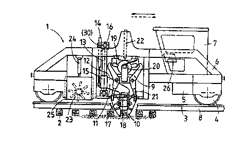
Referring now to the drawing and first to FIGS. 1 and 2,
there is shown mobile machine 1 for tamping ballast under
ties 2 of railroad track 3. The machine comprises machine
frame 6 and spaced undercarriages 4 supporting the machine
frame for mobility on railroad track 3 in an operating
direction. The machine has its own drive 5 and carries
operator's cab 7. Respective ballast tamping assembly 9 is
associated with each rail 8 of track 3. Each ballast
; tamping assembly is mounted on machine frame 6 and comprises
a tamping tool carrier vertically adjustable on the machine
frame by drive 22, pairs of vibratory and reciprocatory
tamping tools 21 immersible in the ballast upon vertical
adjustment of the tamping tool carrier, and drives 19, 20
for vibrating and reciprocating the tamping tools. A11 of
this structure is conventional. According to the invention,
vertically adjustable device 11 for gripping and
transversely positionining a respective tie 2 is associated
with ballast tamping assembly 9 and drive 14 is arranged for
vertically adjusting the device.
As shown in the drawing, device 11 comprises adjustable
tie gripping elements consisting of pivotal clamps 10
constituting tie gripping means 17 and drive means 18
-6-
32
linking the clamps for adjusting them between a tie gripping
and release position. Tie clamps 10 and drive means 18 are
mounted on carrier body 12 and guide body 15 is affixed to
the carrier body, the carrier body extendlng obliquely from
the guide body to the clamps and drive means in a vertical
plane. Respective guide posts 13 and 16 extend vertically
and transversely for guidingly supporting guide body 15 for
vertical and transverse adjustment. Vertical adjustment
drive 14 is a cylinder-piston drive whose cylinder is
affixed to an upper portion of guide body 15 and further
drive 30 is connected to the guide body for transverse
adjustment thereof 7 the adjusting drives connecting the
guide body to machine frame 6. The vertical and transverse
adjustability of tie gripping means 17 provides great
mobility and adaptability to the device for gripping the tie
and for displacing it transversely with respect to the
railroad track for proper positioning of the tie, the
reaction forces generated by the tie displacement being
advantageously transmitted to the robust machine frame of
the machine. Depending on the length of the transverse
displacement path, an old tie may be withdrawn completely
from the track and a new tie gripped and inserted in its
place whereby the tie positioning device becomes a tie
replacement device. The oblique extension of the carrier
body enables the rigid guide posts to be connected to the
machine frame ahead of the ballast tamping assemblies in the
operating direction so that the adjustment of the tie
gripping and positioning device will not interfere with the
tamping tools. Furthermore, the projecting arrangement of
the tie clamps enables the operator to view the tie gripping
4~
operation freely.
Tie gripping and positioning device 11 is mounted on the
machine frame between ballast tamping assemblies 9, pivotal
tie gripping clamps 10 and the pairs of tamping tools 21
being arranged symmetrically with respect to a vertical
plane of symmetry extending transversely of railroad track
3. The symmetric arrangement of the tie gripping clamps and
tamping tools assures the automatic centering of the tamping
tools with respect to the gripped and repositioned tie. The
arrangement of the tie gripping and positioning device
between the ballast tamping assemblies makes it possible for
an operator in cab 7 to monitor the tie positionlng and tie
tamping operations.
As shown in FIGS. 1 and 2, a vertically adjustable
ballast broom device 23 is arranged on the machine frame for
sweeping ballast off respective ties 2 into an adjacent crib
defined between successive ties, and drive 24 links the
ballast brrom device to machine frame 6 for vertically
adjusting the broom device along vertical guide 25. The
broom device precedes the ballast tamping assembly in the
operating direction, beihg mounted on the machine frame
between the ballast tamping assembly and tie gripping and
positioning device ll. As shown in FIG. 2, broom device 23
comprises rotary ballast broom 27 extending over the width
of the railroad track and rotatable about horizontal axis 29
extending transversely thereto, and drive 28 for rotating
the broom. Drive 5 on the machine frame makes machine 1
self-propelled. All the drives on the machine are
remote-controlled from control panel 26 in operator's cab
7. A self-propelled machine with such a ballast broom
--8--
~Z5~4~
arrangement enables ballast to be removed from the ties and
to be smoothed in the succeeding cribs, or to have excess
ballast to be swept into the next crib so that there is
always a uniform amount of ballast available for tamping.
The operation of machine 1 will be described hereinbelow
in connection with an operation in which tie gripping and
positioning device 11 is used for withdrawing an old tie and
inserting a new tie:
As soon as an operating site has been reached by the
machine, drive 5 is actuated to propel machine frame 6 into
a position wherein tie clamps 10 are centered in relation to
tie 2 to be pulled. At the same time, drive 30 is actuated
to move tie gripping and positioning device 11 laterally
into a position shown in dash-dotted lines, which is
opposite to the tie withdrawal direction indicated by arrow
31. While tie clamps 10 are spread apart, drive 14 is
actuated to lower tie gripping means 17 to the level of the
tie and adjustment drive 18 is then actuated to pivot the
tie clamps into clamping engagement with the tie. Drive 30
is then actuated to move the gripped tie in the direction of
arrow 31 until tie gripping and positioning device 11 has
withdrawn tie 2 laterally from track 3 to a position in
which tie gripping means 11 is immediately adjacent ballast
tamping assembly 9. At this point, tie clamps are opened
again and the tie gripping and positioning device is
retracted into the end position shown in dash-dotted lines.
The device is then actuated again to withdraw the tie
further and this operation is repeated until the tie has
been withdrawn from track 3 to a lateral position whence it
may be readily removed by operating personnel on the
_g_
l2S~'~492
shoulder of the track. Immediately thereafter, the same tie
gripping and positioning device may be used for the
insertion of a new tie simply by reversing the direction of
lateral adjustment of the device. For this purpose, the
operating personnel will take a new tie stored on the track
shoulder and will place it in the space just evacuated by
the withdrawn tie so that a leading end of the new tie comes
to rest in a position wherein the tie clamps may engage it,
possibly after displacing any excess ballast from this space
to the adjacent cribs, whereupon tie gripping and
positioning device 11 is operated in the reverse direction
until the new tie has been fully inserted in track 3.
If there is no need for a tie replacement and a loose
tie has merely become misoriented, it is only necessary to
actuate drive 30 of tie gripping means 17 to grip the tie
and to actuate drive 5 to propel the machine frame until the
tie has assumed its correct transverse position for
subsequent tamping.
In a further operating stage, drive 28 is actuated to
rotate ballast broom 27 and, after drive 24 is actuated to
lower ballast broom device 23 onto tie 2, drive 5 is
actuated to propel machine 1 toward the newly inserted or
properly positioned tie. During this movement of the
machine, the ballast is swept from the cribs alongside the
longitudinal edyes of the newly inserted or properly
positioned tie and any ballast on this tie is swept off it.
Subsequently, ballast broom device is raised and machine 1
is propelled in the operating direction until tamping tools
21 of ballast tamping assemblies 9 are centered over the
newly inserted or properly positioned tie. Drives 22 are
-10-
32
now actuated to lower the tamping assemblies for immersion of
the tamping tools in the ballast and tamping tool
reciprocating and vibrating drives 19, 20 are actuated to tamp
the ballast under the tie. The tie may be fastened to rails 8
either before or after tamping, for example by driving
fastening spikes into the tie.
It is also possible to use tie gripping and positioning
device 11 of machine 1 merely for the final stage of a tie
insertion in a tie replacement installation in which groups
10 ~ of, say, three adjacent ties are replaced in an existing
track, in which installation a tie insertion device has
partially inserted a group of new ties and tie gripping and
positioning device 11 only accomplishes the final stage of the
insertion and proper positioning of the new ties. Such a
tamping machine at the end of a tie replacement apparatus is
of particular value when the apparatus is used for replacing a
considerable number of groups of ties in a long stretch o~
existing track.
Machine 1 may also be used simply for sequentially
tamping consecutive ties 2 of track 3, for example following a
track leveling, lining and tamping machine. On the other
hand, used alone, a work crew may precede the machine to note
damaged or loose ties. The spikes will be removed from such
ties and they will preferably be marked so that the operator
in cab 7 will be able to notice them as the tamping machine
advances from tie to tie. Upon noticing a marked tie, the
operator will interrupt the tamping operation and
4 -11-
will operate tie gripping and positioning device ll in the
above-indicated manner either to replace the damaged tie or
to position the misoriented tie properly, whereupon the
tamping operation is resumed.
FIG. 3 illustrates mobile track leveling, lining and
- tamping machine 32 comprising machine frame 33, spaced
undercarriages 35 supporting the machine frame for mobility
on railroad track 38 in an operating direction indicated by
arrow 44. Drive 39 propels the machine and the machine
frame carries operator's cab 34 at a rear end thereof and
power plant 40 at a front end for supplying power to the
operating drives of the machine. Ballast tamping assembly
43 is mounted on machine frame 3 and comprises a vertically
adjustable tamping tool carrier, drive 42 vertically
adjusting the tamping tool carrier. Pairs of vibratory and
reciprocatory tamping tools 41 are immersible in the ballast
upon vertical adjustment of the tamping tool carrier and
drives are provided for vibrating and reciprocating the
tamping tools. Vertically adjustable device 50 for gripping
and transversely positioning a respective tie 36 of the
track is associated with the ballast tamping assembly, tie
gripping and positioning device 50 and tamping assembly 43
being mounted sequentially in the operating direction on
machine frame 33 between undercarriages 35. Drive 52
vertically adjusts the tie gripping and positioning device.
Track leveling and lining system 49 and track lifting and
lining unit 45 controlled by the system are mounted on
machine frame 33. Unit 45 is arranged immediately preceding
the ballast tamping assembly and comprises lifting and
lining tools 46, 47 engaging rails 37 of track 38. Lifting
-12-
drive 48 connects unit 45 to the machine frame. As shown, tie
gripping and positioning device 56 and track lifting and
lining unit 45 are arranged sequentially in the operating
direction, unit 45 being mounted between device 56 and ballast
tamping assembly 43.
The tie gripping and positioning device comprises
vertically adjustable and obliquely downwardly extending
carrier body 53 whose lower end carries tie gripping means 54
comprising tie clamps 56 operated by drive 56. Drive 57 is
connected to carrier body 53 for transversely displacing the
carrier body with the tie gripping means. The sequential
arrangement of the tie gripping and positioning device, the
track lifting and lining unit and the ballast tamping assembly
enable the ties to be tamping immediately after they have been
properly positioned in a leveled and lined position.
FIGS. 4 and 5 illustrate an operating unit 62 useful for
incorporation in a continuously advancing mobile tie
replacement apparatus 70. The operating unit comprises tool
carrier frame 63 and undercarriage 64 with flanged wheels
supporting one end of the tool carrier frame on railroad track
67 consisting of rails 65 fastened to ties 66. It further
comprises vertically adjustable ballast broom device 73
arranged for sweeping ballast off respective ties into an
adjacent crib defined between successive ties, drive means 74
for vertically adjusting the broom device, and ballast tamping
assembly 61. The ballast tamping assembly comprises a
vertically adjustable tamping tool carrier, drive 71 for
-13-
I
12~
vertically adjusting the tamping tool carrier, pairs of
vibratory and reciprocatory tamping tools 60 immersible in
the ballast upon vertical adjustment of the tamping tool
carrier, and drives 58, 59 for reciprocating and vibrating
the tamping tools. The ballast tamping assembly succeeds
the ballast broom device in the operating direction. Drive
68 connects an opposite end of tool carrier frame 63 to
machine frame 69 for longitudinally displacing the tool
carrier frame relative to the machine frame. This opposite
tool carrier frame end is formed by a central pole. AS
shown in FIG. 4, machine frame 69 has an upwardly recessed
portion between the undercarriages (not shown) supporting
the respective ends of the machine frame for mobility on
railroad track 67, operating unit 62 being arranged in the
recessed machine frame portion. Also, as in the embodiment
of FIGS. 1 and 2, the machine frame may carry a drive
whereby the machine is self-propelled. Supporting
undercarriage 64 of tool carrier frame 63 has its own brake
system 72. As shown in FIG. 5, the ballast broom device
comprises rotary ballast broom 75 rotatable about horizontal
axis 77 by drive 76 and extending across track 67. The
broom has tubular sweeping elements 78 projecting radially
from broom axis 77.
Such a longitudinally displaceable operating unit housed
in an upwardly recessed machine frame portion of a machine
79 incorporated into a continuously advancing tie
replacement apparatus enables effective tamping of the newly
inserted ties to be effected intermittently while the
apparatus proceeds non-stop along the track. Before
tamping, ballast broom device 73 is lowered by drive means
-14-
~ ~2~6~2
74 until broom 75 contacts ties 66 and the broom is rotated
to sweep the ballast into the adjacent crib. After tamping
the tie, the ballast broom device may be lifted or, if
desired, it may remain in its lowered position while mobile
apparatus 70 continuously advances. As sketchily indicated
at the right of FIG. 4, the entire operation of the tools on
unit 62 may be controlled by an operator in a cab within
view of the unit. After completing the tamping of each tie,
drive 68 is actuated for rapidly displacing the unit from
its rear position shown in dash-dotted lines to its forward
position in which the tamping of the next tie is initiated.
FIG. 6 illustrates track leveling, lining and tamping
machine 80 incorporating ballast broom device 94. The
machine has frame 81 carrying operator's cab 82 and power
plant 83. Undercarriages 84 support the machine frame.
Drive 88 propeIs the machine along railroad track 87
consisting of rails 86 fastened to ties 85 in an operating
direction indicated by arrow 99. Vertically adjustable
ballast tamping assembly 91 having pairs of vibratory and
reciprocatory tamping tools 89 is mounted on machine frame
81 between undercarriages 84 and vertical adjustment drive
90 connects the ballast tamping assembly to the machine
frame. Furthermore, track lifting and lining unit 92 is
connected to machine frame 81 by vertical adjustment drive
93, preceding the ballast tamping assembly in the operating
direction. Vertically adjustable ballast broom device 94
comprising rotary ballast broom 95, in turn, precedes
ballast tamping assembly 91 and track lifting and lining
unit 92, and vertical adjustment drive 96 connects the
ballast broom device to the machine frame for vertical
adjustment thereof along a vertical guide. Track leveling
reference system 98, which controls the operation of track
leveling by unit 92, is supported on railroad track 87 by
rail sensing rollers 97. As fragmentarily indicated at the
left of FIG. 6, track leveling, lining and tamping machine
80 is preceded by a ballast cleaning machine 102 supported
by undercarriages 100 on track 87 and propelled therealong
by drive 101,
Such a track leveling, lining and tamping machine
1~ advancing intermittently from tie to tie is particularly
adapted for use with a continuously advancing ballast
cleaning machine. The ballast broom device sweeps the
redistributed cleaned ballast, some of which rests on the
ties and which is not uniformly distributed in the cribs,
into the cribs for uniform distribution thereof. If there
is excess ballast in one crib, the rotary broom will sweep
it over the next tie into the adjacent crib. In this
manner, sufficient and substantially uniformly distributed
ballast will be available in each crib for tamping under the
ties, thus producing uniform and stable tie tamping.
-16-