Note : Les descriptions sont présentées dans la langue officielle dans laquelle elles ont été soumises.
A booklet or the like
D SCRIPTION
Technical Field
The present invention relates to a booklet, a
folder, covers or the like and a method and apparatus
for their manufacture. More specifically, the invention
refers to a folder or the like, comprising two
substantially parallel covers, which with the aid of
crease lines are connected to a spine on the inside of
which and solely between the creas~ lines there is
attached a strip of binding agent, the strip being
intended to be activated for providing adhesion between
it and one edge of a sheaf of papers inserted between
the covers.
~ackground Art
Booklets, etc. of the kind described in the
introduction are already known in many embodiments.
Examples of such booklets and how they are manufactured
and used are to be found inter alia in the US patent
specificationsJ3 973 787, ~ 129 471, 4~289 330 and
4 367 061~
In the last-mentioned specification there is
; 20 described and illustrated how a glue strip is attached
to the inside of the booklet spine substantially
simultaneously with crease lines being formed on either
side of the strip, this giving, inter alia, the advantage
that the glue strip is very carefully oriented between
the crease lines, whereby folding the booklet along
them can be performed without obstruction from the glue
strip, and it is ensured at the same time that the edges
of all the sheets of paper later inserted in the booklet
are joined to the melted glue strip along the entire
length of the spine, while at the same time the booklet
in the area of the glue strip is given, both inside and
outside, a high-quality implementation without
irregularities and other deficiencies deleterious to
lts appearance.
~2~
A disadvantage burdening the booklet according
to the US parent specification 4 367 061 is, however,
that outside sheets in a sheaf which is insarted in
the booklet for joining to the inside of the booklet
spine may come between the glue strip and the covers,
particularly for t~e reason that the covers are not
usually parallel, but diverge from the spine. This
results in at least the outer sheets not completely
coming into contact with the glue strip during the
binding operation, in turn resulting in that they can
come loose from the finished booklet.
To remove the disadvantage mentioned in the
previous paragraph it has been proposed to apply binder
and/or guide means on the insides of the covers in the
vicinity of the creasing lines between the covers and
the spine, as is illustrated in the three first-mentioned
of the cited US patent specifications, thus to ensure
that all sheets in the sheaf will come into engagement
against the strip on the spine. In the case where bind-
ing agent is used for thi`s purpose, only the two outmostshèets in the sheaf will be joined to it, wfile the next
outmost sheets and possibly further sheets in the sheaf
which have come outside the glue strip will not be bound.
Furthermore, the use of binding agent on the covers means
an increased cost and a more complicated manufacturing
method. In the case where guide means are used, the
available space between the covers is decreased and an
unutilised gap occurs on either side of the sheaf. In
the case where the binding agent on both covers and on
the strip forms a cohesive band, creasing along the
creasing lines or their preparation is made more
difficult as well as there being the consumption of an
unnecessary large amount of binding agent.
Disclosure of Invention
It is one object of the present invention at
least partially to remove the disadvantages with
:
6 ~
65~66-31
previous folders, booklets, covers and the like, as well as the
disadvantages with the methods and apparatus for their
manufactureO
Thus, according to a first broad aspect of the present
invention, there is provided a booklet, folder, wrapper or the
like comprising two substantially parallel covers, which are
united with a spine by crease lines, there being attached a strip
of binder on the inside of said spine and solely between the
crease lines, said strip being intended for activation such as to
achieve adhesion between it and one edge of a sheaf of sheets of
material inserted between the covers, characterized in that in the
booklet or the like with the sheaf not yet inserted between the
two covers, two opposing longitudinal side edges of said strip are
united with the covers.
According to a second broad aspect of the present
invention, there is provided a method of producing a booklet,
folder, wrapper or the like, comprising two substantially parallel
covers which are united with a spine by crease lines, on the
inside of the spine and solely between the crease lines there
being attached a strip of binder, said strip being intended for
activation such as to provide adhesion between it and one edge of
; a sheaf of sheets of material inserted between the covers,
characterized in that the two opposing longitudinal side edges of
; said strip are united with the covers before the sheaf is inserted
therebetween.
According to a third broad aspect of the present
` invention, there is provided an apparatus for producing a booklet,
:
~2~6q~
65466-31
a folder, a wrapper or the like, and comprising two substantially
parallel covers, connected to a splne with the aid of crease
lines, on the inside of the spine there being attached a strip of
binder solely between the crease lines, said strip being intended
for activation to provide adhesion between it and one edge of a
sheaf of sheets of material inserted between the covers,
characterized in that it includes an apparatus for uniting two
opposing longitudinal side edges on said strip with the covers
before the sheaf is inserted therebetween.
Description of the Fiaures
Figures l and 2 are end views of a Eolder, a booklet, a
cover or the like (in the following designated booklet) according
to two embodiments in accordance with the present invention.
Figure 3 is a perspective view of a previously known,
unfolded booklet, which is used as starting product in
manufacturing the booklet in accordance with the invention.
Figure 4 is an end view of the booklet according to
Figure 3 in a folded condition.
Figure 5 is a perspective view obliquely from above of
an apparatus for producing the booklet according to Figure 1 or 2.
Figure 6 is an end view of a part of the apparatus
according to Figure 5 with a booklet inserted therein.
Figure 7 is an end view corresponding to the one in
Figure 6 but schematically illustrating a second embodiment of the
apparatus.
Figure 8 is a schematic end view illustrating an
alternative embodiment of the apparatus in accordance with the
3a
,
1~46 ~1
65466-31
invention.
Figure 9 is a view seen obliquely from above
illustrating an apparatus for producing a blank for the booklet
illustrated in Figure 1.
Preferred Embodiments
Two preferred embodiments of the booklet in accordance
with the present invention, as it is produced by one of the
apparatus illustrated in Figures 5 ~ 8, is illustrated in Figures
1 and 2.
\
3b
4 65466-31
In Figure 1 the folder is provided with two covers 1 and
2, and a spine 3, which can be made in one piece, e.g. from carton
or as separate sheets of carton and/or plastics, which are
connected in some suitable way to each other. A binding agent in
the form of a strip 4 is fastened to the inside of the spine 3.
The binding agent consists of such as thermoplastics, hot melt
glue or the like, which is in a solid state at room temperature,
and on heating to a given temperature melts to become more or less
liquid. The strip 4 has a substantially rectangular cross section
and is immediately inside the crease lines 5 and 6 between the
covers l, 2 and spine 3. These crease lines 5 and 6 are suitably
provided by creasing in connection with attaching the strip 4 to
the inside of the spine and forming the crease lines 7 and 8 at a
short distance from the lines 5, 6. A method and apparatus for
achieving creasing and the fastening of the strip is disclosed in
the US patent specification 4 367 061 and also in Figure 9. There
is thus achieved that the strip 4 is oriented exactly between the
lines 5/ 6 so that the subsequent folding can take place un-
obstructedly, without any obstruction from the strip and without
the covers bulging between the lines 5, 7 and 6, 8.
Both opposing longitudinal side edges 4a and 4b of the
strip 4, which are at right angles to the spine 3, are united with
the insides of the covers l and 2 in accordance with the
invention. This union is made in one or two possible ways: (l)
The strip may be fastened directly to the covers l, 2 by pressing
the sides of the covers against the side edges of the strip while
these edges are heated to a predetermined minimum temperature, or
by heating the side edges after the strip has been joined to the
~.~
4a 65466-31
spine only and so:Lidi:Eied; or (2) with the aid of some suitable
binding agent oE a different kind, which does not require heat.ing
Eor adhesion, eOg. a cold glue, being applied to the strip before
the covers are folded along the crease lines 5 and 6 in a
direction towards the strip 4.
~.~
6 ~
65466-31
After the union between the strip 4 and the covers 1 and
2, the latter will be substantially parallel and at right angles
to the strip 4, if the crease lines 5 and 6 have small transverse
extensions, and this is illustrated in Figure 1. If these crease
lines have greater extension the covers 1 and 2 will converge
somewhat from the strip, resulting in that the covers form guides
in the area of the lines 7 and 8 for a sheaf of papers inserted in
the booklet, and the risk of a sheaf with a thickness greater than
the width of the strip 4 being inserted in the booklet is reduced.
A modified embodiment of the booklet is illustrated in
Figure 2, and here the booklet mainly differs from the one in
Figure 1 by the strip, now denoted 9, having a trapezoidal-shaped
cross section (i.e. a cross section with two parallel sides and
two converging sides) with both the longitudinal non-parallel side
edges 9a and 9b united with the covers 1' and 2' and the parallel
sides of the trapezoid parallel to the spine. In this way these
covers, substantially between the lines corresponding to the lines
5, 7 and 6, 8 in Figure 1, will converge in a direction from the
strip 9 to form a well-defined guide for a sheaf of papers
inserted in the booklet and will prevent a sheaf that is too thick
from being inserted in it. In the case where the lines 5 - 8 in
` ~ Figure 1, and corresponding lines in Figure 2, are creased in the
way illustrated in the Figures with crease lines, which are convex
seen from the inside of the booklet, the outer sheets in a sheaf
inserted in the booklet are prevented from fastening on the crease
lines.
In the embodiment illustrated in Figure l, as well as
the one in Figure 2, the strip 4 or 9 can have an upper surface
~, ~
- ~2~
5a 65466-31
which is not entirely flat. This upper surEace can thus be
convex, concave or may have some other suitable contour. It may
also be provided with a centrally situated U or V-shaped recess
or several such
:: :
b,~
recesses with small transverse extension~ To achieve
the mentioned union between the strip 4 or g and the
covers 1 and 2, or 1' and 2' it is how ver necessary
for the side edges of the strip 4 or 9 to have such
large surfaces that the mentioned union can be made
and maintained. The height of these surfaces should
therefore not be less than about 1 mm in Figures 1
and 2.
In Figure 3 there is illustrated the starting
material used in manufacturing the booklet according to
Figure 1 or 2, and therefore the booklet illustrated
in Figure 1 will be the only one referred to in the
following. This starting material, which is
substantially flat, includes the covers 1, 2 and spine 3,
these being either united to each other or formed
integrally, the strip 4 fastened to the inside of the
spine and the crease lines 5 --80 The starting material
is known, and is illustrated in the above-mentioned
US patent specification 4 367 061, where there is also
illustrated an apparatus for manufacturing it.
; In Figure 4 the substantially flat material
illustrated in Fig. 3 is now illustrated folded along
the crease lines 5 and 6, the folding having been
achieved with such as the folding means illustrated in
the US patent specification 4 557 714. As will be seen
from Figure 4, the covers 1 and 2 in the vicinity of
~ the spine 3 are spaced from the side edges 4a and 4b
; of the strip 4, since the booklet material has distanced
- itself from the strip after folding, due to its
elasticity at the crease lines 5, 6.
If a booklet with the cross section illustrated
in Figure 4 where to be used for accommodating a sheaf
of papers, several sheets in this sheaf could be
inserted between each of the covers 1 and 2 and the
respective side edge 4a or 4b of the strip, the outmost
of these sheets would not then come into contact with
6~
the strip, and would thus not be attached to the booklet
in the subsequent activation of the strip, thus causing
the accompanying disadvantages accounted for in the
introduction. In the case where the strip comprises a
thermoplastic or the like, this activation takes place
- by heating the strip and allowing it to cool after the
sheets have sunk into the softened strip. A more detailed
description of the activation and an apparatus for
providing it is found in such as the US patent specifica-
tion 4 367 116.
An apparatus is illustrated in Figures 5 and 6for producing the booklet illustrated in Figure 1 or 2,
in Figure 5 the booklet being illustrated partially
inserted in the apparatus, and in Figure 6 entirely
inserted in the apparatus~ Before insertion the booklet
has been suitably folded to the configuration illustrated
in Figure 4.
The apparatus in Figures 5 and 6 includes a
stand 10 placed on a floor, and on the stand there are
mounted a motor 11, two upper plates 12 and 13 and four
lower plates, three of these plates 14 - 16 being visible.
The fourth plate is situated beside plate 16 and behind
plate 14. A plurality of pulleys 17 are rotatably mounted
on the upper plate 12 and 13 at mutual uniform spacing
in the longitudinal direction of the stand, this spacing
being less than the length of the booklet. The output
shaft of the motor 11 is also provided with a pulley 18.
With the aid of a line or cord 19 the pulley 18 drives
the pulley 17 illustrated farthest to the left in
Figure 5, this pulley then drivin~ the three nearest
pulleys 17 via a cord 20. Of the three pulleys 17 just
mentioned, both those furthest to the right in Figure 5
drive the remaining pulleys 17 via identical cords 21.
Pressure rollers are mounted on the shafts of
all the pulleys 17 and are accommodated in recesses in
the plate 14 - 16 and the fourth plate. The two nearest
pressure rollers 22 and 23 are illustrated in Figure 6,
6~
and the distance between such pressure roller pairs 22,
23 is less than the exterior width of a ~inished book-
let. In a zone (at a~ immediately above the rollers
22, 23 the distance between opposing plates 14, 15
and 16 and the fourth plate is just as great as the
exterior width of the booklet, whereas in a zone (at b)
above zone at the distance is substantially smaller.
The plates 14 and 15 are provided with electric heating
elements 24 and 25 along their entire length where zone
a merges into zone b.
When the booklet has been inserted between the
plates 14, 15 and both forward pressure rollers 22, 23
in the manner illustrated in Figures 5 and 6, the rollers
will drive the booklet through the apparatus while the
booklet is retained between the plates, due to each
roll pair squeezing the booklet via chamfered edges
urging the b~oklet upwards. During the forward travel of
the booklet, when the covers 1, 2 are pressed against
the side edges 4a and 4b of the strip 4, these side
edges are heated by the heating elements 24 and 25 via
the covers and spine so that the side edges become soft.
When the booklet leaves the gap between the plates 14
and 15 the side edges are so so~t that they adhere to
the covers 1 and 2, which are simultaneously pressed
against the side edges, this adhesion being made
permanent during the continued forward travel of the
booklet between the plate 16 and the fourth unillustrated
plate, these latter plates being insulated from the
plates 14 and 15 and cool the booklet, possibly by un-
illustrated cooling element. When the booklet leavesthe apparatus, the covers 1 and 2 are permanently united
with the strip 4.
The apparatus illustrated in Figures 5 and 6 can
be modified in different ways. For example, the pressure
rollers 22, 23 can be replaced by drive rollers for belts
which are in contact with the covers 1 and 2 along the
9 65466-31
whole of their length during travel through the apparatus.
Neither do the pressure rollers 22, 23 need to be driven, and they
can be merely rotatably mounted, thus not requiring the pulleys
17, 18, cords 19 - 21 and motor 11, the bookle-t then being taken
manually through the apparatus. In such an embodiment the
pressure rollers 22, 23 can also be dispensed with, and the covers
of the booklet can be pressed against each other merely by the
plates 14 - 16 and the plate behind plate 16, while the booklet is
pulled manually through the apparatus. In this case the folder ls
also pressed upwards manually, or is pressed upwards by a bolster
moun-ted between the sides of the booklet and against the strip 4.
Instead of the heating elements 24, 25, other heating means can be
used, such as hot air jets directed towards the side edges of the
strip 4.
Two elongate pressure blocks 26, 27 are illustrated in
Figure 7, their length somewhat exceeding that of the booklet i.e.
substantially extending along the entire length of the strip, and
they are movable to and away from each other at substantially 90
to the longitudinal direction of the strip. After inserting the
booklet between the separated blocks 26, 27 they are urged towards
each other to press the covers 1, 2 against the side edges ~a, 4b
of the strip 4, so that the booklet is given the configuration
illustra-ted in Figure 1 or 2. Before the blocks are moved
together, the side edges can have been provided with some suitable
binder, e.g. a pressure-sensitive glue, which adheres the covers
in the pressing procedure mentioned. The union between the side
edges and the covers can also take place by heating and subsequent
~cooling of the strip side edges, e.g. by the blocks 26, 27 being
,~i~l, iB
9a 65466-31
provided with heating elements corresponding to those illustrated
in Figure 6 and by the provision of some suitable cooling means
after the blocks. If the strip has a rectangular cross section
and its edges are heated during the pressing operation, the blocks
may be
6-~
1 0
formed such that the strip is deformed and the booklet
is given the configuration illustrated in Figure 2.
According to a further embodiment of the
apparatus in accordance with the invention, which is
illustrated in Figure 8, the hot yet folded booklet
illustrated in Figure 3 can be folded simultaneously
with the covers 1 and 2 being united with the side
edges 4a, 4b of the strip 4, even though the folder is
not provided with creased lines. In this case the book-
let is placed on a substructure 30, provided with aslot 31, somewhat wider than the strip 4, so that the
strip 4 is immediately above the slot and facing up-
wards. A punch 32, which is just as wide as the strip 4,
is given a movement downwards in Figure 8 such as to
press the strip 4 and spine 3 downwards in the slot,
thus causing the covers 1 and 2 to be folded upwards
along crease lines formed immediately adjacent either
side. When the spine comes into engagement against the
bottom of a recess 33, connecting up -to the slot 31
and formed in a plate 34 insulated from the substructure
30, the covers 1 and 2 being pressed against the side
edges 4a, 4b of the strip, said edges are heated by the
heating elements 35 and 36 so that the edges at least
partially melt. When the punch 32 and booklet are taken
back upwards to a position where the side edges 4a and
4b are in the slot 31, the side edges are cooled by
the cool or cooled side walls of the slot. After
required cooling, the punch and booklet are taken still
further upwards, whereupon the finished booklet is
removed.
Instead of allowing the apparatus according to
Figure 8b to include heating elements 35, 36 and plate
34,glue can be applied to the side edges 4a and 4b
before, or in connection with, the not yet folded book-
;~ 35 let being placed on the substructure 30, the covers 1
and 2 then being folded along the side edges of the
strip 4 and united with th-ese when the punch 32 presses
the booklet down into the slot 31.
~2~
A still further embodiment of the apparatus
in accordance with the invsntion is illustrated in
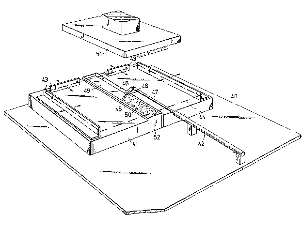
Figure 9. The apparatus comprises a substructure 40,
on which there is mountsd a plate 41 and a spraying
means 42. The plate 41 is provided with guide rails
43, which are adjustable in the horizontal plane,
these guide rails being intended to align a (carton)
blank 44 for registering with creasing edges 45 and 46
fastened to, and projecting above the substructure.
The spray means 42 comprises a piston cylinder device,
the piston rod 47 of which is connected to a spray jet
48, which is supplied with liquid glue (such as hot
melt lim) in a manner not illustrated. After the piston
rod 47 is moved from one end to the other end of the
plate 41, with the jet 48 situated directly above the
trough 49 formed by the edges 45 and 46, and has
deposited therein a predetermined quantity of binder 50,
the blank 44 is laid between the guide rails 43. A
press pillow 51 mounted above the plate 41 is then
- 20 lowered to press against the blank 44, thus causing the
edges 45, 46 to form crease lines in it. Simultaneously
with this, or immediately afterwards, the blank 44 will
come into contact with the binder 50, which is in the
trough 48 in the form of a more or less liquid strip,
this strip then adhering to the blank. The blank 44
and strip now form an unfolded booklet similar to the
one illustrated in Figure 3, but with the difference
that the strip still has not completely solidified.
Immediately after adhesion by the binder 50
- 30 (the strip) to the blank 44, the latter is folded to
form the booklet illustrated in Figure 1 or 2, the
remaining heat in the strip being utilised during
folding to enable the side edges 4a and 4b of the strip
to adhere firmly to the covers 1 and 2. This folding
procedure may take place using any one of the methods
described above with one of the apparatuses described
6~
above, either in the immediate vicinity of, or
combined with the apparatus illustrated in Fig. 9.
Such a combined apparatus can include: a) the bottom 52
in the trough 49 between the edges 45 and 46, this
5 trough being displaceable vertically upwards from the
position illustrated in Figure 9, taking with it the
not yet folded bookle~ after the press pillow 51 has
been removed sufficiently far from the plate 41, and
b) the substructure 30 with the slot 31 in Figure 8,
10 when the bottom 52 in Figure 9 may be said to correspond
to the punch 32 in Figure 8, if this figure is viewed
upside down. In an apparatus of the last mentioned kind,
it is important that the binder 50 is not allowed to
solidify completely before olding takes place, and
15 displacement of the bottom 52 must take place
immediately after the binder 50 is capable of carrying
; the blank 44 (covers 1 and 2 and spine 3) or means must
3 be arranged for carrying the blank in some other way.
The creasing edges 45, 46 may be heated to reduce the
20 risk of cooling taking place too quickly or for reheat-
ing the cooled strip.
It will be seen from the drawings and the
description of the present invention that different
modification and embodiments thereof are possible.
25' Further modifications and embodiments are also possible
without departing from the inventive concept.
The invention is thus limi~ed solely by what
is disclosed in the claims.
.
:
:
:,