Note : Les descriptions sont présentées dans la langue officielle dans laquelle elles ont été soumises.
7~
~ .
HIGH SPEED M~NETIC DISK CONTACT RECORDING SYSTEM
BACKGROUND OF THE INVF~TION
FIELD OF THE INVENTION
This invention relates in general to magnetic recording
systems and, in particular, to a magnetic disk recording
system in which the magnetic transducer is in contact with the
storage medium at operatlng speed.
DESCRIPTION OF TH~ PRIOR ART
It has been recognized since the early days of moving
magnetic storage systems that contact recording is desirable.
R. L. Wallace, Jr. established the space loss relationship in
his paper "The Reproduction of Magnetically Recorded Signals",
Bell System Technical Journal, October, 1951, pp 1145-1173.
This paper defines the spacing loss (i.e. loss of read signal
amplitude) in terms of the distance d between the magnetic
read head and the surface of the recording medium and the
wavelength of the recorded signal.
Although contact is known to be a key factor in audio and
video recording systems as well as floppy disks, in contrast,
contact recording systems for high performance moving magnetic
storage systems have not been widely used. The reason for
this is that, in the moving magnetic recording system, the
transducer must be capable o~ running on the same track for
extended periods of time without damage to the recording
medium. The contact recording systems for high speed moving
magnetic recording that have been built have had the problem
of excessive wear of both the magnetic transducer and the
magnetic recording medium.
SA986025
70~a
,. .
U.S. patent ~,225,892 to Bassett et al discloses a
magnetoresistive read head which is deposited onto a single
crystal sapphire substrate which has a particular
crystallographic orientation as the wear surface.
IBM TDB June, 1984, p 496 by Kehr et al discloses a
ferrite magnetic head having at least one surface formed of a
single crystal manganese-zinc ferrite. The surface is etched
to form a smooth pore-free surface.
The une~amined published Japanese patent application
57-207408 discloses the use of a single crystal corundum as a
substrate for a magnetic head.
U.S. patent 3,919,717 to Cullen et al shows a wear
resistant surface for magnetic heads comprising diamond
particles in a matrix of a so~ter material such as rhodium,
for example.
None of the references disclose a contact recording
system which utilizes a single crystal material having the
physical characteristics required to hold the slider in
contact with the recording medium without external force
during high speed recording and sensing operations.
SUMMARY OF T~ INVENTION
It is therefore the principal object of this invention to
provide a contact recording syste~ for a high speed moving
magnetic storage system in which an attractive force is
generated so that high density recorded data can be reliably
written and sensed without excessive wear to either the
magnetic transducer or the recording medium.
In accordance with the invention, a high speed magnetic
disk recording system is provided in which the recording
medium comprises a substrate having a magnetic coating
SA986025 2
z~
.ereon, and a magnetic recording transducer in physical
contact with the magnetic recording medium. The magnetic
recording transducer comprises a substrate of a single crystal
material having a high thermal conductivity, a low friction
coefficient and a high surface energy. Means are provided to
produce relative motion between the magnetic recording
transducer and the recording medium whereby an attractive
force is generated which maintains the magnetic recording
transducer in contact with the recording medium so that high
density recorded data can be rcliably written and sensed.
The foregoing and other objects, features and advantages
of the invention will be apparent from the following more
particular description of a preferred embodiment of the
invention as illustrated in the accompanying drawings.
BRIEF DESCRIPTION OF_HE DR~WINGS
Fig. 1 is a simplified block diagram of a magnetic disk
file embodying the present invention.
Fig. 2 is an enlarged top view showing the slider in
Fig. 1 in greater detail.
Fig. 3 is a section view taken along lines 3-3 of Fig. 2.
Fig. 4 is a section view of the slider with an alternate
embodiment of the recording medium.
Fig. 5 is a three dimensional view of an alternate
embodiment of the slider.
Fig. 6 is a bottom view of a further embodiment of the
slider.
Fig. 7 is a section view taken along lines 7-7 of Fig. 6.
Fig. 8 is a section view of another embodiment of the
slider.
SA986025 3
l~C3~704
DESCRIPTION OF THE PREFE RRED EMBODIMENTS
~ The present invention is described as embodied in a
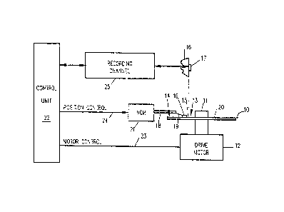
magnetic disk storage file as shown in Fig. 1. At least one
rigid rotatable disk, such as disk 10 is supported on a
spindle 11 and rotated by a disk drive motor 12. The magnetic
recording medium 15 on each disk is in the form of an annular
pattern of concentric data tracks having an inside diameter 13
and an outside diameter 14, as shown on disk 10.
At least one slider 16 is positioned in contact with the
magnetic recording medium 15, and each slider 16 supports one
or more read/write heads 17. The slider 16 is attached to an
actuator arm 18 by means of a suspension 19. The suspensions
19 provide a slight spring force which biases the slider 16
against the disk surface 20. Each actuator arm 18 is attached
to accessing mechanism such as a voice coil motor (VCM) 21,
for example. The VCM is a coil movable within a fixed
magnetic field, and the direction and velocity of the coil
movement is controlled by the current supplied.
As the disk 10 rotates, the slider 16 is moved radially
in and out so that the head 17 ma~ access different portions
of the disk surface 20 containing the data.
The above description of a magnetic disk storage file,
and the accompanying illustration of it in Fig. 1 are for
representative purposes only. It should be apparent that disk
files may contain a large number of disks and VCMs and that
each actuator arm may support a number of sliders. The
present invention of a contact recording magnetic disk storage
system is fully applicable to any such movable storage
apparatus, provided it is of the type in which the sliders are
in contact with the storage medium when at operating speed.
SA986025 4
:~Z~3~7 [)9~
. . .
The various components of the disk file are controlled in
operation by signals generated by control unit 22 which
includes internal clock signals, logic control circuits,
storage and a microprocessor. The control unit 22 generates
control signals to control various disk file operations such
as motor control signals on line 23 and position control
signals on line 24. The control slgnals on line 24 provide
the desired current profile to optimally move the selected
slider 16 to the desired track on the associated disk 10. The
READ and WRITE signals are communicated to and from readiwrite
head 17 by means of recording channel 25.
In accordance with the present invention, as shown in
Fig. 2, the slider 16 is positioned so that it is in contact
with the recording medium at normal operating speed produced
by relative motion, at a predetermined rate, between slider 16
and the surface 20 of the magnetic recording media 15 in the
direction indicated by arrow 26.
The magnetic read/write head 17 preferably comprises a
magnetic head formed by thin film deposition techniques such
as the thin film transducer described in commonly assigned
U.S. patent 4,190,872 to Jones, Jr. et al, for example. The
magnetic read/write head 17 is deposited on surface 28 of the
slider 16 which is substantially normal to the surface 27 of
the slider which is in contact with the recording medium.
It is a feature of the present invention that the slider
remains in direct contact with the disk surface even when the
relative motion between the slider and disk surface reaches
speeds of 20 meters per second or greater. This is
accomplished by an attractive force that is strong enough to
overcome the force of the film of air which is moving with the
disk surface which tends to force the slider away from the
disk surface. Th~ attractive force is believed to be produced
SA986025 5
7~g
~y a phenomenon known as contact electrification, although
others have attempted to e~plain the operation based on Van
der Waal's force. These phenomena have been known for years
although they are not well understood in their detailed
workings. However, by the use of specific materials'
characteristics for the slider and disk, it has been shown
that direct and continuous contact between slider and disk
surface can be assured without causing excessive wear to
either the magnetic transducer slider or the recording medium.
Contact electrification works on the principle that, when
two materials are rubbed together, electrical charge is
usually transferred from one material to the other. When two
insulators are involved, as in the present case, the -
electrical charge transfer is by way of an ion transfer from
one insulator to the other. It is also believed that a
temperature difference can result in charge transfer. If the
temperature of the two insulators differs, the two currents
resulting from the ionic transfer will not balance unless the
two thermionic currents alter. This results in the following
relationship:
where 2
~ U = U2 - U
A U is the energy difference and this factor is
proportional to the attractive force generated between the two
insulators. In the present case, the materials
characteristics are chosen so that the temperature of the
surface of the slider which is in contact with the recording
medium is a lower temperature than that of the recording
SA986025 6
1~47~4
~ edium. Should the materials characteristics be chosen so
that the temperature of the surface of the slider is greater
- then, greater wear and possibly destructive wear of the slider
would occur.
According to the present invention, as shown in Figs.
2-4, the slider is made from a single crystal material having
a high thermal conductivity, a low friction coefficient, high
surface energy and a material that is electrically
non-conductive. The slider material will be maintained in
direct contact with the disk surface during normal operation
; of the disk file due to the attractive force between the
slider 16 and the disk surface 20.
In a specific embodiment, slider 16 is made from a single
crystal diamond cut so that its crystalline orientation is
cllO> for the surface 27 which is in contact with the disk
surface 20. Another suitable material is a single crystal
cubic boron nitride. These materials have properties, when
; operated in contact with a magnetic disk of the type described
in greater detail below, which result in contact being
maintained between slider and disk surface without causing
excessive wear of either slider or disk surface.
The properties for the single crystal material include
high thermal conductivity, a low friction coefficient, a high
surface energy, and a high hardness. The thermal conductivity
enables the slider material to maintain a lower temperature
than the surface of the magnetic medium. The low friction
coefficient prevents wear of the surface of the magnetic
medium which is in contact with the slider. The high surface
energy prevents the slider surface from picking up
contamination which may be present in the system and the
hardness prevents plastic deformation and wear of the slider.
SA986025 7
709~
The single cr~stal diamond material was chosen since its
thermal conduc~ivity is high (ten times higher than single
crystal sapphire) at room temperature, its friction
coefficient is low (four times lower than single crystal
sapphire), its surface energy is high (six times higher than
single crystal sapphire), and its hardness is high (four and
one-half times harder than single crystal sapphire). The
comparisons are given to single crystal sapphire since this
material is the most attractive, by its characteristics, of
any of the materials disclosed in the prior art references
discussed in the Background of the Invention section of this
application. The other materials discussed there would
therefore be even less suitable for the present invention than
the single crystal sapphire material.
The single crystal material chosen should have a surface
energy above 5000 ergs/cm2, a high thermal conductivity, a
friction coefficient lower than .1, and a hardness above 3500
kg/mm2. Single crystal diamond and single crystal cubic boron
nitride are two materials which have the desired
characteristics.
The slider 16 is formed in the shape of an isosceles
triangle with the apex of the triangle along the line of
relative motion, which may be 3600 RPM, or greater, between
the slider and the surface of the recording medium. The
magnetic read/write head is formed on the trailing end of
slider 16 wlth respect to the relative motion. The triangular
shape of the slider and the position of the slider counteracts
any tendency for the slider to be moved off-track by the film
of air which is moving with the disk surface.
The recording medium comprises a substrate having a
magnetic coating thereon. In the specific embodiment shown in
Fig. 3, the recording medium 30 is a particulate magnetic
SA986025 8
7(~4
~isk. The recording medium 30 comprises a substrate 32 made
of an aluminum alloy, for example, having a particulate
magnetic coating 34 thereon. The magnetic coating comprises
magnetic particles in an epoxy-rcsin binder, and the coating
may also have alumina particles, if desired. The magnetic
coating is cured and buffcd to a chosen surface finish and a
small quantity of a liquid lubricant is deposited on the
surface 36 of the recording medium. It was unexpected that a
non-overcoated particulate disk could be used in a contact
recording system with the slider 16 in contact with surface 36
without exhibiting excessive wear. It is apparent that an
overcoated particulate magnetic disk may also be used, if
desired.
In the embodiment shown in Fig. 4, the recording medium
40 is a thin film magnetic disk. The recording medium 40
comprises a substrate 42 made of an Al-Mg alloy, for example,
an undercoat 44 of a material such as chromium, for example, a
magnetic coating 46 of a cobalt based alloy, for example, and
a protective overcoat 48 of a material such as carbon. The
slider 16 is positioned in contact with the surface 49 of the
recording medium 40 under normal operating conditions of a
disk storage file without producing excessive wear. In a
specific embodiment a triangular shaped slider comprising a
single crystal diamond 3 mm on a side and 1 mm thick was
operated in contact with a carbon overcoated recording medium,
and an attractive force of 18 grams was generated.
It is not necessary to have a slider which is made of a
single material in all cases provided that the material which
contacts the surface of the recording medium has sufficient
thickness to provide the required wear and thermal
characteristics. One embodiment of a composite slider is
shown in Fig. 5. In this embodiment the slider 50 comprises a
SA986025 9
lZ~7~
_hin sheet 52 of a singlc crystal material which forms the
surface 54 which is ln contact with the recording medium. The
thin sheet 52 of single crystal material is bonded to a slider
body 56 which is made of a suitable material such as a ceramic
comprising a mixture of Al203 and TiC. The suspension 19l is
attached to the slider body 56, and t:he magnetic read/write
head 17 is formed on surface 58 of the slider 50. If desired,
a non-conductive coating S9 such as alumina, for example, may
be deposited on surface 58 prior to cleposition of the magnetic
transducer 17.
In a further embodiment of the slider shown in Figs. 6
and 7, the slider 60 comprises a triangular shaped slider body
62 of a suitable material such as stainless steel, having a
plurality of contacting members 64 which contact the recording
medium. Contacting members 64 are bonded to the slider body 62
and members 64 are made from a single crystal material having
characteristics as stated above. The area of the contacting
members 64 is chosen compared to the area of pole tip area 67
of magnetic read/write transducer 68 so that sufficient
attractive force can be generated to maintain slider 60 in
contact with the recording medium during normal operation of
the disk file. The magnetic read/write transducer 68 is
centrally located.
In this case the transducer is ~ormed of a suitable
magnetic material such as a ferrite material and the
transducer 68 is bonded in position in central opening 69 in
slider body 62.
A further embodiment of the slider 70 is shown in Fig. 8
along with magnetic read/write transducer 71 in which the
slider body 72 compxises a first single crystal material such
as sapphire, for example, upon which is deposited an
epitaxially grown layer 74 of single crystal material. It has
SA986025 10
~2~
been found that a layer having a thickness of about 250
angstroms can provide the characteristics required to insure
contact between the surface 76 of slider 70 and the recording
medium 78.
While the invention has been particularly shown and
described with reference to a preferrcd embodiment thereof, it
will be understood by those skilled in the art that various
other changes in the form and details may be made therein
without departing from the spirit and scope of the invention.
SA986025 11