Note : Les descriptions sont présentées dans la langue officielle dans laquelle elles ont été soumises.
12~3~1
The present invention relates to a linear
actuator which is provided with a first level of position
control and a second level of position and overload control
and, more particularly, to an improved drive mechanism
having an anti-lockup feature for transferring rotary force
from an electric motor to axially move a connected
extension rod of the linear actuator to move a load.
Linear actuators are typically utilized in
situations where a thrust force is used for applying linear
motion. Examples of the utilization of such thrust force
is in the operation of lever arms, cranks, slides and valve
levers in industrial equipment. Such actuators are
utilized for alternately moving objects between
predetermined positional limits. The actuators can be
utilized for moving the movable member between positions
within such predetermined limits by the utilization of
appropriate feedback means.
According to the present invention a linear
actuator comprises, a housing; a drive screw rotatably
supported within said housing; a drive nut in threaded
engagement with said drive screw; a body tube assembly
connected to said housing and positioned about said drive
screw, said body tube assembly containing reaction force
surfaces for preventing rotation of said drive nut; an
extendible member having a load connecting member on its
free end and having the opposite end thereof connected to a
drive nut, said extendible member adapted for axial
movement so as to extend out of said body,tube; drive means
including an electric drive motor containing windings for
rotating said drive screw; said drive means including
intermediate gearing means for transmitting rotative torque
output from said electric drive motor to rotate said drive
screw, said intermediate gearing means including a lost
motion arrangement means for delaying rotation of said
drive screw for a predetermined interval during which a
drive pinion of said electric drive motor rotates through a
predetermined angular interval, said lost motion
arrangement means enabling said drive pinion to attain a
.'~, ~
~1`'~ , ~
~ 5361
rotational speed approaching a predetermined operating
speed before imparting rotative torque to drive said drive
screw through the intermediate gearing means, said lost
motion arrangement preventing lockup of the electric motor
and over-heating of the motor windings tending to occur
when an output load is connected to the load connecting
member, wherein said intermediate gearing means includes a
first intermediate gear and a second intermediate gear both
mounted intermediate the electric motor and the drive
screw, said first intermediate gear in contact with a drive
pinion and said second intermediate gear connected to
transmit rotative force to the drive screw, said lost
motion arrangement mear.s being formed between said first
and second intermediate gears to enable initial rotation of
said first intermediate gear under the driving force of the
drive pinion before imparting rotative force to the second
intermediate gear and thereby the drive screw.
Embodiments of the invention will now be
described with reference to the accompanying drawings in
which:
Figure 1 is a cross-sectional view of the
preferred embodiment of the linear actuator according to my
prior design set forth in the aforesaid United states
Patent 4,712,441;
Figure 2 is a partial cross-sectional view of the
anti-lockup drive mechanism according to the present
invention when employed in the linear actuator of Figure 1;
Figure 3 is an enlarged cross-sectional view of
the anti-lockup feature of Figure 2 removed from the linear
actuator; and
Figure 4 is an end view taken along the line 4-4
of Figure 3 depicting the lost motion mechanism in the
intermediate gear anti-lockup assembly.
Figure 1 is a cross-sectional view of a preferred
embodiment of the linear actuator described in my above-
identified copending U.S. patent application, wherein the
linear
12~3~
actuator 10 includes a body housing 12 formed with an upper
compartment 14, an intermediate motor casing opening 16,
and a body tube opening 18 at the lower end thereof. The
upper compartment 14 is closed by a cover plate 20 which is
sealed to the body housing 12 by a cover gasket 22. A gear
compartment face plate 24 is provided for sealing the drive
gear mechanism 26 within the body housing 12. A face plate
gasket 28 is provided for this purpose. Suitable socket
head screws are provided to secure the cover plate 20 and
face plate 24 to the body housing 12.
The internal operation of the linear actuator 10
is shown in Figure 1, wherein electric drive motor 44 which
is retained within motor casing 46 provides rotary power to
a drive pinion gear 48 which in turn transmits power
through an intermediate gear 50 to the main drive gear 52
which is journalled to the end of the drive screw 54 by a
Woodruff key 56. Rotation of drive screw 54 moves the
drive nut 58 axially within the body tube 60. The body
tube assembly 62 is formed by the external body tube 60
which is fitted into opening 18 and housing 12, the
internal drive screw 54, the drive nut 58 and an extension
rod 64 affixed to the outer side of drive nut 50 so as to
extend beyond the end cap 70 of the body tube assembly 62.
The drive nut 58 is secured against rotation by reaction
surfaces such as described in my United States Patent
4,712,441 dated December 15, 1987, inventor William F.
Abraham, assignee Brunswick Valve and Control Inc.,
entitled "Position Controlled Linear Actuator" which are
formed internally within body tube 60. Drive nut 58 may be
a square-sided nut as disclosed in U.S. Patent 4,712,441
and drive screw 54 is shown coaxially centred within the
extension rod 64.
Extension rod 64 is thus axially extendible beyond
the end cap 70 of the body tube assembly 62. This
extension rod 64 is secured at the outer end of the body
tube assembly 62 by an
~.;
l~
2953~
~nd ¢~p 70 which is ~o~e~ from a non-~errous metal which then
ac~s as a bushing a~d a seal.
The driven end of drlve ~rew 5~ is æupported ~y 8 pair
of ang~lar con~a~ bea~ings 72 ~nd 7~ which are supported within
a b~a~ing op~ning wi~hin body hou~lng 12. A main gear spacer 78
i~ provlded betwe~n the main d~lv~ gear ~2 and the two bearings
72 and 74. The ~ain drive ge~r l~ secur~d to th~ ~nd o the
driv~ sc~ew 54 by a ~l~x nut B0. The intermed$a~ gea~ 50
i~ retai~d on a dowel pin Y2 whiah is ~ournalleq ~etween
~earings 84 and 86. Thls lntermediat~ ~ear 50 has an out~ teeth
set ~B fo~ contactlng the d~iv~3 plnlon g~ar 48 and an inner set
~0 ~or ~ontaat wlth the main drive g~a~ ~2.
~he ~otor drlve ~h~ft 32 connected~o a ~otor core 93
i~ supported by a if ron~ bearing gq withln body h~using 12 and at
15 the outer end by a bearlng 96 which 1~ xetained in the motor
c~slng 4~. The motor s~ato~ ga is secured wlthin moto~ ca~ing 46
and i~ provided wlth a thermal sensing elemeAt 100 whiah together
wlth th~ switoh 102 ~orm~ an ove~load controller m~an~ 103 shown
~ohemat~aally. Th~ thermal ~n~ing elem~nt 100 csn i~dir~ctly
co~trol the ~wltch 102 a~ ~hown. Al~o, the ~her~al ~eA~lng
element 100 and swi~ch 102 can pre~erably be combined into a
~inglo b~-m~talllc swit~h su~h as di~clo~ed in u.s. Patent No.
3, 219, ~56 ~o ~unwiddle~
Motor ~asing 4~ aled wlthin opening 1~ and housing
Z5 12 by an o-~iny.
A oapaoitor ~ub-assembly 104 læ provided wlthin
compa~tment 14 ln orde~ to provlde for chsng~ of pha~ between
the wlndlngs ln motor 44 to effec~ ~he ln~tant rever~al of
direction of rota~ion. Motor ~4 ~ preferably a single phase
30 motor and is ~onne~;:t~d to the capacitor sub~assembly by, a
53~1
connection terminal 106 as shown. The drive pinion gear,
intermediate gear and the main gear then comprise the drive
means of the linear actuator.
During operation of the axial movement of
extension rod 64 between the terminal stroke limits, the
electric drive motor 44 is utilized to provide rotational
power through the drive gear mechanism 26 so that
rotational power is delivered to drive screw 54. A limit
switch assembly (not shown) described in detail in my U.S.
Patent 4,712,441 can be set so that power to the electric
drive motor 44 is interrupied just prior to the drive nut
58 reaching either of the two terminal positions which
limit its stroke. In the event that the limit switches
fail, the drive nut 58 will come into contact with either
the back stop 108 or the front stop 110. Mating back stop
reaction shoulder portion 112 is provided on drive nut 58
to provide a complementary abutment to the reaction
shoulder 114 on the back stop 108. Back stop 108 is
secured to the inner end of drive screw 54 by a set screw
116 which rests in a mounting slot 118. A similar reaction
shoulder 120 is provided for front stop 110 for co-action
with a mating reaction shoulder portion 122 secured to the
front face of drive nut 58. Both the back stop 108 and the
front stop 110 are secured to and rotate with the drive
screw 54. A retaining flex nut 124 is provided for
retaining front stop 110.
The abutment shoulders 114 and 120 and the
shoulder portions 112 and 122 on the drive nut 58 thus
function to restrain the movement of drive nut 58 relative
to drive screw 54 so that the actuator stroke mechanism
which is provided by the body tube assembly 62 is not
jammed at the ends of the extension rod stroke when the
power to the drive motor 44 has not been interrupted by the
limit switch assembly. In such an event, as
.
53 ~1 ~ J
illustrated in Figu~e l, the driv~ nu~ 5~ will come into a~utment
contsct with the back etop 108 with ~ ~a~y g~p 126 remaining
batween ~he abutment shoulde~ exten~ion 112 and t~e bsck stop
108. Contin~ed op~rat~on o~ d~ive motor 44 will cause the ~tatox
coil~ ga to h~at up beyond th~ p~edetermined temperature whioh i~
~en~ed by ~h~3 the~mal elem~n'c 100. The overload c:ont~olle~ means
103 then operat~s to disengage th~ elsctric powe~ supply to motor
44.
In the event th~t the ~ nsion rod 64 ls prevented
from mov~ment durlng th~ axia~ movement of drive nu~ 5~, ~his
~ame ov~rhe~ting of th~ mo~o~ 8tator winding will occur whl~h
wlll then re~ulk ln the ~leatria power being interrupted fr~m the
drive motor 44~ Th~, the overloa~ con~ol me~ns 103 funations
~oth at the te~mi,nal limi~s o~ the axial movement of ext~ns~ on
rod G4 as well as within tho~e limit~ in the event o~ an ove~load
thrust oondition.
~he ext~nsion rod 64 i~ fitted with a load ~onneator
125 whi~ has lnternal ~hreads 127 ~or oonneatin~ wlth the load
~no~ ~hown). A clevi~ bra~k~t 128 ~not ~hown ~n F~gu~ 1) on the
oppo~ite end o~ ~h~ liflear ~ctustor p~ovide~ a plvotal ~onneotion
~o a reaotion ~upport surf~ae. The clevis ~r~cket ls secured to
~he gear compartm~nt ~ace plate 24 by so~ke~ head c~p ~crews 13~
and 132 wh~h ~e balanced by a corresponding cap æcrew pair (not
shown ) .
~1~ear qctuator~ ~uch a~ th~ type described above
usually lnclude the ele~ri~ moto~ ~hi~h is ~onne~ted to the
d~ive screw throush a drive means which u~illæe~ either ~ ~ear
t~aln or a drive belt. In the case of a drive me~hani~m in ~he
form of a g~r ~raln, and wlth referenoe to my a~tuator des~ibed
~ove, th~ d~ive pinion gear 4B is mounted upon an ou~pu~ sh~ft
S
2~ 5 3&~
of drive motor 4~. The intermediate gear 50 which inolud~ ~
lar~er diamet~r gear 51 pre~ ked on~o a hub portion 50R
~hereo~ ~n~lude~ th~ ou~r ~ee~h ~et 8~ in direct mesh with drive
pln~on gea~ 4B. ~n tu~n, the teeth o in~e~ ia~e ~ear S0 are
5. in di~ect mesh wlt~ ma~n d~iv~ ~ear S~ for impa~ting axial
movement to dr~v~ nut 5a and ther~aby extens~on rod 64.
One problem pre~ent in my a~oresa~d lin~ar aatuator and
ln other linear actuator~ having a d~ive ~echani~m in ~he ~orm of
a gea~ traln i~ tha~ upOn in~tially actu~tlns the drive motor 44
to longitudlnally a~van~e the d~lve nut 58 throu~h th~ ge~r train
4~,50,52 there ls 2 tendency ~or th~ d~ive ~e¢h~ni~ to ~o~kupll
~lnc~ the motor drlve ~ha~ 92 has not a~t~i~ed a speed
approa~hing operatlng speed and therefo~ ~ay. not havs developed
sufficlent torque~to ove~ome the lnertla o~ the driven system,
i.e., the gea~ t~aln 4~,50,52, drive screw 54, drlve nut 58,
exten~ion rod 64 and an ou~pu~ load, if any, ~onnecte~ to and
driven by th~ linear a~tuator. Frequentl~ lockup" occurs when
the linear aatuator conne~:ted to ~n output load (e.g., a hopper
aon~a ~ nlng ~ine m~t~rial ) ~ 9 idle i~or any length oi~ tl~e . Loaku~
20 may ~lso o~ in ~he event that op~r~tion o~ the linea~ a~l:uator
~top~ at a tlm~ when the d~ive nu~ i9 ~t an extreme end of stroke
po~itlon undsr which the drlvQ nut tends to wedge t~Pith r~pe~t to
th~ driva sarew 54. :)4viou~1y, one disadvantage of the lo~kup is
th~ inablllty o tho llnea~ actu~t~ tc) pe~c)rm it~ intended
25 ~un~tion re~ult~ ny in down time and los~ of production until the
pro~lem has b~en ~o~e~ted.
Summary o~ th~ Inven~ion
I~ ls a~co~dlngly one ob~e~t o~ ~h~ present inv~ntion
to provld~ a lin~ar a~tuator wi~h a ~ombinatlon of improyqd
2~ ~ 3~
eatu~es whi~h include an anti-lockup m~hanl-~m in ~he drive ~ear
train p~ovldlng a llmlted amo~nt of los~ motion in the gear tr~in
to ~nable th~ drive moto~ to approa~h and possi~ly attaln full
~eed. As a result, ~h~ tia of the d~iv~a motor rotor
5p~odu~Qs an lmpa~t or a ~hammer blow~ ~f~e~ to the gear t~ain
Ov~Omin~ the tendency of the drive mechanlsm o~ driven part o~
the ~ystem to ~ock~
Another ob~eot of the invention i~ to provide a linear
~atuator wlth an anti-lo~kup gear ~ra~n easily ln~o~porated into
10the linear actuator o~ my prlor design and with the addition of
only a minim21 numb~r of ~arts and which antl-lockup f~ature is
lndep~nd~ntly ~un~tlona~ o~ the other improvement ~eatures o~ my
pr~or de~i~n such as the features o~ a f~rst,.l~vel of pos1 tional
control and a seo~nd level of posltlon and overload oontro~ in my
15prio~ design~
S~ill anothe~ obJect is to p~ovido an anti-~ockup
feature cap~bl~ of u~ in other types o~ ea~ a~tuators
lnc~rporating ~ drive nleohani~m havlng a gear traln to p~vent
~v~rheating of th~ eleotric m~tor ~nd motor windln~ thereof
20above a pred~t~rmln~d tamp~r~tu~ whioh may re~ult during ~amming
or loakup of ~he ~qtu~t~r ~troke mechani~m.
YQt ~nother ob~eat i5 to prov~d~ an anti-loakup featuxe
ca~able of rellable operation in ~ugged and ho~tll~ envi~onments.
Th~ above~noted obJeatives are achleved by construc~ion
25o~ a lin~ar.actuator in accordance with the presen~ invention.
The aatuator 1~ f~med wi~h a compact body hou~ing which prov~de~
for the ~ p~anc~ o~ an electrlc motor housing and ~ body tube
a~sembly withln which ~h~ drive screw and drive nut are
con~ained. The axes of the ele~tric moto~ and the drlve screw
30ar~ arranged in pa~allel on the same ~de of the body housing.
i
5 3~
Xn order to uti~lze a low cost single ph~se reversible moto~, a
~apa~itor sub-~ssembly and housing ~here~o~ may also be p~ovided
in an l~t~-fit~ing relation~hlp with the main ~ctuator body
hou~ing.
The roto~ of th~ el~3ctric motor rotat~a~ a drive pinion
~ear which ~shes w~th an intermediate ~peed r~du~tion gear which
in ~urn is in mesh with a ~ain d~ive ye~r whi~h ls key~d to one
end of the drive sorew. The d~ive s~rew is ~ournalled within the
msin body hou~ing by a pair o~ an~ular contact bearin~s and at
the ou~r end of the body tube sss~mbl5~ by a non-f2rrous ~crew
guide bea~ing, ~otational motlon ~rom the ~lectrlc motor is
tran~ml~t~d through the drlve pinion ~ea~, in~rm~dia~e g~r a~d
the main gea~ to the drive screw. Th~ drive pinion g~ar,
interm~di~te seari2nd the maln gear th~n ¢omp~i~e the drive means
o~ the ll~r ~tuator.
In aaaordanc~ with the present inv~ntion, the ~nti~
lockup ~eature ~ompri~es a pair of intQrm~diate gear~ mounted on
a dowel pin supported in be~rings. A flrst intermedi~te gea~ in
me~h with th~ drive pinlon g~ar lna~ud~ at les~t on~ srcuste
810'C ln which is r~ceiv~d ~ aow~l pln ~laving on~ ~n~ ~ightly
~itt~d within a hol~ ~or~od in th~ se~ond lnte~mediat~ y~a~. ~he
se40nd ln~rmediate gear ln~l~de~ tee~h ln me~h wlth the ma~n
drlve ~e~r, Upon initia~ a~tuat~on o ~he dr~ve mo~o~, ~h~ i~t
lntermedia~e g~a~ 1~ rotated by the drive pihion ge~ th~ough an
angul~ $nte~val during whi~h time the dowel pin travels ~hrough
the 5~0t without impar~ing driYing movement to the seoond
intermedi~te gear ln mesh with the main drlve gear. ThiS
arrangemen~ allo~ the motor dr1ve sha~ ~o develop an output
speed approaahin~ ol~erating ~peed. As the rotor outpu~ sha~t
12~53~
approaches the operating speed, the dowel pin of the second
intermediate gear engages the opposite end of the arcuate
slot in the rotating first intermediate gear imparting a
sudden torque to the second intermediate gear transmitted
to the output load through the main drive gear, drive
screw, drive nut and extension rod. The lost motion
between the first and second intermediate gears thus
enables the drive motor to reach a speed approaching full
operating speed to produce an impact "hammer blow"
transmitted to the main drive gear through the second
intermediate gear to ensure reliable start-up of the linear
actuator with or without an output load.
Preferably, a pair of arcuate slots are formed in
the first intermediate gear in diametrically opposing
position on opposite sides of the support dowel pin
carrying the first and second intermediate gears. The
angular extent of each slot is to some degree dependent on
the gear ratio between the first intermediate gear and the
drive pinion in mesh therewith. In the preferred
embodiment, such gear ratio is approximately 4:1 in which
case each slot subtends an angular interval of
approximately 90 degrees. Thus, the motor output shaft and
drive pinion thereon completes one full revolution before
the first intermediate gear actuates the second
intermediate gear and during which time the output shaft
approaches full speed operation.
"
~29~361
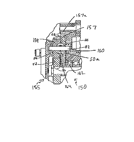
Figure 2 is a partial cross-sectional
illustration of linear actuator 150 incorporating the anti-
lockup feature of the present invention. Linear actuator
150, apart from the improved anti-lockup intermediate gear
train assembly 155 of my new design, otherwise corr~sponds
to linear actuator 10 (Figure 1) disclosed in the aforesaid
United States Patent 4,712,441. Identical reference
numerals are employed in Figures 1 and 2 to denote elements
common to both embodiments.
Anti-lockup gear train assembly 155 comprises a
first intermediate gear 157 and a second intermediate gear
159 mounted on dowel pin 82 journalled between bearing 84
and 86. The first intermediate gear 157 is spaced from
bearing 84 with spacer 160 and has gear teeth 157a for
contacting the drive pinion gear 48. The second
intermediate year 159 has gear teeth 159a for contact with
the main drive gear 52. A pair of dowel pins 162 are
press-fitted or otherwise fixed within blind holes 164
formed parallel to each other within second gear 159 on
opposite sides of dowel
~:
29536~
pin a2~ ~h~ ~r~a ~nd~ 16~. of dow~l pin~ 1~2 pro~e~ ~rom the
right-hand sid~ ~Figure 3) of ~e~ond ge~ g g~ner~lly
perpendlcul~r ~o th~ pl~ne o~ th~ ond g~ar whe~ th~y ar~
resp~ctively received wl~h ar~uate ~lots 165 formed in fi~st gear
. 157 in diametri~lly oppo~lng ~ela~n ~bout dowe~ pin 8~. The
diameters o~ dow~l plns 152 ~t ~ee ends 162a thexeof 18 sllgh~y
le~ th~ ~he radial width of ~aoh s~ot 16~ to p~ovide a loo
it therewlth. ThQ dowel pins 162 are fu~th~ dlmensioned so
tha~ ~ree ends 16~a pro~ect well within the slots ~i.e.,
preerab~y at least h~lf the thickness o~ ~h~ slo~ ~s ~ea~ured
between the parall~1 end ~aces o~ gear 1~7) without pro~ecting
outw~dly from the B10~ tow~ds bearing`84.
U~on aatuatlng d~ive motor 44 t~ operate linear
octuato~ lS~, th~ motlve forc~ transmit~ed ~hrough ou~put shaf~
lS ~2 drive~ pinlon 48 t~ lmpart rotational moven~nt to first
~n~rmediate gear 157. Initially, the first int~rmediate ~ear
157 is ln the po~ition general~ y depicted in ~igu~e 4 with dowel
~ins 162 ~ositioned mo~e or less against diametrically oppo~ed
ends o~ ~lots 16~. ~owev~r, rota~on ~ g~r 157 in th~ ~unter
.aloclcwlse dir~t~ on o~ Figure~ 4 caus0~ t~l~ dowel pins 162 to
travel th~ough the ~lots by vl~tue of the rot~ry movement of the
slo~8 ~ormed in the flrst intermediate~ gear. During this
intorv~ t wil~ be appre~iated that drive motor 44 i~ only
powerlng driv~ plnion 48 and ~he ln~e~mediatc gear 1S7 and
therefore e~counters mlnimal inertla as th~ moto~ ou~put ~aft
ro~a~es 'co opera~lng spe~d a~ which time dowel plns 1~ abu~
against ~hs opposi~e diame~rlcally opposed end~ ~f ar¢uats slots
1~5. When this occurs, drive motor 44 ha~ developed sufficien~
torqu~ to abruptly transm~t motiYe force ~o se~ond intermedlate
ge~r 15~ po~ering main drlve gear 52, drive scr~w S4, drive nu~
11
i, ,1
~ ~9 5
5~ and ~xten~ion rod 5~ to overcome the inertial r~ anc~ o~
these driven pa~s ~ dri~e thq ou~put l~ad. I~ th~ m~n~e~, the
103t motion arran~ment pro~i~e~ by arcuat~ slo~s 16~ and dowel
pin~ 162 1~ ~ea~s 157,159 respectively allow ~rive motor 44 to
develop opora~ing to~ue t~ re~ia~ly oper~t~ linear a~tu~tor 150
by eliminati ng the tenden~y of ~he driven parts to lockup with or
without an output loa~ eor3ne~ed ~h~!re~o.
~ he angular extent of ea~h 310t 165 in the
clrcumferen~ial dirqot~on of gear 157 is somewhat depen~ent upon
LO the gear ra'cio betweerl d~lve plnion 48 and first intermediate
gear 157. To explain, it requlres approximately one revolution
of output ~ha~ nd ther~by drive J?inion 4 ~plus or minu~
25% ) for the ou~p-~t ~;h~ft to reach operatiny ~pe~d and ths~eby
d~velop suf~ nt anti-~oakup tor~ue, Therefo~ is
L5 preferabl~s to design the arauate interval o~ ea~h ~lot 1~$ so
that drive pinion 48 ~ompl~e~ one r~volution before dowel pins
162 t~avel from on~ end of ~heir asso¢l~ted slot to the opposite
end. In on~ ~ommerci~l embodim~n~ o~ linea~ a~tuato~ 15G, the
gear ratio is pr~f~a~ly ab~ut 1:4, meanin~ that slots 165 ~hould
20 be formed to subtend an angular interv~l of approximately gO
degree~ ~or sach ~lo~. In the event the gear ratio changes as
b~tw~an di~ferent ~omme~c:ial ~mbodiments of lirle~r aetuato~ 150,
it i~ pre~e~abl~ to deslgn slots 1~5 in the m~nner deso~ ed
above so that pinion 43 compl~3t~ one ~volu~ion be~o~e dowel
25 p~ns 1~2 t~qvel i'rom one end o~ thei~ as~ooi.~t~d sJ~o~ to th~
opposite end.
It will b~ appr~iated that the for~e imp~c~ ~cting
upon second lnt~mediate gear 15~ as dowel~ 162 ~ach th~
op~?osite end o~ their assoclated ~lot~ 1~5 i9 to some d~gree
30 dependen~ upon th~ radial posltion o tha ~310t:5 relativ~ t~o the
1~
2~ 5 361
central lon~i~udin~l axi8 o$ dowel pin ~2 upon whiah gears
157,l5g ~re mounted. In o~her wo~d~, by lo~atln~ ~lots 1~5 at a
greater radlal d~stanee ro~ dowel p~n ~, the ~ora~ or ~hammer
blow" imp~t transmitt~d from gear 157 to the ge~r 159 is ~reater
. than i~ slots 16~ wer~ lo~ed close~ to dowel pin 82. In oth~r
words, by loc~tlng thq s~ot# 165 ~t ~ greater ~adial looation
than th~t di~clo~ed in Figure ~, it would not be neces~ary for
~lot~ 165 ~o have an ar~uate qxtent dependent upon th~ gear
~atio; i.e., the ~ame impact ~ox¢e ob~ained with the arrangement
o ~lots depicted ~n ~ig~r~ 4 ~n al~o be obtained by ~ ocatin~
the ~lots at a radially ~reate~ po~ition th~n the ~igure 4
lo~ation and, lf deslred, ~orming the ~lots to have an arauate
extent less than 50 degree~. In commercial.praatice o~ linear
ac~uator 150, ho~ever, it is often dlfflault to relocate slots
lS 1~5 from the F$gu~e ~ position due to the smaller diam~ter o~
~e~ond lntermcd~a~ gear l5g whl¢h typia~lly msy have a root
diameter of a.~ inch~s ~one lnch out~ide diameter) whereas dowel
p~n 82 ha~ a t~plcal diameter ~ 3/8 inches. It ls preferred,
howeve~, to maint~in slots l~ ~nd thereby dowel pln~ 1~2 midw~y
betw~en th~ ou~er periph~ry o~ dowel pin 82 Qnd the root di~meter
of s~cond ~.nterme~iate gear 15~.
Althou~h the present in~en~ion may be pra~ic~d with
onl~ on~ ~lot 165 ~ceivln~ e end 162a oP ~ne dowel pin 162,
~h~ p~ovislon of two slots 15 preferred to provide better forcs
di~ribution to prevent shearing of the dow~l pin~ 162.
The in~ention may be embodied in other specific for~s
without dep~rting from the splrit or e~sentia~ char2cteristi~s
thereof. For example, lt i~ possibl~ ~o for~ arcuate slot~ 165
in ~e~ond intermediate gear lss and to p~es~ fit dowels 162 in~o
holes formed in first gear 1~7 with ~ree ends 162a pro~e~ting
13
~ . .
12953~1
lnto the ~econd g~ar. ~he p~e8en~ embodim~nts are ther~fore to
be co~side~ed in all resp~cts a~ illu~t~tive ~nd not ~s
restric~ , the 6aope of the invention being i~dicated by th~
appended claims rathe~ than by the foregoing description, ~nd all
changes whloh come withln the meaning and ~ange of e~uivalency of
tho claim~ are the~efore intended ~o be ~-mbraced ~herein.