Sélection de la langue

Search

Sommaire du brevet 1296050 

Énoncé de désistement de responsabilité concernant l'information provenant de tiers

Une partie des informations de ce site Web a été fournie par des sources externes. Le gouvernement du Canada n'assume aucune responsabilité concernant la précision, l'actualité ou la fiabilité des informations fournies par les sources externes. Les utilisateurs qui désirent employer cette information devraient consulter directement la source des informations. Le contenu fourni par les sources externes n'est pas assujetti aux exigences sur les langues officielles, la protection des renseignements personnels et l'accessibilité.

Disponibilité de l'Abrégé et des Revendications

L'apparition de différences dans le texte et l'image des Revendications et de l'Abrégé dépend du moment auquel le document est publié. Les textes des Revendications et de l'Abrégé sont affichés :

  • lorsque la demande peut être examinée par le public;
  • lorsque le brevet est émis (délivrance).
(12) Brevet: (11) CA 1296050
(21) Numéro de la demande: 1296050
(54) Titre français: DISPOSITIF D'EVAPORATION CATHODIQUE
(54) Titre anglais: CATHODE EVAPORATING DEVICE
Statut: Périmé et au-delà du délai pour l’annulation
Données bibliographiques
(51) Classification internationale des brevets (CIB):
  • C23C 14/32 (2006.01)
(72) Inventeurs :
  • VELTROP, HANS
  • WESEMEYER, HARALD (Allemagne)
  • BUIL, BOUDEWIJN JOHANNES ATHANASIUS MARIA
(73) Titulaires :
  • HAUZER HOLDING B.V.
(71) Demandeurs :
  • HAUZER HOLDING B.V.
(74) Agent: MARKS & CLERK
(74) Co-agent:
(45) Délivré: 1992-02-18
(22) Date de dépôt: 1988-03-14
Licence disponible: S.O.
Cédé au domaine public: S.O.
(25) Langue des documents déposés: Anglais

Traité de coopération en matière de brevets (PCT): Non

(30) Données de priorité de la demande:
Numéro de la demande Pays / territoire Date
8700620 (Pays-Bas (Royaume des)) 1987-03-16

Abrégés

Abrégé anglais


Abstract
Cathode arc discharge evaporating device having a body of revolution ascathode. The target surface is arranged at the outside surface of the
body of revolution. To control movement of the arc spot a magnetic
field generating device is provided inside the body of revolution,
which may be moveable with respect to the cathode.

Revendications

Note : Les revendications sont présentées dans la langue officielle dans laquelle elles ont été soumises.


THE EMBODIMENTS OF THE INVENTION IN WHICH AN EXCLUSIVE
PROPERTY OR PRIVILEGE IS CLAIMED ARE DEFINED AS FOLLOWS:
1. Cathode arc evaporating device, comprising an
evaporation surface of a material to be evaporated
formed as a surface of a hollow body of revolution,
means for supporting said evaporation surface for
rotation about an axis, and at least one arc spot
steering magnetic field generating device supported
within said evaporation surface for movement in a
direction parallel to the axis of rotation of said
evaporation surface for avoiding non-uniform erosion of
said evaporation surface.
2. Device according to claim 1, wherein the magnetic
field generating device comprises an assembly of
permanent magnets.
3. Device according to claim 1, wherein the magnetic
field generating device comprises an assembly of electro
magnets.
4. Device according to claim 1, wherein dark screen
means are provided on one side of the evaporation
surface.
S. Device according to claim 1, wherein means are
provided to translate the body of revolution with regard
to the magnetic field generating device.
6. Device according to claim 1, wherein the magnetic
field generating device is rotatable in a plane
substantially perpendicular to the rotational axis of
the body of revolution.
- 6 -

Description

Note : Les descriptions sont présentées dans la langue officielle dans laquelle elles ont été soumises.

5~
--1
Cathode Evaporating Device
The present invention relates to a cathode arc
discharge evaporating device, comprising a target surface
of the material to be evaporated, embodied as a surface of
a hollow body of revolution and provided with at least one
arc controlling magnetic field generating device.
Such a device is known from GB-A-2127043. In this
specification a cylindrical consumable cathode surface
from which the material to be deposited is migrated is
described in which a work piece is introduced. The housing
of this device is connected as anode. Around the housing of
this device a magnetic coil is provided. This coil
primarily functions to control the flow of material from
the target surface to the substrate. However, it also has
some effect on the position of the spot of the arc drawn
between anode and cathode on the target surface.
Controlling of the position of this spot is very important
because it is generally desired to consume the target
surface as evenly as possible. To realise this object, it
is necessary that the arc spot runs along a defined path
along the target surface and that each point of that target
surface is touched the same number of times by the arc
spot. Because the distance of the magnetic field generating
device according to this British specification to the
target surface is quite considerable it is not possible to
obtain precise controlling of the path of the arc on the
target surface. From this description it is also clear that
it is not the objection to do so.
. ~ " ~ ~

~36
-la-
The invention aims to obviate these drawbacks and
to obtain a cathode surface without an erosion relief
that has tranches or canyonsO This object is realized
in that said magnetic field generating device is
provided internally of the body of revolution and in
that the outer surface of the body of ravolution
comprises the evaporation surface. By introducing the
magnetic field generating device inside of the body of
revolution, constituting the evaporation surface, it is
possible to obtain a precisely controlled movement of
the arc spot along the evaporation surface. This
because the distance from the magnetic field generating
device and the arc spot is considerably reduced with
regard to the device according to the British
specification.
Thus, an aspect of this invention is as follows:
Cathode arc evaporating device, comprising an
evaporation surface of a material to be evaporated
formed as a surface of a hollow body of revolution,
means for supporting said evaporation surface for
rotation about an axis, and at least one arc spot
steering magnetic field generating device supported
within said evaporation surface for movement in a
direction parallel to the axis of rotation of said
evaporation surface for avoiding non-uniform erosion of
said evaporation surface.
This magnetic field generating device can comprise
an assembly of permanent magnets as well as an assembly
o~ electro magnets or its combination.

If it is intended that the spot is only within a restricted
area of the evaporation surface, screen means can be provided. By
moving the body of revolution with regard to the screen means it is
possible to provide a fresh target surface. This embodiment is impor-
tant if the work piece only extends on one side of the body ofrevolution.
According to a further preferred embodiment means are pro-
vided to rotate the body of revolution with respect to the magnetic
field generating device and/or screen means. By this a target surface
]0 can be evenly used.
It is of course also possible to translate the body of revol-
ution with respect to the magnetic field generating device and/or
screen means. Combinations of both rotational and translational move-
ment are also envisaged by this invention.
]5 It is also possible to rotate the magnetic field generating
device substantially perpendicular to the axis of the body of revol-
ution. If this magnetic field generating device is an electro magnetic
coil, rotating has to be understood in an electromagnetic sense. The
expression "with respect to" has to be understood as that it is
possible to move either one or the other component, the other or one
component respectively being fixed or that both components move in the
same sense with a different speed or in a different sense with the same
or different speed.
The invention will be further elucidated by way of example
with reference to the accompanying drawings, in which
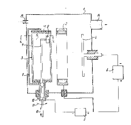
Figure 1 is a partially cross-sectioned side elevation of the
device according to the invention,
Figure 2 is a cross-section according to 2-2 in fig. I of the
cathode arrangement according to figure ],
Figure 3 is a side elevation of a cathode arrangement which
can be used in a device according to figure 1,
Figure 4a and 4b are an exploded elevational view and a
cross-sectional view according to IVb-IVb respectively of the arrange-
ment of a hollow cylinder in which a magnetic field generating device
is introduced,
Figure 5 is in projection the path of movement oE the arc at
a stationary magnetic field generating device and

~296~
3--
Figure 6 is a further embodiment of a magnetic field gener-
ating device arranged in a hollow cylinder as cathode.
In figure I a cathode/anode arc discharge device is shown
comprising a housing l in which an anode ring 2 and cathode cylinder 3
5 are provided. The anode ring 2 can be cooled by means known as such in
the art. Furthermore a substrate holder 4 is provided. Anode ring 2 and
cathode cylinder 3 are connected to arc dc supply 5. The voltage of
substrate holder 4 is kept between 0 and some negative K volts by high
voltage supply 6. Cathode cylinder 3 is partially surrounded by insul-
10 ation 41 and double dark screen shielding 7. This is also clear fromfigure 2. In cathode cylinder 3 a magnetic field generating device 8 is
provided suspended to a rod 9. As is schematically shown by arrow 10
rod 9 can be moved up and down by means not shown. With arrow ]] it is
indicated that it can also rotate. From arrow 12 it is clear that
]5 cathode cylinder 3 can be rotated by means not shown but being known in
the art. Housing ] is provided with an inlet 13 for introducing of gas
and an outlet 14 to which a pump not shown can be connected to evacuate
housing l.
The device according to figure I functions as follows. When
20 arc supply 5 is switched on an arc is ignited and maintained between
anode ring 2 and cathode cylinder 3. At the spot where this arc touches
cathode cylinder 3 the cathode material from which the cathode cylinder
3 is made migrates a flow of atoms, and ions to substrate holder 4. By
imposing a negative voltage to substrate holder 4 an optimised depos-
25 ition of this material is obtained. Normally the cathode spot will tra-
vel randomly over the cathode cylinder. This means that from the
cathode surface, macro particles and droplets will be emitted and an
uneven erosion will happen. To prevent this, magnetic field generating
device 8 is provided. The cathode spot will be attracted to and con-
30 trolled by the magnetic field generated by this device 8. To evenlyconsume the cathode cylinder 3 it is possible to move magnetic field
generating device 8 by rod 9 relative to cathode cylinder 3 as indic-
ated by arrows 10. It is also possible to rotate rod 9 by which magn-
etic field generating device is moved along the surface of the cathode
35 cylinder 3. This is also shown in fig. 4a and 4b. If one wishes the
cathode arc spot will only travel on that side of the cathode which
faces the substrate, so that cathode material evaporates in the
, .. .

6~
--4--
direction of substrate holder, a double dark room shielding is pro-
vided. By this the spot will only move along the exposed surface of
cathode cylinder 3. To evenly consume cathode cylinder 3 in this case
cylinder 3 can be rotated as indicated by arrow ]2. During operation of
the device housing ] is evacuated by discharging of gasses through out-
let 14. During igniting of the arc gass can be supplied through inlet
]3.
In fig. 3 another embodiment of the cathode cylinder indic-
ated as 16 is shown. In this embodiment as means for preventing the arc
to wander from the cathode surface two rings of ceramic insulation ]5
are provided. In figure 3 also the arc spot trajectory ]7 is indicated
which will be followed if cathode cylinder 3 and magnetic field gener-
ating device 8 as shown in fig. 1 are fixed relative to each other. To
prevent localized erosion during operation of the device cathode ]6 and
]5 magnetic field generating device 18 are moved with respect to each
other as indicated by arrows in figure 3. In figure 4b a cross-section
of the cathodic cylinder 3 according to fig. ] is shown having a speci-
fic embodiment of the magnetic field generating device in these figures
indicated with 18. Device 18 comprises a permanent magnet assembly
having a central pole 23 surrounded by a soft iron magnetic conductor
portions 25 and 24 with opposite polarity to pole 23.
Although in this embodiment magnetic field generating device
is a permanent magnet assembly the magnetic field generating device
according to figure 1 can also comprise a coil assembly in which case
through rod 9, supply electrical leads have to be provided. It is also
possible to rotate this magnetic field generating device around access
19 as shown in figure 1 by mechanical and/or electrical Means known in
the art.
Fig. 5 shows the projection of the surface of the cathodic
cylinder 3. The arc trajectory is referred to with 27. To obtain this
trajectory a magnetic field generating assembly as shown in fig. 4a can
be used having an elongated shape. To obtain trajectory 27 the magnetic
: field generating device can be fixed with regard to the cathode cylin-
der. When the cathode cylinder is rotated with regard to the magnetic
field generating device the vertical portion of trajectory 27 will con-
stantly change whilst the upper and lower portions of this trajectory
in fig. 5 indicated with 28 remain the same. To prevent erosion near 28

~ 2~6~
the speed of movement of the arc has to be increased. The speed of the
arc spot with respect to the cathode cylinder can be described as the
sinusoidal function. In addition to that an electrical modulDtion by
means of coils can be supplied to hte arc track to avoid erosion at
places like 28.
In fig. 6 a further embodiment is shown in which the magnetic
field generating device 32 comprises an assembly of permanent magnets
39. Between these magnets 39 soft iron parts 40 are provided. Device 32
can be moved upward and downward by rod 9 with respect to cathode 3. In
~0 this amendiment the arc spot will be at those points in which the com-
ponents of the magnetic field perpendicular to the cathode surface are
zero and where the parallel components are at maximum.
In this embodiment it is not necessary to rotate rod 9 be-
cause the arc spot rotates on the lateral surface of the cathode. A
~5 helical path of the arc trajectory is obtained when rod 9 is moved.
Although preference is given to the embodiments described, it
has to be understood that many modifications are possible. When using
electro magnetic coils as magnetic field generating device it is
possible to provide a modulating magnetic field. Furthermore it is
possible to use all magnetic field generating devices known in the
prior art.

Dessin représentatif
Une figure unique qui représente un dessin illustrant l'invention.
États administratifs

2024-08-01 : Dans le cadre de la transition vers les Brevets de nouvelle génération (BNG), la base de données sur les brevets canadiens (BDBC) contient désormais un Historique d'événement plus détaillé, qui reproduit le Journal des événements de notre nouvelle solution interne.

Veuillez noter que les événements débutant par « Inactive : » se réfèrent à des événements qui ne sont plus utilisés dans notre nouvelle solution interne.

Pour une meilleure compréhension de l'état de la demande ou brevet qui figure sur cette page, la rubrique Mise en garde , et les descriptions de Brevet , Historique d'événement , Taxes périodiques et Historique des paiements devraient être consultées.

Historique d'événement

Description Date
Inactive : Demande ad hoc documentée 1997-02-18
Le délai pour l'annulation est expiré 1996-08-18
Lettre envoyée 1996-02-19
Accordé par délivrance 1992-02-18

Historique d'abandonnement

Il n'y a pas d'historique d'abandonnement

Titulaires au dossier

Les titulaires actuels et antérieures au dossier sont affichés en ordre alphabétique.

Titulaires actuels au dossier
HAUZER HOLDING B.V.
Titulaires antérieures au dossier
BOUDEWIJN JOHANNES ATHANASIUS MARIA BUIL
HANS VELTROP
HARALD WESEMEYER
Les propriétaires antérieurs qui ne figurent pas dans la liste des « Propriétaires au dossier » apparaîtront dans d'autres documents au dossier.
Documents

Pour visionner les fichiers sélectionnés, entrer le code reCAPTCHA :


Pour visualiser une image, cliquer sur un lien dans la colonne description du document (Temporairement non-disponible). Pour télécharger l'image (les images), cliquer l'une ou plusieurs cases à cocher dans la première colonne et ensuite cliquer sur le bouton "Télécharger sélection en format PDF (archive Zip)" ou le bouton "Télécharger sélection (en un fichier PDF fusionné)".

Liste des documents de brevet publiés et non publiés sur la BDBC .

Si vous avez des difficultés à accéder au contenu, veuillez communiquer avec le Centre de services à la clientèle au 1-866-997-1936, ou envoyer un courriel au Centre de service à la clientèle de l'OPIC.

({010=Tous les documents, 020=Au moment du dépôt, 030=Au moment de la mise à la disponibilité du public, 040=À la délivrance, 050=Examen, 060=Correspondance reçue, 070=Divers, 080=Correspondance envoyée, 090=Paiement})


Description du
Document 
Date
(aaaa-mm-jj) 
Nombre de pages   Taille de l'image (Ko) 
Abrégé 1993-10-26 1 19
Revendications 1993-10-26 1 32
Dessins 1993-10-26 3 53
Description 1993-10-26 6 218
Dessin représentatif 2000-08-23 1 15
Taxes 1994-01-11 1 26
Taxes 1995-01-17 1 37