Note : Les descriptions sont présentées dans la langue officielle dans laquelle elles ont été soumises.
~Z96;Z27
POWER BURNER-FIRED CONDENSING MODE FURNACE
BACKGROUND OF THE INVENTION
Field of the_Invention
This invention relates generally to gun-type, power fluid
fuel burner-fired hot air furnaces, and more particularly to a
condensing mode furnace of that type.
Description of the Prior Art
Gun-type, power fluid fuel burner~fired hot air furnaces
conventionally comprise a gun-type power burner, such as an oil
or gas burner; a heat exchanger for extracting heat from the
products of combustion of the burner and having a cornbustion
~15 chamber therein which communicates with the heat exchanger and
into which the burner fires; an exhaust passage for carrying the
products of combustion from the heat exchanger to an exhaust
flue, an air passage for carrying a flow of air over the heat
exchanger to a hot air outlet thereby to extract heat from the
heat exchanger; and a blower for causing a flow of air through
the air passage.
Condensing mode furnaces are known which include a condenser
for condensing water out of the products of combustion to reduce
~the stack temperature and thereby increase the efficiency of the
furnace.
Conventional gun-type, power fluid fuel burner-type furnace
systems typically include a thermostat for sensing the tempera-
ture in the space to be heated, and a furnace control including a
fan and limit switch. Closing of the thermostat contacts initi-
ates operation of the burner followed by initiation of operation
of the blower by the fan switch. Opening of the therrnostat
- 1 - ~
~9~f~27
contacts terminates operation of the burner and the f~n switch
thereafter -terminates operation of the blower.
SUMMARY OF TIIE INVENTION
The invention, in its broader aspects is embodied in a hot
air furnace including a gun-type power fluid fuel burner, hea~
exchanger means for extracting heat from the products of com-
bustion of the burner, exhaust passage means for carrying ~he
products of combustion from the heat exchanger means to an
exhaust flue~ air passage means for carrying a flow of air over
the heat exchanger means thereby to remove heat therefrom, and
air moving means for causing a flow of air through the air
passage means. In accordance with the invention, condenser means
is provided in the exhaust passage means for removing water from
the products of combustion therein, the condenser means being
exposed to the air passage means. Drain means is provided
connected to the exhaust passage means for removing condensate
therefrom, and second air moving means is provided in the exhaust
passage means for causing an air flow therein from the heat
exchanger means to the exhaust flue.
In the preferred embodiment of the invention, the condenser
means is a fin and tube-type condenser serially coupled between
the heat exchanger having a combustion chamber therein into which
the burner fires, and a ~ent having the second air moving means
in the form of a blower therein.
It is accordingly an object of the invention to provide an
improved gun-type power fluid fuel burner-fired hot air furnace.
Another object of the invention is to provide an improved
gun-type power fluid fuel burner-fired hot air furnace including
a condenser for removing water from the products of combustion.
3n The above-mentioned and other features and objects of this
invention and the manner of attaining them will become more
r 1L ~ i Z ;~7
apparent and the invention itself will be best understGod by
reference to the following description of embodiments of the
invention taken in conjunstion with the accompanying drawings.
BRIEF ~ESCRIPTION OF THE DRAWINGS
Fig. 1 is a side elevational view of the improved yun-type,
power fluid fuel burner-fired, condensing mode hot air furnace of
the invention;
Fig. 2 is a top view, partly in cross-section and partly
broken away, showing the furnace of Fig. 1 with the top panel of
the furnace enclosure removed;
Fig. 3 is a cross-sectional view taken generally along the
line 3-3 of Fig. 2;
Fig. 4 is a cross-sectional view taken generally along the
line 4-4 of Fig. 3;
Fig. 5 is a fragmentary cross-sectional view showing the
connection of the condensate drain line to the exhaust vent of
the furnace of the invention;
Fig. 6 is a fragmentary cross-sectional view illustrating a
modification of the invention;
Fig. 7 is a cross-sectional view taken generally along the
line 7-7 of Fig. 6 and
Fig. 8 is a schematic diagram showing the control system for
the furnace of the invention.
BRIEF DESCRIPTION OF THE PREFERRED EMBODIMENT
~ .. ._ . ..... _ __ . ._ . _ .
Referring now to Figs. 1 through 5 of the drawings, there is
shown the improved gun-type, power fluid fuel burner-fired,
condensing mode furnace of the invention, generally indicated at
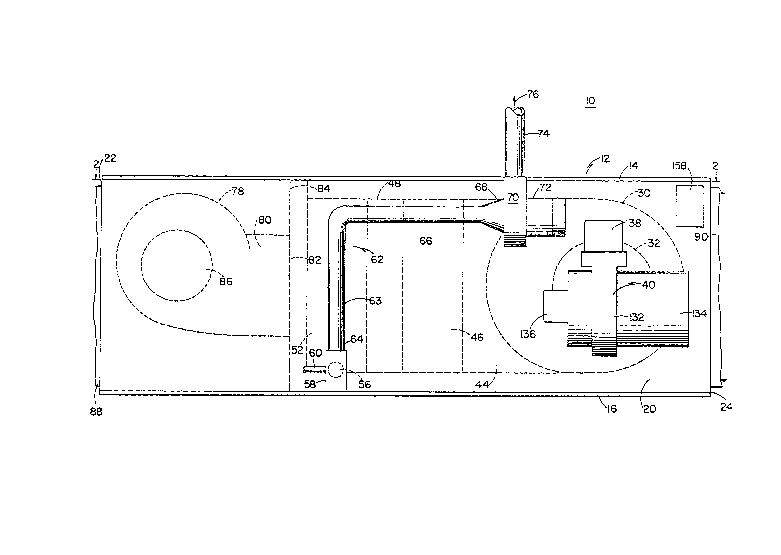
10. Furnace 10 has enclosure or casing 12 formed by top and
bottom walls 14, 16, side walls 18, 20 and end walls 22, 24. End
wall 22 has cold air inlet opening 26 therein and end wall 24 has
a hot air outlet opening 28 therein.
-- 3 --
3L29~
Heat exchanger 30 formed of suitable metal is supported
within casing 12 by a suitable support means (not sho~7n) adjacent
but spaced from end wall 24, and spaced from top and bottom walls
14, 16 and slde walls 18, 20. Combustion chamber 32, formed of
suitable material, is positioned within heat exchanger 30 and has
opening 34 in its side wall communicating with the interior of
heat exchanger 30.
Combustion chamber 32 has sleeve 36 extending outwardly to
casing side wall 20 and terminating at flange 38. Conventional
gun-type, power fluid fuel burner 40 is mounted on flange 38 in
conventional fashion and has its blast tube 42 extending through
sleeve 36 lnto the interior of combustion chamber 32 so that
burner 40 fires into combustion chamber 32. Burner 40 may be
either a power oil burner or a power gas burner and in a specific
embodiment of the invention, burner 40 may be a model HS oil
burner manufactured by the assignee of the present application.
Heat exchanger 30 preferably has a generally oval cross-sectional
configuration as best seen in Figs. 1 and 3.
Duct 44 is connected to heat exchanger ~0 and communicates
therewith. Primary fin-and-tube condenser assembly 46 extends
transversely in casing 12 between duct 44 and manifold 48, end
portion 50 of duct 44 also serving as a manifold for the tubes oi
condenser assembly 46. Secondary fin-and-tube condenser assembly
52 extends transversely between manifold 48 and manifold 54 in
spaced, parallel relationship with conde~ser assembly 46. Vent
duct section 56 extends outwardly from manifold 54 through casing
side wall 20 adjacent bottom wall 16 to sump 58. Condensate
drain line 60 is connected to sump 58 as will hereinafter be more
fully described.
Another vent duct 62 is provided having generally upwardly
extending section 63 with its lower extremity 64 connected to
6~
sump 58, and horizontal section 66 -terminating in inlet Ç~ of
blower 70 driven by motor 72. ~xhaust flue 74 is connected to
the discharge of purge blower 70.
It will now be seen that duct 44, tubes lOD of cond~nser
assembly 46, manifold 48, tubes 102 of condenser assembly 52,
manifold 54, vent duct section 56, sump 58, and vent duct 62 form
an exhaust passage for carrying the products of combustion from
burner 40, combustion chamber 32 and heat exchanger 30 to exhaust
flue 74 as shown by arrows 76 in Figs. 1, 2, 3 and 4, the
products of combustion being caused to flow through the exhaust
passage by purge blower 70.
Conventional furnace blower 78 has its air discharge 80
communicating with condenser assemblies 46, 52 and heat exchanger
30 through opening 82 in partition 84 extending transversely
across casing 12, Cool air enters inlet openings 86 in blower 78
through cool air inlet opening 26 i.n end wall 22 to which cool
air inlet duct 88 may be connected. Hot air duct 90 may be
connected to hot air discharg.e opening 28 in end wall 24 of
casing 12. It will be understood that cool air inlet opening 26
need not be located in end wall 22.
It will now be seen that top and bottom walls 14, 16, and
side walls 18, 20 of casing 16 form air passage g2 extending
between opening 82 in partition 84 and hot air discharge opening
28 in end wall 24, air passage 9Z surrounding condenser
assemblies 46, 52 and heat exchanger 30. Thus, cold air drawn
into blower 78 through cold air inlet opening 26 and cold air
duct 88, as shown by arrows 94, is caused to flow over condenser
assemblies 46, 52 and heat exchanger 30 to extract heat
therefrom, as shown by arrows 96, and finally the thus-heated air
i5 caused to flow through hot air discharge opening 2B and duct
90, as shown by arrows 98.
Referring now particularly to Figs. 3 and 4, condenser
assemblies 46, 52 respectively comprise a plurality of
thin-walled tubes or conduits 100, 102 each having opposite open
ends 104, 106 and 108, 110, respectively. Tubes 100 of condenser
assembly 46 extend transversely between manifold portion S0 of
duct 44 and manifold 48 with their cpen ends 104, 106
respectively communicating therewith, tubes 100 being in spaced,
parallel relation. Tubes 102 of condenser ass~mbly 52 extend
transversely between manifold 48 and manifold 54 with their open
ends 108, llQ respectively communicating therewith, tubes 102
being in spaced, parallel relationship. Thus, the products or
combustion flow serially from duct 44 through parallel tubes 100
comprising condenser assembly 46, through manifold 48, through
the parallel tubes 102 to manifold 54 and vent duct 56, as shown
by arrows 76 in Fig. 4. Tubes 100, 102 of co~denser assemblies
46, 52 extend through thin-walled fins 112, 114 in conventional
fashion (Fig. 2). In a specific embodiment of the invention,
condenser assemblies 46, 52 respectively comprise fifteen
stainless steel tubes each one inch in diameter and twelve inches
long with eight to ten aluminum fins 112, 114 per inch. It will
be seen that the cool air from blower 78 flowing over and around
condenser asse~blies 46, 52, as shown by arrows 96, condenses the
water from the products of combustion, the resulting condensate
flowing through vent duct 56 into sump 58.
Referring now to Fig. 5, sump 58 comprises sleeve 116 with
its upper end 118 having a slip-fit with the lower extremity 64
of vent duct section 63. Vent duct section 56 is connected to
sleeve 116 lower end 120 of sleeve 116 has a slip-fit with sleeve
121 closed by cap 122. Because of the low stack temperatures
provided by the improved fuxnace of the invention, which may be
~Z~
less than 100F, sleeves 116, 121, cap 122, vent duct 62, and
exhaust flue 74 may be formed of PVC.
Dxain llne 60 has elbow 124 connected to its end 126 and
extending through the wall. of sleeve 116. Drain line 60 is
preferably is located below exhaust duct 56, as shown in Fig. 5.
Short extension 128 of drain line 60 is connected to elbow 124
and extends downwardly into sleeve 121. It will be seen that
when condensate drained from condenser assemblies 46, 52 through
exhaust duct 56 rises in sump 58 to the level shown by dashed
: line 130, the condensate will be drained-away by drain line 60.
Burner 40 includes conventional blower 132 driven by motor
134, conventional oil pump and valve assembly 136, and conven-
tional ignition transformer 138. Blower 132 provides combustion
and secondary air flow in blast tube 42, and provides a higher
pressure than that provided by purge blower 70 in the exhaust
passage. Thus, when operation of burner 40 is initiated, as will
hereinafter be more fully described, the pressure in the exhaust
passage including vent duct 56, as described above, provided.by
blower 132 causes the condensate level in sump 58 to drop and
forces any condensate in which drain line extension 128 is
submerged outwardly through extension 128, el~ow 124 and drain
line 60. After start of operation of burner 40 and blower 132,
the pressure is equalized and thus, the pressure in the exhaust
passage and exhaust duct 56 returns to the lower level provided
! by blower 70 and the condensate level rises zgain in sump 58, any
. condensate rising above level 130 being drained through drain
line 60.
Referring now to Figs. 6 and 7, primary condenser assembly
46 ~Fig. 2) may be replaced by secondary heat exchanger 140 so
that all of the condensing function i~ performed by secondary
condenser assembly 52. Secondary heat exchanger 140 comprises a
~2~ 7
plurality of conduits or tubes 142 respectively having open ends
144, 146 which respectively communicate with manifold end portion
50 of duct 44 and manifold 48, as shown. In a specific
embodiment, five tubes 142 were provided formed of thin-~7all
aluminized steel each twelve inches long and five inches by two
inches in cross~section.
Each tube 142 of secondary heat exchanger 140 has baffle
assembly 148 therein. Each ~affle assembly 148 comprises a
plurality of oppositely extending baffle elements 150, 152
secured to elongated suppoxt members 154. Baffle elements 150,
152 cause the products of combustion to flow in an undulating or
serpentine path through tubes 142, as shown by arrows 155,
thereby to wipe the interior surfaces of tubes 142 for more
efficient heat transfer. In a specific embodiment, about ten
baffles 150, 152 were positioned in each tube 142.
Reerring now to Fig. ~, there is shown control system 153
for furnace 10. Control system 153 is adapted to be connected to
conventional thermostat 156 for sensing the temperature in the
space to be heated. Furnace 10 includes conventional fan and
limit switch 158 having thermostatically actuated fan switch 160
and thermostatically actuated limit switch 162. Fan switch 160
has its contacts closed in response to the temperature of the
heated air in air passage 92 adjacent hot air discharge opening
28 rlsing to a predetermined level, and its contacts opened when
that temperature falls below the predetermined level. Limit
switch 162 has its contacts opened when the temperature in air
passage 92 adjacent hot air discharge opening 24 rises above a
predetermined higher level.
Control system 153 comprises conventional furnace relay 164
including step-down transformer 166 having its primary winding
167 coupled across line voltage terminals 168 for reducing the
~ 2 ~ ~ ~2 ~
line volta~e, typically 120 volts, 60 Hertz, ~o a lower control
voltage acro~s its secondary winding 170, typically 24 volts.
The contacts of thermostat 156 couple secondary winding 170
of transformer 166 across operating coil 172 of relay 174 for
energization thereby. Relay 174 has normally open contacts 176,
178 and normally closed contacts 180. In a specific embodiment
of the invention, furnace relay 164 is a Honeywell R8239A relay.
Furnace blower 86 is operated by motor 182 connected by lead 184
to grounded side 186 of line voltage so~rce 168 and connected by
lead 188, le~d 190, fan switch 160 and lead 192 to ~'hot" side 194
of line voltage source 168.
Purge blower motor 72 is coupled by lead 196 and normally
open contacts 178 of relay 174 to side 194 of line voltage source
168, and is coupled by lead 198 to grounded side 186. Purg~
motor blower lead 196 is also coupled to side 194 of line voltase
suxface 168 by normally closed contacts 180 of relay 174, lead
190, limit switch 162 and lead 192.
Primary burner contxol 200 compxises step-down transformer
202 having its primary winding tool 204 coupled acros line
voltaye source 168 ~y normally open contacts 176 of relay 174,
and by lead 208, Purge blower motor 72 has centrifical switch
contacts 210 coupling secondary winding 212 of transformer 202
across operating coil 214 of primary control relay 216. Normally
open contac~s 218 of primary control relay 216 couple lead 206
which is coupled ~o side 194 of line voltage source 168 by
normally open contact 176 of relay 174, through limit switch 162
to lead 220. 1ead 220 is connected to one side of primary
winding 222 of ignition transformer 138, one side of burner motor
134, and one side of oil valve 136 thxough conventional time
delay 139. The other sides of primary winding 222 of ignition
transformer 138, burner motor 134 and oil valve 136 are coupled
_ 9 _
~ 2~227
to the grounded side 186 of line voltage source 168 by lead 208.
Conventional flame detector 224, after a predetermined number of
unsuccessful attempts to detect flame from burner 40 in
combustion chamber 32, latches-out normally closed con~acts 226
in series with contacts 218 of primary control relay 216. The
voltage across secondary winding 212 of transformer 202 typically
is 24 volts. In a specific embodiment, primary control 200 is
r~
Honeywell R8184K1006.
In operation, when the contacts of thermostat 156 close thus
calling for heat, operating coil 172 of furnace relay 174 is
energized thus closing contacts 176, 178. Closing of furnace
relay contacts 178 energizes purge blower motor 72 thereby to
initiate operation of purge blower 70 to prepurge any unburned
gases in combustion chamber 32 and heat exchanger 30. When purge
blower motor 72 reaches the predetermined speed, centrifical
switch contacts 210 are closed thus energizing operating coil 214
of primary control relay 216 closing its contacts 218. ~imit
switch 162 is normally closed and thus, closure of relay contacts
218 enexgizes burner motor 134, ignition transformer 138, and oil
~ valve 136 after a short time delay provided by time delay 139,
all in conventional fashion. Assuming that satisfactory ignition
of the burner has been obtained and thus that flame detector 224
has not latch-opened its contacts 226, when a prede~ermined
temperature is reached in air passage 92 adjacent hot air
discharge opening 24, fan switch 160 closes thus energizing
furnace blower motor 182 by lines 188, 190, 192, 194, and 184,
186. It will be observed that purge blower motor 72 remains
energized to operate purge blower 70 during operation of burnex
40 through contacts 178 of furnace relay 174 which i~ energized
while the contacts of thermostat 156 are closed.
` ~!L2~2~7
When thermostat 156 is satisfied thus opening its contacts,
operating coil 172 of furnace relay 174 is deenergized thus
opening its contacts 176, 178 and closing its contacts 180.
Opening of furnace relay contacts 176 deenergizes primary winding
204 of primary control trans~ormer 202 thus deenergizing
operati~ coi~ 2~4 o~ prin~ary contro~ relay ~6 o~eni~ its
contacts 218 and deenergizing ignition transformer 138, burner
motor 134 and oil valve 136.
Upon opening of the contacts of thermostat 156 when the
temperature is satisfied, contacts 180 of furnace relay 174 close
and thus purge blower motor 72 remains energized through lead
192, fan switch 160, lead 190 and leads 196, 198 thereby to
provide post-purge of any unburned gases remaining in combustion
chamber 32 and heat exchanger 30. When the temperature in air
passage 92 adjacent hot air discharge opening 24 falls to the
predetermined level, fan switch contacts 160 open thereby
deenergizing purge blower motor 72 and furnace blower motor 182.
Limit switch contacts 162 of fan and limit switch lS8 open at a
predetermined high temperature to protect against excessive
temperature in air passage 92 adjacent hot air discharge opening
24.
While a conventional gun-type power~ oil burner has been
described in connection with Fig. 8 of the drawin~s, such as
model HS manufactured by the assignee of the present application,
a conventional gun-type pressure gas burner, such as model HSG
also manufactured by the assignee of the present application, may
be substituted therefor. It will readily be understood that a
solid state control may be employed in place of the relay-type
control system shown in Fig~ 8 and described above.
It will now be seen that the invention provides an improved,
highly efficient gun-type pxessure fluid fuel burner-fired
- ~962~
condensing mode hot air furnace which, by reason of the ~ery low
stack temperatures provided, pexmits use of a small, lo~"
tempe.rature flue and thus elimination of the usual, costly high
-temperature 1ue pipes and chimneys with the attended risk of
fire.
While there have been described above the principles of this
invention in connection with specific apparatus, it is to be
clearly understood that this description is made only by way of
example and not as a limitation to the scope of the invention.
- ..
- 12 -