Sélection de la langue

Search

Sommaire du brevet 1296416 

Énoncé de désistement de responsabilité concernant l'information provenant de tiers

Une partie des informations de ce site Web a été fournie par des sources externes. Le gouvernement du Canada n'assume aucune responsabilité concernant la précision, l'actualité ou la fiabilité des informations fournies par les sources externes. Les utilisateurs qui désirent employer cette information devraient consulter directement la source des informations. Le contenu fourni par les sources externes n'est pas assujetti aux exigences sur les langues officielles, la protection des renseignements personnels et l'accessibilité.

Disponibilité de l'Abrégé et des Revendications

L'apparition de différences dans le texte et l'image des Revendications et de l'Abrégé dépend du moment auquel le document est publié. Les textes des Revendications et de l'Abrégé sont affichés :

  • lorsque la demande peut être examinée par le public;
  • lorsque le brevet est émis (délivrance).
(12) Brevet: (11) CA 1296416
(21) Numéro de la demande: 1296416
(54) Titre français: BARRE OMNIBUS POUR MECANISME DE COMMUTATION
(54) Titre anglais: BUSBAR ARRANGEMENT FOR A SWITCHGEAR ASSEMBLY
Statut: Durée expirée - après l'octroi
Données bibliographiques
(51) Classification internationale des brevets (CIB):
  • H02B 01/21 (2006.01)
  • H01B 17/58 (2006.01)
  • H02G 05/00 (2006.01)
(72) Inventeurs :
  • WILSON, ROBERT A. (Canada)
  • LAM, KENNETH NIM-PUN (Canada)
(73) Titulaires :
  • WESTINGHOUSE CANADA INC.
(71) Demandeurs :
  • WESTINGHOUSE CANADA INC. (Canada)
(74) Agent: RICHES, MCKENZIE & HERBERT LLP
(74) Co-agent:
(45) Délivré: 1992-02-25
(22) Date de dépôt: 1987-11-30
Licence disponible: S.O.
Cédé au domaine public: S.O.
(25) Langue des documents déposés: Anglais

Traité de coopération en matière de brevets (PCT): Non

(30) Données de priorité de la demande: S.O.

Abrégés

Abrégé anglais


6 CW-1115
ABSTRACT OF THE DISCLOSURE
In a busbar arrangement for a switchgear assembly
where the load buses pass through apertures in riser supply
buses the load buses are supported by the supply buses by
insulating grommet blocks occupying the space between the
load buses and the inner edges of the apertures. The
grommet blocks are held in place by sleeves on the load
buses.

Revendications

Note : Les revendications sont présentées dans la langue officielle dans laquelle elles ont été soumises.


The embodiments of the invention in which an
exclusive property or privilege is claimed are defined as
follows:
1. In a switchgear assembly, a plurality of supply
riser buses, a plurality of load buses passing through
apertures in said riser buses, means to support said load
buses in said apertures comprising a plurality of pairs of
insulating grommet blocks shaped to conform to and engage
the inner edges of said apertures, each of grommet blocks
being seated in a respective aperture and defining, by their
inner surfaces, an inner aperture having dimensions greater
than the dimensions of an individual load bus, insulating
sleeves on said load buses surrounding said load buses where
they pass through said apertures and essentially completely
filling the spaces between the load buses and said inner
apertures.
2. A switchgear assembly as claimed in claim 1,
wherein said grommet blocks are so dimensioned as to pass
through said apertures in said riser buses and permit
assembly but are prevented from escaping from said apertures
when said sleeve covered load buses are inserted in said
inner apertures.
3. A switchgear assembly as claimed in claim 1 or 2,
-4-

wherein each pair of grommet blocks comprises a pair of
substantially identical "U" shaped members with the base of
the "U" equal to one dimension of the respective aperture in
the respective riser bus and the legs of the"U" being
slightly less than one half another dimension of the
respective aperture in the respective riser bus and with a
pair of projections on the outer side of the base of the U"
spaced apart a distance equal to the thickness of the
respective riser bus whereby, when said pairs of grommet
blocks are inserted in the apertures and forced apart by the
insertion of said sleeve covered load buses, the pairs of
grommet blocks are prevented from escaping from said
apertures by the engagement of said projections with the
respective riser buses.
4. A switchgear assembly as claimed in claim 3,
wherein each pair of projections comprises a pair of
parallel ridges spaced apart a distance equal to the
thickness of a riser bus and having a length less than the
length of the base of the "U".
5. A switchgear assembly as claimed in claim 1,
wherein said apertures in said riser buses are rectangular
and each pair of grommet blocks comprises a pair of
substantially identical straps formed into a "U" shape with
the width of the straps exceeding the thickness of a riser
- 5 -

bus, the base of the "U" as measured overall not exceeding
the major dimension of an aperture in a riser bus and the
legs of the "U" as measured overall being slightly less than
one half the minor dimension of said aperture, a pair of
ridges on the outer surface of each strap parallel to the
edges thereof and spaced apart a distance equal to the
thickness of a riser bus, each ridge having a length less
than said major dimension.
6. A switchgear assembly as claimed in claim 1, 2 or
5, wherein said sleeves are a resilient insulating material.
7. A switchgear assembly as claimed in claim 1, 2 or
5, wherein said grommet blocks are a substantially rigid
insulating material.
- 6 -

Description

Note : Les descriptions sont présentées dans la langue officielle dans laquelle elles ont été soumises.

4~
BUSBAR ARRANGEMENT FOR
A SWITCHGEAR ASSEMBLY
FIELD OF T~E INVENTION
-
This invention relates to a busbar arrangement for
metal enclosed switchgear assemblies used ot distribute
electrical power from buses to a plurality of loads.
DESCRIPTION OF THE PRIOR ART
In accordance with a known construction, the
supply buses and vertical riser buses in the metal enclosure
which is used to enclose a large number of circuit breakers
and their distributed power buses are placed with their
major surfaces in parallel planes. The load buses from the
circuit breakers are returned to the rear of the assembly
through suitable perforations in the riser buses. In order
to maintain the isolation of the load buses from the riser
buses, it is found advisable to rigidly mount the load buses
in rigid insulating sheets or blocks on each side of the
riser buses. Because of the forces which may be involved
during heavy loads, these insulating sheets or blocks which
support the load buses must be of large size, either of
machine stock or molding, both of which represent
appreciable cost.
. ~
.
~::

4~
2 CW-1115
SUMMARY OF THE INVENTION
In accordance with the present invention, the load
buses are supported in the riser buses by means of suitable
insulating grommets fitting within the apertures in the riser
buses and snuggly surrounding the load buses. The riser buses
therefore provide the physical support for the load buses.
BRIEF DESCRIPTION OF THE DRAWINGS
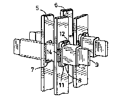
Figure 1 is an isometric view of load buses passing
through riser buses and supported by the riser buses;
Figure 2 is an isometric view of a support block
incorporated in the assembly illustrated in Figure l; and
Figure 3 is a sectional view of the portion of the
load bus where it passes through the riser bus.
DESCRIPTION OF THE PREFERRED EMBODIMENT
Considering first Figure 1, there is shown two pairs
of riser buses 5 and 6 having apertures therein, designated
7 and 8, through which passes the load bus 9. The load bus 9
is supported in aperture 8 by means of a pair of grommet blocks
11 and 12, having a "U" shape, as illustrated in Figure 2.
It will be seen that the outer surface of the grommet
b-ock 11 is shaped to conform to aperture 8 and occupy slightly
less than half the perimeter of the aperture. A similar grommet
block 12 occupies the other half perimeter of aperture 8. A
pair of longitudinal projections 13 and 14 project from the
outer surface of grommet block 11 and~are spaced apart a distance
substantially equal to the thickness of riser bus 6. An insula-
ting sleeve 15 surrounds load bus 9 and conforms to the inner
surface of grommet block 11. The height of prajections 13 and
14 and the space between the grommet blocks 11 and 12.are such
as to permit the grommet blocks to be inserted in aperture 8
after the load bus 9 has been passed through aperture 8. Sleeve
15 is now passed over bus 9 and fills the space between bus 9
and grommet blocks 11 and 12 and holds them firmly outwards
so they conform to the inner surface of aperture 8 and the
projections 13 and 14 snuggly engage the surfaces of riser bus 6.
.

416
3 CW-1115
As shown in Figure 3, in the assembled condition,
load bus 9 is surrounded by sleeve 15 which snuggly fits over
the load bus. The two grommet blocks 11 and 12 fit snuggly
over sleeve 15 and fit within the aperture 8 in riser bus 6.
A similar projection on grommet block 12 engages the surface
of riser bus 6 on the other side of aperture 8. The buses
may be assembled by passing load bus 9 through riser buses
as required. Subsequently, a suitable number of grommet bloc~s
11 and 12 may be slipped into the aperture between the load bus
and the riser bus. Sleeve 15 may then be slipped over the load
bus locking the grommet blocks in place and ensuring that the
load bus is snuggly supported by the riser bus. As will be
seen, since the load bus is supported by the riser bus, which
in turn has been rigidly supported from the framework of the
assembly, there is no need for further support of the load buses,
thus, eliminating the large and expensive support insulator
blocks previously required.
The grommet blocks may be made of any suitable, rela-
tively rigid, insulating material, which will firmly support
the load buses in the riser buses. The sleeve material may be
similarly selected from a suitable somewhat resilient insulating
sleeving. Since all the grommet blocks and sleeves are sub-
stantially identical and may be put in place after the instal-
lation of the buses, the assembly is obviously economical and
convenient.
While the grommet blocks have been shown to have the
specific conformation it will be apparent that variations can
be made within the scope of this invention. For example, the
air space between the two grommet blocks 11 and 12 is shown in
vertical arrangement. It is evident that under some circum-
stances it may be more convenient to rearrange the projections
and air spaces and separate the blocks horizontally rather than
vertically. It is also apparent that the sleeve-15, while shown
as a single_piece sleeve, might under some circumstances be
replaced by a two_piece sleeve, split either horizontally or in
a vertical plane for convenience of assembly.

Dessin représentatif
Une figure unique qui représente un dessin illustrant l'invention.
États administratifs

2024-08-01 : Dans le cadre de la transition vers les Brevets de nouvelle génération (BNG), la base de données sur les brevets canadiens (BDBC) contient désormais un Historique d'événement plus détaillé, qui reproduit le Journal des événements de notre nouvelle solution interne.

Veuillez noter que les événements débutant par « Inactive : » se réfèrent à des événements qui ne sont plus utilisés dans notre nouvelle solution interne.

Pour une meilleure compréhension de l'état de la demande ou brevet qui figure sur cette page, la rubrique Mise en garde , et les descriptions de Brevet , Historique d'événement , Taxes périodiques et Historique des paiements devraient être consultées.

Historique d'événement

Description Date
Inactive : Périmé (brevet sous l'ancienne loi) date de péremption possible la plus tardive 2009-02-25
Inactive : CIB de MCD 2006-03-11
Accordé par délivrance 1992-02-25

Historique d'abandonnement

Il n'y a pas d'historique d'abandonnement

Titulaires au dossier

Les titulaires actuels et antérieures au dossier sont affichés en ordre alphabétique.

Titulaires actuels au dossier
WESTINGHOUSE CANADA INC.
Titulaires antérieures au dossier
KENNETH NIM-PUN LAM
ROBERT A. WILSON
Les propriétaires antérieurs qui ne figurent pas dans la liste des « Propriétaires au dossier » apparaîtront dans d'autres documents au dossier.
Documents

Pour visionner les fichiers sélectionnés, entrer le code reCAPTCHA :


Pour visualiser une image, cliquer sur un lien dans la colonne description du document (Temporairement non-disponible). Pour télécharger l'image (les images), cliquer l'une ou plusieurs cases à cocher dans la première colonne et ensuite cliquer sur le bouton "Télécharger sélection en format PDF (archive Zip)" ou le bouton "Télécharger sélection (en un fichier PDF fusionné)".

Liste des documents de brevet publiés et non publiés sur la BDBC .

Si vous avez des difficultés à accéder au contenu, veuillez communiquer avec le Centre de services à la clientèle au 1-866-997-1936, ou envoyer un courriel au Centre de service à la clientèle de l'OPIC.

({010=Tous les documents, 020=Au moment du dépôt, 030=Au moment de la mise à la disponibilité du public, 040=À la délivrance, 050=Examen, 060=Correspondance reçue, 070=Divers, 080=Correspondance envoyée, 090=Paiement})


Description du
Document 
Date
(aaaa-mm-jj) 
Nombre de pages   Taille de l'image (Ko) 
Abrégé 1993-10-26 1 12
Revendications 1993-10-26 3 71
Dessins 1993-10-26 1 17
Description 1993-10-26 3 121
Dessin représentatif 2000-12-05 1 8
Taxes 1997-01-13 1 68
Taxes 1996-01-11 1 79
Taxes 1995-01-17 1 58
Taxes 1993-12-28 1 125