Note : Les descriptions sont présentées dans la langue officielle dans laquelle elles ont été soumises.
~2969QZ
The present invention relates to a toy vehicle
having a wheelecl chassis adapted to travel on roadways and a
body adapted to be secured to the said chassis.
In the case of known toy vehicles, the body is
mde to a predetermined design and is connected to the
chassis inconveniently with bent tabs or clamping means.
Apart from the fact that such toys need access to their
interiors, either to replace the power source or to make
repairs, it is also essential to retain the body. Changing
the body is either impossible, involves complex adaptation
to the chassis, or requires a chassis adapted to the body.
It is the purpose of the invention to provide
means for fitting bodies of any kind to the chassis, while
retaining the same chassis.
According to the present invention, there is there
fore provided a toy vehicle having a wheeled chassis
adapted to travel on roadways and a body adapted to be
secured to the chassis, wherein the chassis comprises, on
the body side, a series of pins spaced from each other,
while the body comprises, on the chassis side, a series of
arrangement of the sleeves, matching the pins and adapted to
engage frictionally therewith.
The pins and sleeves are preferably arranged in
rows on the chassis and on the body, a multi-row arrangement
of both the pins and the sleeves having been found
advantageous and producing stable connections. This makes
it possible to fit various bodies to a given chassis by a
simple plug-in procedure. Moreover, the body selected may
be fitted to, or removed from the chassis without the use of
tools. For the purpose of equalizing tolerances, the pins
are preferably provided with locating webs projecting from
the peripheral surfaces thereof, so that when the sleeves
are pushed over the pins, a clamping fit is obtained by
deformation. It is to be understood that the locating webs
A~ 1
12969C~2
may also be provided on the inner peripheral surfaces of the
sleeves, whereas the outsides of the pins are smooth.
According to a preferred embodiment, the chassis
is in the form of a box consisting of two parts arranged one
above the other and adapted to be united in a plane parallel
with the plane of the roadway, the union being effected by
means of pins arranged upon one part of the chassis and
sleeves adapted to be pushed onto the pins and arranged on
the other part of the chassis. The chassis thus formed
serves not only to mount the wheels, but also to accommodate
the source of power, the transmission and the drive-motor.
It is preferable for one of the chassis-parts to
be provided with a compartment for the accommodation of the
drive-motor, whereas the other part of the chassis
accommodates the transmission, at least a part of the
electrical conductors, and a switching means. Areas moulded
onto, or pinched into, the chassis-parts may serve to hold
down the source of power and electrical conductors in the
form of loosely inserted strip-conductors, for example.
The drive-motor may be mounted in the compartment
in one part of the chassis by clamps. The electrical
connection between the drive-motor and the electrical
conductors is effected merely by pressing one against the
other (bearing contact).
According to another preferred embodiments, the
two chassis-parts are provided with half-shells constituting
bearings for the wheels and wheel-shafts of the vehicle.
The front wheels in particular may be mounted in two similar
half-shells arranged one above the other, the one being
arranged on an extension of the upper chassis-part and the
other on the lower chassis-part. The rear wheels, however,
are preferably secured to a shaft running in recesses in the
two chassis-parts.
Provision may also made for each of the front
12g6902
wheels of the vehicle ~o engage with a cylindrical stub-axle
freely rotatable in the half-s}le~ls and for the stub-axles
to be provided, in order to locate the wheels axially in the
half-shells, with an annular element, or annular-element
sections, projecting beyond the peripheral surfaces of the
stub-axles and engaging in annular grooves in the half-
shells. The stub-axles are preferably made of sections of
tubes or sleeves. This arrangement makes it possible to
mount the wheels merely by plugging them in. The relatively
large diameter of the stub-axles ensures little play in the
wheel-mountings, while the annular element, or annular-
element sections, keep axial bearing play within narrow
limits. The wheels may be fitted to the chassis without
tools and the usual shaping of metal parts as axles and
shafts is eliminated.
According to a preferred embodiment, the half-
shelles may be fitted to each other immovably by means of
tongues and grooves formed in the common parting surfaces
and running axially and transversely of the longitudinal
axes of the half-shells. To this end, one half-shell
preferably carries. It is also possible to provide each
half shell with a tongue and a diametrically opposite
groove.
It is to be understood that the annular elements
and annular grooves may be of any desirable cross-sectional
shape and cross-sectional size. According to a preferred
example of embodiment, the annular elements and annular
grooves are of trapezoidal cross-section. By supporting
each other mutually, the wedge-surfaces of the trapezium
allow the wheels to be mounted on the chassis with
particularly little play. It is possible for the annular
elements and annular grooves to be semi-circular in cross-
section.
~ - 3 -
-
~2g6~0~
The inventi.on also prov:ides a 1-oy vehicle
comprising: a chassis whicll is adapted to travel by means of
wheels on a d.riving surface; a body is adapted to be
fastened on the chassis the vehicle chassis comprising a
plurali.ty of first pins fixed on -the side towards the body
at a distance adjacen-t to each o-ther; the vehicle body
comprising a plurality of first sleeves fixed on the side
towards the chassis at the same distance and in relation to
-the plurality of first pins which can be pushed onto the
plurality of first pins of the vehicle chassis so they are
frictionally engages; the vehicle chassis being formed
boxlike by two vehicle chassis parts disposed on top of each
other and connectable in a plane parallel to the plane of a
driving surface, both of which are connected by means of
second pins disposed on one chassis part and second sleeves
provided on the other chassis part which can be pushed on
the second pins wherein the one chassis part comprises a
reception chamber containing a low voltage power source and
a reception space containing a drive motor and the other
chassis part comprises electric conductors extending into
the reception chamber and a switching device providing or
interrupting electrical contact between the drive motor and
one of the electric conductors.
Preferred embodiments are described hereinafter as
- 3a -
1'~96902
examples without limitative manner having reference the
attached drawings, wherein:
Fig. 1 is a side elevation of a travelling toy;
Fig. 2 is a side elevation of a lower chassis-
part;
Fig. 3 is a plan view of a chassis-part according
to Fig. 2;
Fig. 4 is a side elevation of an upper chassis-
part;
Fig. 5 is a side elevation of a body;
Fig. 6 is a cross-section along the line VI-VI in
Fig. l;
Fig. 7 is a side elevation of a lower chassis-part
of another design;
Fig. 8 is a plan view of a lower chassis-part of
another design;
Fig. 9 is a side elevation of an upper chassis-
part of another design;
Fig. 10 is a side elevation of a wheel, to an
enlarged scale and partly sectioned;
Fig. 11 is a part-section of a chassis to an
enlarged scale; and
Fig. 12 is a cross-section along the line XII-XII
in Fig. 10, to an enlarged scale.
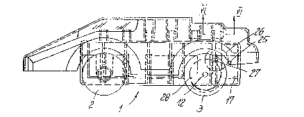
In Fig. 1, 1 is the chassis which can travel in
known fashion on roadways (not shown) by means of front
wheels 2 and rear wheels 3, 4 is a body of any suitable
design which is connected to chassis 1. In this embodiment,
chassis 1 consists of a lower part 1' and an upper part ~"
which jointly produce a box-like chassis. Chassis-part 1'
and 1" may be connected together by a sliding process
whereby pins 5 arranged on chassis part 1" slide
frictionally into sleeves 6 on chassis-par~ 1'. In the
vicinity of the front end, on both sides, chassis-part 1' is
1~9~9(~Z
provided with half-shells 7 which, when chassis-part 1",
carrying half-shells 7' arranged on extensions 8, is fitted,
make up the wheel-bearings. Furthermore, in the vicinity of
further recesses 10 chassis-part 1' comprises a half-
5 bearing-aperture 11 for drive-shaft 12 of rear wheels 3.
When the two chassis-parts are connected together, further
extensions 13, with half-bearing-apertures 14, enter
recesses 10. Mounted within chassis-part 1 are connecting
springs 15,15' which may be connected, through electrical
10 conductors 16,16', to a drive-motor 17. Chassis-part 1"
accommodates, in a compartment 32, a battery (not shown) and
is provided with a compartment 33 for the said drive-motor.
Electrical conductor 16 is connected to drive-motor 17 by
pressing the former against an insulated contact 18 on the
15 said drive-motor, while electrical conductor 16' is
connected by means of a sliding switch 19 adapted to move
longitudinally in a recess 20 in chassis-part 1. The
switch has a wedge-shaped extension 21 which lifts
electrical conductor 16' out of a bend 22 during the sliding
20 movement and presses the free end of the conductor against
another motor-contact, e.g. the motor housing, 23 are webs
for locating electrical conductors 16,16' while 24 are
moulded-on parts for located the said conductors in chassis
part 1'.
Drive-motor 17 acts, through a pinion 25, upon a
gearwheel 26 and a pinion 27 which meshes with a further
gearwheel 28 secured to drive-shaft 12 of rear wheels 3.
The top of chassis-part 1" carries pins 29 which,
in this particular example are arranged in two rows side by
30 side. Body 4 is adapted to be connected to chassis 1 by
means of sleeves 30 which are pushed over pins 29 (Fig. 1).
For the purpose of equalizing tolerances, pins 29 may
comprise locating webs 31 in their outer peripheral
surfaces, the webs ensuring, by deformation, reliable
:12969~2
attachment o~ the body t-o the chassis.
In this travelling toy, front wheels 2 rotate upon
chassis l freely and independently. To this end, and as
shown in particular in Fig. 10, front wheels 2 are mounted
upon stub-axles 37 in -the form of sections of tubes or
sleeves which rotate freely in bearings in the form of half-
shells 7,7' on chassis 1. For the purpose of locating front
wheels 2 axially, stub-axles 37 are provided with an annular
element, or annular-element sections, 38 which project
beyond the peripheral surfaces of the stub-axles and engage
in annular grooves 39 in half-shells 7,7'.
for mutual alignment of half-shells 7,7', one
half-shell carries tongues 40 and the other grooves 41. By
fitting tongues 40 into grooves 41, alignment is effected by
a simple sliding operation.
For the purpose of attaching front wheels 2, it is
assumed, first of all, that chassis-parts l' and l" are held
one above the other with a space between them. This makes
it possible for the front wheels, with their stub-axles 37,
to be placed in lower half-shells 7'. The upper chassis-
part is then pushed down so that the upper half-shells form
closed bearings with the lower half-shells in which the
stub-axles are held by annular elements 38 and are thus
free, or almost free, of axial play.
In the embodiment according to Fig. 12, annular-
element sections 38' are arranged on stub-axles 37 for the
purpose of locating front wheels 2.
.~
~'`-"~
-