Sélection de la langue

Search

Sommaire du brevet 1297311 

Énoncé de désistement de responsabilité concernant l'information provenant de tiers

Une partie des informations de ce site Web a été fournie par des sources externes. Le gouvernement du Canada n'assume aucune responsabilité concernant la précision, l'actualité ou la fiabilité des informations fournies par les sources externes. Les utilisateurs qui désirent employer cette information devraient consulter directement la source des informations. Le contenu fourni par les sources externes n'est pas assujetti aux exigences sur les langues officielles, la protection des renseignements personnels et l'accessibilité.

Disponibilité de l'Abrégé et des Revendications

L'apparition de différences dans le texte et l'image des Revendications et de l'Abrégé dépend du moment auquel le document est publié. Les textes des Revendications et de l'Abrégé sont affichés :

  • lorsque la demande peut être examinée par le public;
  • lorsque le brevet est émis (délivrance).
(12) Brevet: (11) CA 1297311
(21) Numéro de la demande: 1297311
(54) Titre français: REFROIDISSEUR DE LIQUIDE
(54) Titre anglais: LIQUID COOLERS
Statut: Périmé et au-delà du délai pour l’annulation
Données bibliographiques
(51) Classification internationale des brevets (CIB):
  • B67D 7/80 (2010.01)
  • B67D 1/08 (2006.01)
  • F25B 39/02 (2006.01)
  • F25D 31/00 (2006.01)
(72) Inventeurs :
  • HILTON, ROY GEORGE (Australie)
(73) Titulaires :
  • GSA INDUSTRIES (AUST.) PTY. LTD.
(71) Demandeurs :
(74) Agent: LAVERY, DE BILLY, LLP
(74) Co-agent:
(45) Délivré: 1992-03-17
(22) Date de dépôt: 1988-04-12
Licence disponible: S.O.
Cédé au domaine public: S.O.
(25) Langue des documents déposés: Anglais

Traité de coopération en matière de brevets (PCT): Non

(30) Données de priorité de la demande:
Numéro de la demande Pays / territoire Date
PI 1408 (Australie) 1987-04-13
PI 5864 (Australie) 1987-12-11

Abrégés

Abrégé anglais


A B S T R A C T
A fluid cooler comprising:
(i) a housing having an inlet and an outlet for
refrigerant and an inlet and an outlet for fluid to be
cooled;
(ii) a chamber located in the housing and in
engagement with the housing about the inlet for
refrigerant, the chamber having openings therein to permit
refrigerant to pass from the chamber into a space defined
between the housing and the chamber;
(iii) a conduit for passage of fluid to be cooled
therethrough, the conduit located within the space and
extending from the inlet to the outlet for the fluid to
be cooled, and
(iv) a float controlled valve located in the
chamber for control of ingress of liquid refrigerant into
the chamber.

Revendications

Note : Les revendications sont présentées dans la langue officielle dans laquelle elles ont été soumises.


- 7 -
THE CLAIMS DEFINING THE INVENTION ARE AS FOLLOWS:
1. A fluid cooler comprising:
(i) a housing having an inlet and an outlet for
refrigerant and an inlet and an outlet for fluid to be
cooled;
(ii) a chamber located in the housing and in
engagement with the housing about the inlet for refrigerant,
the chamber having openings therein to permit refrigerant to
pass from the chamber into a space defined between the
housing and the chamber;
(iii) a conduit for passage of fluid to be cooled
therethrough, the conduit located within the space and
extending from the inlet to the outlet for the fluid to be
cooled, and
(iv) a float controlled valve located in the
chamber for control of ingress of liquid refrigerant into
the chamber.
2. A fluid cooler according to claim 1 wherein the
chamber located in the housing sealingly engages the housing
about the inlet for refrigerant.
3. A fluid cooler according to claim 1 wherein the
conduit extends about the chamber.
4. A fluid cooler according to either claim 1 or claim
3 wherein the conduit is coiled.
5. A fluid cooler according to claim 1 wherein the
chamber extends substantially the length of the housing.
6. A fluid cooler according to claim 1 wherein the
openings in the chamber are distant from the inlet for
refrigerant.

Description

Note : Les descriptions sont présentées dans la langue officielle dans laquelle elles ont été soumises.

~733L~L
-- 2
LIQUID COOLERS
This invention relates to liquid coolers for
cooling beverages such as beer.
The device to which this invention is directed is
an evaporator of refrigerant there being a conduit in the
housing through which the liquid beverage is directed.
It is conventional to have a float within the
housinq so that entry of liquid refrigerants is controlled
depending upon the height of the liquid within the housing.
Care must be taken to guard against mechanical
breakdown of components in the event of certain operating
conditions arising. Such breakdown conditions can be
brought about by the introduction of warm or even hot liquid
through the beverage cooling coils potentially causing a
lS very substantial pressure build-up in the housing.
Conventionally a float suppoct is provided in a
lowermost portion of the housing upon which the float in a
lowermost position can rest so that this support deflnes the
lowermost position of the float.
However, in the event of the substantial pressure
arising, the float suppoct may collapse and the float can
fall further downwards. Consequently the float can either
~am or fall completely from its sliding retaining means in
the event of a very low evaporative liquid level
25 eventuating.
In the event of such malfunction the housing being
a sealed unit must be removed in its entirety and returned
to a factory for total dismantling and reconstruction.
In Australian Patent No. 468170 one approach toward
30 overcoming the susceptibility of these devices to the
effects of excessive pressure within the housing is
disclosed. sriefly a float controlled valve is suggested
having a liquid needle valve assembly depending from an
upper portion of the housing. The float was retained with
35 the valve assembly to close said valve when the float was at
an uppermost position, and when the float iB at a lowermost
.

~2~3~3~L~
position the float was supported from an ~pper part of the
housing by direct engagement of the float wlth such upper
part of the housing. This device has served to mlnimize the
malfunction of the float valve and therefore the liquid
S cooler.
Nevertheless other problem6 are still as~ociated
with these improved liquid coolers. The first arise~ when
the coolers are utilized during high summer temperatures
where the condensing capacity of the condensing units is too
10 small or blocked. In such circumstances liquid refrig~rant
of abnormally high temperature will be introduced to the
cooler resulting in significant losses in cooling
efficiency. The second problem ari~es if the beverage
freezes in the coils. This normally results in the coils
15 distorting which can ~am up agalnst the float system
rendering it inoperative.
In an effort to minimige these problems it is
proposed to at least partially isolate the float control
valve by placing a chamber about it.
Accordingly there is provided a fluid cooler
comprising
(i~ a housing having an inlet and an outlet for
refrigerant and an inlet and an outlet for
fluid to be cooled,
25(ii) a chamber located in the housing and in
enqagement with the housing about the inlet
for refrigerant, the chamber having openings
therein to permit refrigerant to pass from the
chamber into a space defined between the
housing and the chamber,
(iii) conduit for passage of fluid to be cooled
therethrough, the conduit located within the
space and extending from the inlet to the
outlet for the fluid to be cooled, and

~2~ 3~
(iv) a float controlled valve located in th0
chamber for control of ingress of refrigerant
into the chamber.
As the inlet for refrigerant is located to directly
permit the refrigerant in 11quid form to enter the chamber,
the chamber will act as a pre-chilling chamber for the hot
liquid refrigerant to cool down before being brought in
contact with the fluid conduit. sy equalizing the
refrigerant temperature in both sections of the housing i.e.
10 the space and chamber, the capacity of the cooler increases.
Further as the chamber is interposed between the
coiled conduit and the float valve any distortion of the
conduit due to freezing will not cause the float valve to
jam.
Advantageously, the chamber located in the hou6ing
engages the housing about the inlet for liquld refrigerant.
Apertures are provided to allow gaseous refrigerant to pass
and equalization of the chamber and space. Liquid
refrigerant will travel through the chamber and will be
20 pre-chilled before it passes through the openings to the
space. To maximise the heat exchange effect, the chamber
may be extended substantially the length of the housing. In
such an arrangement the openings in the chamber may be
located adjacent to the far end of the chamber and the
25 refrigerant is therefore exposed to cooling for as long a
period as is possible to maximize equalization of
temperature with the refrigerant already circulating in the
space and about the conduit.
Again in an effort to maximise the cooling
30 efficiency of the cooler, the conduit is made to extend
about the chamber preferably as a coil. The coil will
usually surround a major amount of the outer surface of the
chamber.
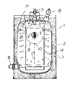
The invention is further illustrated with the
35 assistance of the accompanying drawings in which:
Fiqure 1 is a cross-sectional view through a fluid
cooler according to the invention.

3~3L
- 5 -
Figure 2 is a plan view of the fluid cooler of
Fig. l.
Referring now to the drawings, the fluid cooler l
has a housing 2 contained within an insulating surround 3.
The housing 2 has a liquid needls valve assembly 4
which extends from inlet 5. The needle valve a6sembly 4
includes a needle valve 6. ~ float 7 which is comprised of
a metal shell ~ and an internal pressurized foam plastic
material 9 has a tubular vertical sleeve 10 into which the
liquid needle valve assembly 4 is located.
Cylindrical chamber ll is located about and clear
from float 7. T}le chamber 11 has upper edge6 12 fixed to
housing 2. The side of cylindrical chamber 11 extends
downwardly from the inlet 5 for liquid refrigerant and
ceases just above the bottom of housing 2. Openings 13 in
the lower part of cylindrical chamber 11 permit liquid
refrigerant to escape into space 14 defined by the chamber
11 and housing 2.
Fluid coiled conduit 15 totally envelope chamber
2011, though for ease of understanding of the drawing the
lower and upper portions of conduit 15 are only shown.
Conduit 15 extends from inlet 16 to outlet 17 and fluid to
be cooled passes into this conduit 15 via inlet 16,
circulates about chamber 11 and escapes via outlet 17.
2sDuring this passage the fluid is cooled by heat exchange
with the refrigerant located in the space 14.
The liquid refrigerant is up to level 20. As the
initial refrigerant must first pass through the chamber 11
beEore exiting into space 14, it is pre-chilled by heat
30exchange and its temperature equalized with that of the
refrigerant in space 14 which is ultimately removed from
housing 2 via refrigerant return lB. Apertures 19 are
provided at the top of chamber 11 to allow gaseous
refrigerant in the chamber 11 to pass into the space 14.
3~hese apertures 19 also permit pressure equalization of the
chamber 11 and space 14.
Accordingly the incorporation of the pre-chill

g73~L
-- 6
chamber into the cooler not only protects the float valve
mechanism from damage but more importantly allows unsuitably
warm liquid refrigerant to be pre-chilled prior to contact
with fluid carrying conduits. This results in significant
S increases in the efficiency of the cooler and also
substantially improves the working life of the cooler
especially its valve mechanism.

Dessin représentatif
Une figure unique qui représente un dessin illustrant l'invention.
États administratifs

2024-08-01 : Dans le cadre de la transition vers les Brevets de nouvelle génération (BNG), la base de données sur les brevets canadiens (BDBC) contient désormais un Historique d'événement plus détaillé, qui reproduit le Journal des événements de notre nouvelle solution interne.

Veuillez noter que les événements débutant par « Inactive : » se réfèrent à des événements qui ne sont plus utilisés dans notre nouvelle solution interne.

Pour une meilleure compréhension de l'état de la demande ou brevet qui figure sur cette page, la rubrique Mise en garde , et les descriptions de Brevet , Historique d'événement , Taxes périodiques et Historique des paiements devraient être consultées.

Historique d'événement

Description Date
Inactive : CIB désactivée 2011-07-26
Inactive : CIB de MCD 2010-02-01
Inactive : CIB dérivée en 1re pos. est < 2010-02-01
Inactive : CIB dérivée en 1re pos. est < 2010-01-30
Inactive : CIB expirée 2010-01-01
Inactive : CIB de MCD 2006-03-11
Le délai pour l'annulation est expiré 1998-03-17
Lettre envoyée 1997-03-17
Accordé par délivrance 1992-03-17

Historique d'abandonnement

Il n'y a pas d'historique d'abandonnement

Titulaires au dossier

Les titulaires actuels et antérieures au dossier sont affichés en ordre alphabétique.

Titulaires actuels au dossier
GSA INDUSTRIES (AUST.) PTY. LTD.
Titulaires antérieures au dossier
ROY GEORGE HILTON
Les propriétaires antérieurs qui ne figurent pas dans la liste des « Propriétaires au dossier » apparaîtront dans d'autres documents au dossier.
Documents

Pour visionner les fichiers sélectionnés, entrer le code reCAPTCHA :


Pour visualiser une image, cliquer sur un lien dans la colonne description du document. Pour télécharger l'image (les images), cliquer l'une ou plusieurs cases à cocher dans la première colonne et ensuite cliquer sur le bouton "Télécharger sélection en format PDF (archive Zip)" ou le bouton "Télécharger sélection (en un fichier PDF fusionné)".

Liste des documents de brevet publiés et non publiés sur la BDBC .

Si vous avez des difficultés à accéder au contenu, veuillez communiquer avec le Centre de services à la clientèle au 1-866-997-1936, ou envoyer un courriel au Centre de service à la clientèle de l'OPIC.


Description du
Document 
Date
(aaaa-mm-jj) 
Nombre de pages   Taille de l'image (Ko) 
Page couverture 1993-10-27 1 13
Abrégé 1993-10-27 1 29
Revendications 1993-10-27 1 29
Dessins 1993-10-27 1 39
Description 1993-10-27 5 166
Dessin représentatif 2001-11-22 1 19
Taxes 1995-02-07 1 33
Taxes 1996-02-12 1 26
Taxes 1994-03-15 1 24