Sélection de la langue

Search

Sommaire du brevet 1298057 

Énoncé de désistement de responsabilité concernant l'information provenant de tiers

Une partie des informations de ce site Web a été fournie par des sources externes. Le gouvernement du Canada n'assume aucune responsabilité concernant la précision, l'actualité ou la fiabilité des informations fournies par les sources externes. Les utilisateurs qui désirent employer cette information devraient consulter directement la source des informations. Le contenu fourni par les sources externes n'est pas assujetti aux exigences sur les langues officielles, la protection des renseignements personnels et l'accessibilité.

Disponibilité de l'Abrégé et des Revendications

L'apparition de différences dans le texte et l'image des Revendications et de l'Abrégé dépend du moment auquel le document est publié. Les textes des Revendications et de l'Abrégé sont affichés :

  • lorsque la demande peut être examinée par le public;
  • lorsque le brevet est émis (délivrance).
(12) Brevet: (11) CA 1298057
(21) Numéro de la demande: 1298057
(54) Titre français: CAPUCHON DE POTEAU
(54) Titre anglais: POST COVER
Statut: Périmé et au-delà du délai pour l’annulation
Données bibliographiques
Abrégés

Abrégé anglais


ABSTRACT OF THE DISCLOSURE
A cover for a post, beam or other elongate
object is formed by interengagement of projections
extended along a longitudinal edges of four elongate
cover members assembled around the object. The projec-
tions include interengageable hook-shaped cross-sectional
shapes and are provided at the edges of flat body por-
tions, having longitudinal ribs formed on major surfaces
thereof for spacing the body portions from the surfaces
of the object. The cover members are made of plastic by
an extrusion process.
-10-

Revendications

Note : Les revendications sont présentées dans la langue officielle dans laquelle elles ont été soumises.


The embodiments of the invention in which an
exclusive property or privilege is claimed are defined as
follows:
1. A cover member for an elongate object,
said cover member being intended for use with a plurality
of other cover members for assembly around the object and
said cover member comprising:
an elongate generally sheet-shaped body
portion;
means extending along opposite longitudinal
edges of said body portion for securing said longitudinal
edges to juxtaposed longitudinal edges of adjacent ones
of the cover members when said cover member is assembled
with said other cover members to form a covering around
the object; and
reinforcement formations extending along said
body portion for strengthening said body portion.
2. A cover member as claimed in claim 1,
wherein said reinforcement formations comprise a plura-
lity of spacer projections at one major surface of said
body portion for spacing said major surface from the sur-
face of the object.
3. A cover member as claimed in claim 1,
wherein said securing means comprise a first and second
-7-

edge projections defining a U-shaped recess adjacent one
longitudinal edge of said body portion and a single third
edge projection at the other longitudinal edge of said
body portion, said third edge projection being interenga-
geable in the U-shaped recess of like first and second
projections of a like cover member.
4. A cover member as claimed in claim 2,
wherein said first edge projection comprises an outer
flange-shaped projection along said one longitudinal
edge, said second edge projection is parallel to and
spaced from said first projection, said second projection
having a hook-shaped cross-section, and said third edge
projection is elongate and is hook-shaped in cross-
section, said third projection being interengageable with
a like second projection of a like cover member.
5. A cover member as claimed in claim 1, 2 or
3, wherein said reinforcement formations comprise ribs on
said body portion.
6. A cover member as claimed in claim 1
formed as an extrusion.
7. A cover member as claimed in claim 5,
wherein said reinforcement formations comprise ribs on
said major surface of said body portion.
-8-

8. A cover member as claimed in claim 6 made
of plastic material.
9. A post cover, comprising a cover member as
claimed in claim 1, 2 or 3 assembled with three other
like cover members with adjacent ones of the cover mem-
bers connected together along their longitudinal edge
portions by interengagement of the securing means and
with the reinforcement formations interposed between the
object and the body portions of the cover members.
-9-

Description

Note : Les descriptions sont présentées dans la langue officielle dans laquelle elles ont été soumises.

lZg8~57
7723-1
The present invention relates to post covers
and to cover members for assembly with a plurality of
like cover members to form a cover about an elongate
object, e.g. a post, beam or the like.
In the building construction industry and other
fields, there exists a need for providing a cover about
posts and the like, e.g. square-section posts of nominal
6 X 6 dimensions, in order to protect the posts and to
improve the aesthetic appearance thereof.
It is, accordingly, an object of the present
invention to provide a novel and improved cover member
for a post.
The present invention provides a cover member
for an elongate object, the cover member being intended
for use with a plurality of other cover members for
assembly around the object and the cover member
comprising: an elongate generally sheet-shaped body
portion, means extending along opposite longitudinal
edges of the body portion for securing the longitudinal
edges to juxtaposed longitudinal edges of adjacent ones
of the cover members when the cover member is assembled
with the other cover members to form a covering around

~298C~5~
the object, and reinforcement formations extending along
the body portion for strengthening the body portion.
In one embodiment of the invention, the
securing means comprise edge projections defining a
U-shaped recess along one longitudinal edge of the body
portion, with a single edge projection along the other
edge of the body portion, this single edge projection
being interengageable in the U-shaped recess of an adja-
cent, similar cover member for connecting together the
cover members at their longitudinal edges. Preferably,
the edge projections include, along the other longitudi-
nal edge of the cover member, a projection of hook-shaped
cross-section, which is interengageable with a like pro-
jection on an adjacent, like cover member.
The spacer projections may comprise longitudi-
nal ribs on the body portion, and these ribs may be
formed in one piece with the body portion in, for
example, a plastic extrusion process.
The invention will be more readily understood
from the following description of the preferred embodi-
ment thereof given, by way of example, with reference to
the accompanying drawing, in which,-
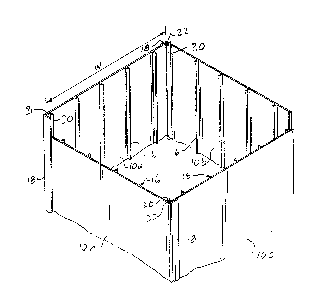
Figure 1 shows a broken-away view in perspec-
tive of a post cover embodying the present invention and
assembled around a post;
--2--

1'~9~3~57
Figure 2 shows a broken-away view in perspec-
tive of the post cover of Figure 1, with the post omitted
to show the shape of the interior of the post cover; and
Figure 3 shows a broken-away end view of a pair
of cover members forming parts of the post cover of
Figures 1 and 2.
The post cover illustrated in the drawings
comprises four cover members 10a, 10b, 10c and 10d which
are identical to one another and, therefore, only one of
which, namely the cover member 10a, will be described in
detail. The cover members 10a - 10d have smooth outer
surfaces 11 and may be made of any design colour. Also,
the outer surfaces 11 may be modified by providing a
design formation to provide an aesthetically plea~ing
appaarance.
The post cover member 10a comprises a body por-
tion 12 in the form of a flat, elongate, sheet-shaped
body portion.
In practice, the cover member 10a i9 cut to
length, to suit its intended location of use on a post
14. The width of the cover member 10a, indicated as
width W in Figure 2, is slightly greater than the width w
of the post 14 so as to enable longitudinal ribs 16 on a
opposed pairs of the cover members 10a - 10d to re~t

12g8~57
against the opposite surfaces of the post 14. The inven-
tion is not restricted to any particular post size.
The cover member 10a is formed, along one
longitudinal edge thereof, with a pair of elongate pro-
jections 18 and 20, which are perpendicular to a major
surface 19 of the body portion 12 and define between them
a U-shaped recess 21, the ribs 16 likewise being perpen-
dicular to the surface 21.
The projection 18 formed at the extreme edge of
the body portion 12 as an edge flange.
Spaced inwardly from the extreme edge of the
body portion 12, the projection 20 is formed with a hook-
shaped cross-section, as can be seen from Figure 3.
The opposite longitudinal edge of the body por-
tion 10a is formed with a hook-shaped projection 22,
which is insertable into the U-shaped receqs 21 formed
between the projections 18 and 20 of the adjacent cover
member 10b, with the hook-shaped projection 20 inter-
engaged with the hook-shaped projection 22 in order to
releasably secure together the adjacent cover members 1Oa
and 1Ob.
When the four cover members 10a - 10b are
assembled as shown in Figure 1 around the post, with the

lZ98~57
projecting ribs 16 engaging the outer surfaces of the
post, these ribs 16 serve to space the inner surfaces of
the body portions 12 of the cover members 10a - 10b from
the surfaces of the post 14.
The ribs 16 project from the body portion 19 by
a distance which, added to the thickness of the body por-
tion 19, is at least equal to the spacing of the projec-
tion 20, including the thickness of the latter, from the
opposed side face of the flange 18, so that sufficient
space is provided beween the post and the flange 18 to
accommodate the projection 20.
The above-described cover members are pre-
ferably made of plastic material, e.g. PVC or the like,
by an extrusion process.
The ribs 16 serve not only to space the body
portion 19 from the post but also to strengthen the body
portion 19 so as to resist deformation of the cover
member when the cover member is exposed to hot weather.
The ribs 16 also prevent the cover members from rattling
on the post in response to the wind. However, it is also
feasible to provide ribs~ in addition to or instead o~
the ribs 16, on the outer surface 11 of the cover member.
Furthermore, instead of ribs, other reinforce-
ment formation, e.g. corrugations or channel-formations,
may be employed.
--5--

The invention is not restricted to cover mem-
bers for posts but may be employed for cover members for
other elongate objects, e.g. because, stair treads and
hand rails, and in the case of the latter may be curved
at their longitudinal edge portions.
The present cover members may be readily
removed from their post or other elongate object, e.g.
for reassembly elsewhere or to provide access to post or
the like.
As will be apparent to those skilled in the
art, various other modifications may be made in the
above-described embodiment of the invention, and accor-
dingly the invention is not restricted to the features of
this embodiment but may varied within the scope of the
appended claims.

Dessin représentatif
Une figure unique qui représente un dessin illustrant l'invention.
États administratifs

2024-08-01 : Dans le cadre de la transition vers les Brevets de nouvelle génération (BNG), la base de données sur les brevets canadiens (BDBC) contient désormais un Historique d'événement plus détaillé, qui reproduit le Journal des événements de notre nouvelle solution interne.

Veuillez noter que les événements débutant par « Inactive : » se réfèrent à des événements qui ne sont plus utilisés dans notre nouvelle solution interne.

Pour une meilleure compréhension de l'état de la demande ou brevet qui figure sur cette page, la rubrique Mise en garde , et les descriptions de Brevet , Historique d'événement , Taxes périodiques et Historique des paiements devraient être consultées.

Historique d'événement

Description Date
Inactive : CIB de MCD 2006-03-11
Inactive : Demande ad hoc documentée 1995-03-31
Le délai pour l'annulation est expiré 1994-09-30
Lettre envoyée 1994-03-31
Accordé par délivrance 1992-03-31

Historique d'abandonnement

Il n'y a pas d'historique d'abandonnement

Titulaires au dossier

Les titulaires actuels et antérieures au dossier sont affichés en ordre alphabétique.

Titulaires actuels au dossier
RODNEY L.A. ST. MARIE
Titulaires antérieures au dossier
S.O.
Les propriétaires antérieurs qui ne figurent pas dans la liste des « Propriétaires au dossier » apparaîtront dans d'autres documents au dossier.
Documents

Pour visionner les fichiers sélectionnés, entrer le code reCAPTCHA :


Pour visualiser une image, cliquer sur un lien dans la colonne description du document (Temporairement non-disponible). Pour télécharger l'image (les images), cliquer l'une ou plusieurs cases à cocher dans la première colonne et ensuite cliquer sur le bouton "Télécharger sélection en format PDF (archive Zip)" ou le bouton "Télécharger sélection (en un fichier PDF fusionné)".

Liste des documents de brevet publiés et non publiés sur la BDBC .

Si vous avez des difficultés à accéder au contenu, veuillez communiquer avec le Centre de services à la clientèle au 1-866-997-1936, ou envoyer un courriel au Centre de service à la clientèle de l'OPIC.

({010=Tous les documents, 020=Au moment du dépôt, 030=Au moment de la mise à la disponibilité du public, 040=À la délivrance, 050=Examen, 060=Correspondance reçue, 070=Divers, 080=Correspondance envoyée, 090=Paiement})


Description du
Document 
Date
(aaaa-mm-jj) 
Nombre de pages   Taille de l'image (Ko) 
Abrégé 1993-10-27 1 13
Revendications 1993-10-27 3 60
Dessins 1993-10-27 1 28
Description 1993-10-27 6 146
Dessin représentatif 2002-01-27 1 11