Sélection de la langue

Search

Sommaire du brevet 1298984 

Énoncé de désistement de responsabilité concernant l'information provenant de tiers

Une partie des informations de ce site Web a été fournie par des sources externes. Le gouvernement du Canada n'assume aucune responsabilité concernant la précision, l'actualité ou la fiabilité des informations fournies par les sources externes. Les utilisateurs qui désirent employer cette information devraient consulter directement la source des informations. Le contenu fourni par les sources externes n'est pas assujetti aux exigences sur les langues officielles, la protection des renseignements personnels et l'accessibilité.

Disponibilité de l'Abrégé et des Revendications

L'apparition de différences dans le texte et l'image des Revendications et de l'Abrégé dépend du moment auquel le document est publié. Les textes des Revendications et de l'Abrégé sont affichés :

  • lorsque la demande peut être examinée par le public;
  • lorsque le brevet est émis (délivrance).
(12) Brevet: (11) CA 1298984
(21) Numéro de la demande: 1298984
(54) Titre français: SYSTEME SERVANT A LA PRODUCTION DE GLACE
(54) Titre anglais: ICE MAKER SYSTEM
Statut: Périmé et au-delà du délai pour l’annulation
Données bibliographiques
(51) Classification internationale des brevets (CIB):
  • F25C 5/04 (2006.01)
(72) Inventeurs :
  • COLE, RONALD E. (Etats-Unis d'Amérique)
(73) Titulaires :
  • EMHART INDUSTRIES, INC.
  • EMERSON ELECTRIC CO.
(71) Demandeurs :
  • EMHART INDUSTRIES, INC. (Etats-Unis d'Amérique)
  • EMERSON ELECTRIC CO. (Etats-Unis d'Amérique)
(74) Agent: SWABEY OGILVY RENAULT
(74) Co-agent:
(45) Délivré: 1992-04-21
(22) Date de dépôt: 1987-01-26
Licence disponible: S.O.
Cédé au domaine public: S.O.
(25) Langue des documents déposés: Anglais

Traité de coopération en matière de brevets (PCT): Non

(30) Données de priorité de la demande:
Numéro de la demande Pays / territoire Date
06/888,875 (Etats-Unis d'Amérique) 1986-07-24

Abrégés

Abrégé anglais


M-6892
ICE MAKER SYSTEM
ABSTRACT OF THE DISCLOSURE
A timing mechanism controls various functions of an ice maker through
cams carried on a camshaft. A harvest rake that removes ice from a receptacle
is coupled to the camshaft to be rotated thereby. The camshaft is driven by a
motor which is coupled to the timing mechanism through a pair of non-circular
meshing gears. The gears are programmed such that a slower speed is imparted
to the camshaft when ice is being removed from the receptacle by the harvest
rake. This provides a slower speed but higher torque to the harvest rake
during ice removal and a faster, more accurate timing rate during filling of
the receptacle.

Revendications

Note : Les revendications sont présentées dans la langue officielle dans laquelle elles ont été soumises.


The embodiments of the invention in which an exclusive
property or privilege is claimed are defined as follows:
1. A timed drive means for an ice making system comprising:
cam means and switch means operated by said cam means,
ice removal means,
a motor, and
coupling means coupling said motor to said ice removal means to operate
same, including a motor output shaft connected to a first elliptical gear
through a first foci of same, and a second elliptical gear meshing with said
first elliptical gear and connected to said ice removal means through a second
foci of same,
said first and second elliptical gears programmed such that said first
foci is toward the area where they mesh, and said second foci is away from said
area during the ice removal, and
said first foci is away from said area and said second foci is toward said
area during liquid filling of said ice making system.
2. A drive means for an ice making system comprising:
cam means and switch means operated by said cam means;
ice removal means; and
means for driving said ice removal means at a first speed during ice
removal and at a second speed during liquid filling of the ice making system,
said second speed being faster than said first speed.
3. An ice making system comprising:
tray means for holding water while it is being frozen into ice;
rake means for mechanically removing said ice from said tray means; and
- 5 -

drive means for moving said rake from an initial position, through an ice
removing range in which it removes ice form said tray means, and thereafter
returning it to said initial position, said drive means including means for
driving said rake means at a first non-zero speed when it is removing said ice
from said tray means and at a second non-zero speed when it is being returned
to said initial position, said second speed being faster than said first speed.
4. An ice making system comprising:
tray means for holding water while it is being frozen into ice;
ice removal means; and
drive means for driving said ice removal means at a first non-zero speed
during ice removal and a second non-zero speed during at least a portion of the
time that ice is not being removed, said second speed being faster than said
first speed.
-6-

Description

Note : Les descriptions sont présentées dans la langue officielle dans laquelle elles ont été soumises.

34
The present invention relates to an ice maker system
for refrigerators and more particularly to such a system
wherein a harvest rake is driven at a variable speed.
Ice maker systems have been used in refrigerators for
many years. In such systems, a timing mechanism and a harvest
rake are driven by a motor. The timing mechanism controls
the on/off time of the system, heat to the system and other
related functions while the harvest rake is rotated to remove
ice from the ice maker.
In accordance with the present invention, a variable
speed is imparted to the harvest rake such that a slower
speed is applied during ice removal and higher speed during
liquid filling of the ice maker. This provides a higher
torque to the rake during ice removal and a faster more accu-
rate timing during filling.
Accordingly, the present invention relates to a timed
drive means for an ice making system which comprises cam means
and switch means operated by the cam means, a motor, and
coupling means coupling the motor to the cam means to operate
same, including a pair of meshing gears at least one of which
is non-circular, the meshing gears programmed to apply a
first speed to the cam means during ice removal and a second
faster speed during liquid filling of the ice making system.
According to a further broad aspect of the present
invention there is provided a timed drive means for an ice
making system and comprising cam means and switch means
operated by the cam means. Ice removal means is also provided
as well as a motor. Coupling means couples the motor to the
ice removal means to operate same and includes a motor output
shaft connected to a first elliptical gear through a first
foci of same. A second elliptical gear meshes with the first

9~
-2a-
elliptical gear and is connected to the ice removal means
through a second foci of same. The first and second ellipti-
cal gears are programmed such that the first foci is toward
the area where they mesh, and the second foci is away from
the area during the ice removal. The first foci is away from
the area and the second foci is toward the area during liquid
filling of the ice making system.
According to a further broad aspect of the preser.t
invention there is provided a drive means for an ice making
system which comprises cam means and switch means operated by
the cam means. Ice removal means is also provided. Means
for driving the ice removal means at a first speed during ice
removal and at a second speed during liquid filling of the
ice making system is further provided. The second speed is
faster than the first speed.
According to a still further broad aspect of the
present invention there is provided an ice making system
which comprises tray means for holding water while it is
being frozen into ice. Rake means is provided for mechani-
cally removing the ice from the tray means. Drive means is
provided for moving the rake from an initial position through
an ice removing range in which it removes ice from the tray
means, and thereafter returning it to the initial position.
The drive means includes means for driving the rake means at
a first non-zerro speed when it is removing the ice from the
tray means and at a second non-zero speed when it is being
returned to the initial position. The second speed is faster
than the first speed.

1~8~
-2b-
According to a still further broad aspect of the
prresent invention there is provided an ice making system
which comprlses tray means for holding water while it is
being frozen into ice. Ice removal means is also provided.
Drive means is provided for driving the ice removal means at
a first non-zero speed during ice removal and at a second
non-zero speed during at least a portion of the time that ice
is not being removed. The second speed is faster than the
first speed.
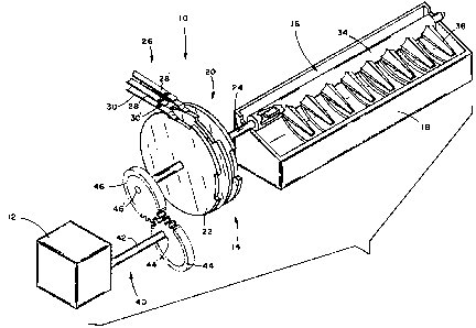
FIGURE 1 is an exploded, schematic view of an ice
making system.
FIGURES 2 and 3 are schematics showing two opeating
modes.
Referring now to the drawing, there is shown an ice
maker system 10 employing the features of the invention. The
ice maker system includes a motor 12 which drives a timing
mechanism 14, a harvest rake 16, and a liquid receptacle 18.
Motor 12 may be of the synchronous type and may include a gear
,.~1
:

~.2~ 4
train to provide a desired gear reduction. Timing mechanism 14 includes a cam
means 20 which includes a series of cams 22 carried on a camshaft 24, and
switch means 26. Switch means 26 includes a series of upper and lower
electrical contact blades 28 and 3G, one of which engages the cams. Rotation
of the cams causes the cams to ~pen and c70se electrical contacts 28' and 30'.
The opening and closing of the electrical contacts opens and closes electrical
circuits to control such functions as turning motor 12 on and off, controlling
a thermostat, etc. in a manner well known in the art. Harvest rake 16
includes a rod 34 and teeth 36 extending from the rod. The rod can be
connected to camshaft 24 by some suitable means or alternatively shaft 24 and
the rod could be of a one piece construction. Thus the h~rvest rake rotates
with camshaft 24.
In accordance with the present invention, a variable speed is imparted to
harvest rake 16. This is accomplished through coupling means 40 which couples
motor 12 to camshaft 24. Coupling means 40 includes a motor output shaft 42
and a pair of meshing gears 44 and 46. Gear 44 is fixedly carried on shaft 42
to be rotated therewith. Gear 46 is fixedly carried on camshaft 24 such that
the camshaft is rotated in accordance with the gear. As shown, each of the
gears 44 and 46 are non-circular. In the present embodiment, each of the
gears are elliptical with their centers of rotation being at one of the foci
44', 46' of their respective ellipse. The gears are programmed with respect
to each other such that a slower camshaft speed of rotation is generated when
harvest rake 16 is removing ice from the receptacle.
Referring to Figure 2, the operating mode of the gears are shown when
rake 16 is in the position when receptacle 18 is being filled with liqu;d.
The gears are shown at the position at or near the fastest speed being applied
to the rake. As shown, foci 44' is at its furthest point from the area A
where the gears mesh while foci 46' is at its closest point to area A.
In Figure 3, the operating mode of the gears are shown when rake 16 is
removing ice from receptacle 18. The gears are shown at or near the position

4_ 1 Z~3~f~
of slowest speed with highest torque being applied to the rake. As shown,
foci 44' is at its closest point to gear meshing area B while foci 46' is at
its furthest point from gear meshing area B.
Actual filling and removal may occur at positions slightly removed from
the positions shown in Figures 2 and 3; however, the benefits of the gearing
system are still realized.

Dessin représentatif
Une figure unique qui représente un dessin illustrant l'invention.
États administratifs

2024-08-01 : Dans le cadre de la transition vers les Brevets de nouvelle génération (BNG), la base de données sur les brevets canadiens (BDBC) contient désormais un Historique d'événement plus détaillé, qui reproduit le Journal des événements de notre nouvelle solution interne.

Veuillez noter que les événements débutant par « Inactive : » se réfèrent à des événements qui ne sont plus utilisés dans notre nouvelle solution interne.

Pour une meilleure compréhension de l'état de la demande ou brevet qui figure sur cette page, la rubrique Mise en garde , et les descriptions de Brevet , Historique d'événement , Taxes périodiques et Historique des paiements devraient être consultées.

Historique d'événement

Description Date
Inactive : Demande ad hoc documentée 1995-04-21
Le délai pour l'annulation est expiré 1994-10-21
Lettre envoyée 1994-04-21
Accordé par délivrance 1992-04-21

Historique d'abandonnement

Il n'y a pas d'historique d'abandonnement

Titulaires au dossier

Les titulaires actuels et antérieures au dossier sont affichés en ordre alphabétique.

Titulaires actuels au dossier
EMHART INDUSTRIES, INC.
EMERSON ELECTRIC CO.
Titulaires antérieures au dossier
RONALD E. COLE
Les propriétaires antérieurs qui ne figurent pas dans la liste des « Propriétaires au dossier » apparaîtront dans d'autres documents au dossier.
Documents

Pour visionner les fichiers sélectionnés, entrer le code reCAPTCHA :


Pour visualiser une image, cliquer sur un lien dans la colonne description du document. Pour télécharger l'image (les images), cliquer l'une ou plusieurs cases à cocher dans la première colonne et ensuite cliquer sur le bouton "Télécharger sélection en format PDF (archive Zip)" ou le bouton "Télécharger sélection (en un fichier PDF fusionné)".

Liste des documents de brevet publiés et non publiés sur la BDBC .

Si vous avez des difficultés à accéder au contenu, veuillez communiquer avec le Centre de services à la clientèle au 1-866-997-1936, ou envoyer un courriel au Centre de service à la clientèle de l'OPIC.


Description du
Document 
Date
(aaaa-mm-jj) 
Nombre de pages   Taille de l'image (Ko) 
Abrégé 1993-10-28 1 15
Page couverture 1993-10-28 1 9
Revendications 1993-10-28 2 43
Dessins 1993-10-28 2 30
Dessins représentatifs 2003-03-19 1 17
Description 1993-10-28 5 133