Note : Les descriptions sont présentées dans la langue officielle dans laquelle elles ont été soumises.
1~9899~
-- 1 --
4-i62 CVE-334
Tool For Cold Forging Tubular Members
Backaround
The cold forging of a tubular member into an annular
member such as a well hanger or a connector has been known
in the past. The cold forging has also been used to form a
tubular member into an annular connector in a remote loca-
tion, such as in a subsea pipeline repair. This is shown
in U. S. Patent Nos. 3,432,916 and 4,330,144. U. S. Patent
No. 4,662,663 discloses the use of pressure compensating
material between the two members being cold formed and such
material prevents the buildup of pressure which would
prevent the proper completion of the cold forming.
A tool previously used in this type of cold forging
process is shown in U. S. Patent No. 4,388,752. This tool
includes an alloy shaft having a shoulder on one end and a
ring surrounding the other end and a rubber tube expansion
element surrounding the shaft with annular nylon rings
engaging the ends of the rubber expansion element and alloy
rings supporting the exterior of each of the nylon rings.
The radial force is developed by the tool response to
longitudinal forced exerted on the expansion element. The
nylon rings are provided to prevent extrusion of the rubber
expansion element.
Other tools have been suggested which include a
resilient tubular member which is exposed to hydraulic
pressure internally and secured at its ends and is allowed
to exert outward radial forces to cold forge a tubular
member into the interior of an annular member.
Summarv
The present invention relates to an improved cold
forging tool to exert radial forces outwardly to form a
tubular member outwardly into an annular member. The
~b`-
lZ98996 5~845-346
-- 2 --
improved tool includes a central body having a shoulder means
on its exterior at both ends and support means connecting into
one end, a resilient sleeve surrounding said central body, a
passage through the central body to communicate between a
pressure supply means connected to the end of the body and the
interior of said resilient sleeve, a support ring surrounding
each end of said resilient sleeve and a segmented ring
positioned between the central expansion portion of said
resilient sleeve and each of said support rings and resilient
means retaining said segmented ring in surrounding relation~
ship to the ends of said resilient sleeve to prevent extrusion
of the resilient sleeve during the forming of the tubular
member.
In one aspect, the invention provides a tool for forging
tubular members comprising a cylindrical body having a passage
extending from its upDer end and exitinq at an intermediate
position on its outer surface, an upwardly facing shoulder
surrounding the lower portion of said body, a downwardly facing
upper shoulder surrounding the upper portion of said body, a
packer assembly surrounding said body and including a resilient
sleeve, an upper anti-extrusion ring surrounding the upper end
of said resilient sleeve below said downwardly facing upper
shoulder, a lower anti-extrusion ring surrounding the lower end
of said resilient sleeve above said upwardly facing shoulder,
each of said anti-extrusion rings including a plurality of
segments and means urging the seqments radially inward, and
1298996
65845-346
- 2a -
means for supplying fluid under pressure to the interior of
said resilient sleeve.
The present invention provides an improved durable tool
for cold forging a tubular member within an annular member and
which offers the advantage of preventing the extrusion of the
resilient sleeve even when forging high strength tubular steel
members, and the further advantage of not requiring that the
resilient sleeve be molded onto the tool during manufacture.
Brief Description of the Drawings
These and other objects and advantages are hereinafter
set forth and explained with reference to the drawings wherein:
FIGURE 1 is an elevation view partly in section of the
tool of the present invention having a tubular member to be
cold forged positioned in surrounding relationship thereto
and with the annular member into which the tubular member is to
be forged being connected to the tool and in surrounding
relationship to the tubular member and the tool.
A
12~8996
FIGURE 2 is a similar view of the improved packer
assembly used with the improved cold forging tool of the
present invention.
FIGURE 3 is another similar view of the tubular member
which has been cold forged into the annular member.
FIGURE 4 is a partial detail sectional view of the
improved tool in its relaxed position with the tubular
member and the annular member being shown.
FIGURE 5 is a sectional view taken along line 5 - 5 in
FIGURE 4.
FIGURE 6 is a partial detail sectional view of the
improved tool in its forming position with the tubular
member and the annular member being shown.
FIGURE 7 is a sectional view taken along line 7 - 7 in
FIGURE 6.
FIGURE 8 is a sectional view of another embodiment of
the improved tool of the present invention in which the
body or mandrel include the resilient packer integrally
molded therein.
Description of the Preferred Embodiment
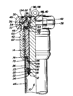
Improved cold forging tool 10 of the present inven-
tion, as best seen in FIGURE 1, includes the central body
or mandrel 12 with packer assembly 14 being positioned
25 therearound. Segments 16 have internal teeth 18 which
engage within grooves 2 0 around the lower exterior of body
12 and retainer ring 22 is secured to segments 16 by screws
24 to retain them in position within grooves 20 to provide
a lower body shoulder 25 in supporting relationship to
30 lower packer support ring 26. Annular recess 28 around the
interior of packer support ring 26 has seal ring 30
positioned therein to seal against the exterior of body
12. Packer assembly 14 is positioned between lower packer
support ring 26 and upper packer support ring 32. Upper
35 packer support ring 32 is positioned around the upper end
of body 12 in engagement with shoulder 34 formed on the
1298996
outwardly extending flange 36 of body 12. Annular recess
38 on upper packer support ring 32 has seal ring 40
positioned therein for sealing between the exterior of body
12 and the interior of support ring 32.
Annular member 42 into which tubular member 44 is to
be cold forged includes upper outer clamping shoulder 46
which is engaged by clamps 48 as is shoulder 50 on the
upper exterior of clamp ring 52 which is supported on
upwardly facing annular shoulder 54 of the flange portion
of tool 12. Upper packer support ring 32 engages down-
wardly facing shoulder 34 and also downwardly facing
shoulder 56 on clamp ring 52. Clamps 48 are held in
clamping engagement around shoulders 46 and 50 by
bolts 58.
As shown in FIGURE 1, tool 10, with annular member 42
supported thereon, is lowered into the desired position
with respect to tubular member 44. The upper end of
tubular member 44 is in engagement with the lower shoulder
60 on upper support ring 32. Resilient packer sleeve 62 is
mounted around mandrel 12 and has its upper and lower ends
positioned within recesses 64 and 66 between extensions 68
and 70 on packer support rings 32 and 26. As best seen in
FIGURE 2 recesses 64 and 66 are undercut to provide a
better engagement of the ends of packer sleeve 62.
Anti-extrusion rings 72 and 74 are positioned in surround-
ing relations to packer sleeve 62 immediately above lower
packer support ring 26 and immediately below upper packer
support ring 32. Anti-extrusion rings 72 and 74 are
substantially the same in construction and as best seen in
FIGURES 4 to 7, each includes a plurality of segments 76
having an outer annular recess 78 in which annular coil
spring 80 or other suitable resilient means which urges
segments 76 radially inwardly.
Annular member 42, as shown in FIGURE 3, which could
be a casing housing includes inner upper lightly threaded
or fine toothed surface 84, inner lower lightly threaded or
1298996
-- 5
fine toothed surface 86 and a plurality of internal grooves
88 having inwardly projecting lands 90 and 92 alternating
in position between the grooves 88 and lands 90 including
inwardly directed sharpened corners and projecting inwardly
a greater distance than the lands 92. The exterior surface
of annular member 42 is configured for the application
which it is to fill and may have external grooves and a
lower tapered seating surface 94.
In order to provide pressure to the interior of packer
sleeve 62, fluid under pressure is delivered to port 96 in
the upper end of body 12 which communicates with the
exterior of body 12 between seal rings 30 and 40. Fluid
pressure is then exerted on the interior of packer sleeve
62 and forces it radially outward with sufficient force to
cold forge tubular member 44 into tight gripping engagement
with the interior of annular member 42. Eye 98 is threaded
into the upper end of body 12 to raise and lower tool 10 in
a well bore.
Anti-extrusion ring 72 is illustrated in FIGURES 4 to
7 and is illustrative of ring 74 as well since both rings
have the same design. Segments 76 are formed by cutting
them from a metal ring having an external diameter which is
substantially the diameter of the interior of tubular
member 44 after it has been formed as shown in FIGURES 6
and 7. Segments 76 are cut preferably in a straight line
which is at an angle to a tangent at the point of entry of
the cut into the outer surface of the metal ring. It is
preferred that an angle of cut which is approximately forty
degrees to the tangent provides satisfactory segments. The
inside diameter of the metal ring before cutting of the
segments should be substantially smaller than the outer
diameters of support rings 26 and 32. The exterior surface
of the metal ring from which segments 76 are cut includes
an annular groove which forms recesses 78 in the exterior
surface of segments 76.
~2968996
When segments 76 are assembled into ring 72 in sur-
rounding relationship to the exterior end portion of packer
sleeve 62 in its relaxed position as shown in FIGURES 4 and
5, they are urged inward by coil spring 80, which is posi-
5 tioned within recesses 78 in the exterior surfaces of seg-
ments 76 to cause them to cant and have their inner tapered
ends engaging tightly into the exterior of packer sleeve 62
as best seen in FIGURE 5. When pressure is applied between
the exterior of body or mandrel 12 and the interior of
10 packer sleeve 62, packer sleeve 62 is moved radially
outward and anti-extrusion rings move outward therewith
until the exterior of segments 76 come into engagement with
the interior of tubular member 44 as shown in FIGURES 6 and
7. The exterior of segments 76 remain in engagement with
15 the interior of tubular member 44 and thus avoid the
occurrence of minor gaps between the exterior of rings 72
and 74 and the interior of tubular member 44. This
prevents the extrusion of packer sleeve 62 into gaps and
thereby protects the integrity of packer sleeve 62 so that
20 it will have a longer life. The use of the springs 80
provides a biasing force urging the segments inwardly and
when no pressure is being exerted on the packer sleeve 62,
they are fully retracted by the springs 80 so that they do
not interfere with the positioning of the forging tool 10
25 within the tubular member 44 that is to be formed. Also
the springs 80 resist the outward movement of packer sleeve
62 during forming to maintain each of segments 76 in
relatively the same radial position as all of the other
segments 76 so that they move outward uniformly until they
30 are in engagement with the interior of tubular member 44.
The other form of improved forging tool 100 of the present
invention is illustrated in FIGURE 8. Tool 100 includes
body or mandrel 102 which is supported on running string
104 and has packer 106 integrally molded therein into
35 recesses 108 and 110 with suitable anti-extrusion rings 112
and 114 being position in surrounding relationship to the
129899~
-- 7 --
ends of packer 106 and in abutting relationship to upper
shoulder 116 and lower shoulder 118 on body 102. Suitable
port, such as passageway 120, is provided in body 102
through which fluid under pressure is delivered to the
interior of packer 106 so that it may perform its forging
task as hereinafter described.
In FIGURE 8, tool 100 into the well bore with hous-
ing 122 with tool 100 supported thereon when in the desired
position with respect to tubular member 124 as shown, tool
100 is ready to be pressurized with fluid under pressure so
that packer 106 expands within tubular member 124 and
forces it into tight sealing and gripping engagement with
the interior recess 126 of housing 122. Anti-extrusion
rings 112 and 114 are moved radially outward with the
radial expansion of packer 106 while maintaining their
engagement with shoulders 116 and 118 and engage the
interior surface of tubular member 124 to prevent the
extrusion of packer 106 during the forging of tubular
member 124 into the interior of housing 122.
Recess 108 within body is shaped as shown with an
inwardly and upwardly extending portion 128 immediately
under shoulder 116 and its surface 130 is generally
cylindrical in shape at a position within upper anti-ex-
trusion ring 112. Surface 130 extends to tapered surface
132 which extends downwardly and outwardly to cylindrical
surface 134. Lower recess 110 is similar in shape to
recess 108 but is the mirror image thereof with portion 136
extending downwardly and inwardly immediately under
shoulder 118 and its surface 138 being qenerally cylindri-
cal i.n shape at a position within lower anti-extrusion ring
114. Surface 138 extends upward to tapered surface 140
which extends upwardly and outwardly to cylindrical surface
134. This shape allows packer 106 to be molded into
recesses 108 and 110 and with the installation of anti-ex-
trusion rings 112 and 114 and the connection of runningstring 104, tool 100 is ready for running and forging of
~298996
-- 8 --
tubular member 124 into recess 126 of housing 122. It is
believed that the shape of packer 106 within its recesses
108 and 110 together with anti-extrusion rings 112 and 114
causes packer 106 to be retained within its recesses 108
and 110 when fluid under pressure is delivered to the
interior of packer 106.
String 104 is connected to plate 142 which engages the
upper end of housing 122. This positions tool 100 in its
desired forging position with respect to housing recess
126. Also, a connection from a source of pressure fluid
(not shown) would extend to passageway 120 to provide the
forging pressure for the operation of tool 100.