Note : Les descriptions sont présentées dans la langue officielle dans laquelle elles ont été soumises.
lZ99867
--1--
This invention relates to a marker sleeve assembly for
holding tubular recoverable marker sleeves in appropriate
position for printing indicia on the marker sleeves then pro-
viding a convenient means for dispensing the printed marker
sleeves for use on wires or other objects to be identified
by the printed marker sleeves.
Heat recoverable marker sleeves have been used and
dispensed in various assemblies and configurations. U.S.
patent 4,032,010 to Evans discloses the use of heat reco-
verable marker sleeves on a fingered carrier suitable for
printing the marker sleeves in a typewriter or computer
printer. This assembly requires that the marker sleeves be
partially recovered onto the fingers of the carrier to hold
them on the carrier then after the marker sleeves are
printed they are removed, placed on the wire or substrate
and further recovered into final position.
U.S. patents 4,191,405 and 4,198,451 to Johnstun
disclose flattened heat shrinkable tubing as marker sleeves
which are laminated onto a carrier sheet. In one case
('405) they are laminated between carrier sheets and in the
other case ('451) the marker sleeves are laminated onto one
carrier sheet and the leading edges of the sleeves are
covered with a flap or layer of another material. Marker
sleeves acsembled in this fashion are difficult to register
for printing and difficult to remove from the sheets for use
after they are printed. These assemblies have multiple
layers which increase the thickness of materials which must
pass through the printer.
U.S. patents 4,361,230, 4,363,401, and 4,425,390 to
Downing et al., Savagian and Changani et al., respectively,
1~99867
disclose assemblies of marker sleeves made from sheets of
material which are bonded together at various seams and per-
forated for separation. The laminated and bonded sheets
themselves form the assembly and carrier means for the
marker sleeves. These types of marker sleeves suffer from
the disadvantage, however, that the welded edges and per-
forated seams either leave rough edges protruding from the
wires after the sleeve is recovered onto the wire (see
figure 4 of '230) or, if the sleeve is recovered suf-
ficiently to smooth out the edges, the seams frequently
break and the marker sleeve fails to remain on the wire.
Therefore, it is an object of the present invention to
provide a marker sleeve assembly that does not require par-
tial or preliminary recovery of the marker sleeves onto the
carrier means.
It is further an object of this invention to provide a
marker sleeve assembly that is easily adaptable to being
printed on platen fed or sprocket fed typewriters, computer
printers and the like without having undue multiple layers
of support sheets or materials.
It is a further object of this invention to provide a
marker sleeve assembly for flattened tubular recoverable
marker sleeves so that the tubular marker sleeves remain
sufficiently flattened during printing and return to their
smooth and uniform tubular shape when recovered on the wire
or other substrate thereby providing smooth tubular marker
sleeves without seams or rough edges.
It is yet a further object of this invention to provide
a marker sleeve assembly for flattened perforated tubular
lZ99867
recoverable marker sleeves so that the tubular marker
sleeves remain sufficiently flattened during printing and
return ~o their tubular shape when recovered on the wire
or other substrate thereby providing smooth tubular marker
sleeves without seams, though the ends of such sleeves will
not be smooth due to the perforations thereat.
One aspect of this invention comprises a marker sleeve
assembly comprising:
a series of flattened tubular recoverable marker sleeves
each having first and second opposing end portions; and
a first longitudinal carrier strip comprising an inner
edge portion and an outer edge portion wherein the inner
edge portion comprises means for securing thereto the
first end portion of each flattened tubular recoverable
marker sleeves such that the flattened marker sleeves
are held in a fixed transverse position extending
substantially perpendicularly from the carrier strip;
wherein the flattened tubular recoverable marker sleeves
are space apart vertically and wherein the inner edge
portion of the carrier strip engages the first end por-
tion~ of the flattened marker sleeves to thereby hold
the marker sleeves in their spaced apart positions.
A second longitudinal carrier strip may be provided to
secure the second end portions of the marker sleeves. The
inner edge of the carrier strip may comprise two layers
having adhesive means on the inside opposing faces thereof
to secure the end portions of the marker sleeves.
1299867
--4--
A preferred embodiment of the invention comprises a
marker sleeve assembly comprising:
a pair of longitudinal spaced apart carrier strips each
comprising an inner edge portion and an outer edge por-
tion wherein the inner edge portion of each carrier
strip comprises two layers having adhesive means on the
inside opposing facing surfaces thereof for securing
said surfaces to the outside surface of the end portions
of flattened tubular recoverable marker sleeves and for
securing portions of the opposing facing surfaces to
each other and wherein the two said layers are adapted
for receiving therebetween and in contact with the adhe-
sive means on the facing surfaces of the two layers the
end portions of flattened tubular recoverable marker
sleeves;
a series of flattened tubular recoverable marker sleeves
positioned transversely between said carrier strips
wherein the opposing end portions of the flattened
marker sleeves are positioned between the two said
layers of the inner edge portions of the two carrier
strips in contact with the adhesive means on the facing
surfaces of the two said layers of the carrier strip
whereby said adhesive means holds the flattened marker
sleeves in a fixed transverse position between the pair
of carrier strips; and
wherein the flattened tubular recoverable mar~er sleeves
are spaced apart vertically and wherein a portion of the
adhesive means on the opposing facing surfaces of the
lX99867
two layers of the inner edge portion of each carrier
strip alternately engages (a) the end portions of the
~lattened marker sleeves to thereby hold the marker
sleeves in their spaced apart positions and (b) the
adhesive means on the opposing facing layer of the inner
edge portion of the carrier strip in a sufficient area
of contact between the spaced apart flattened marker
sleeves to aid in holding the tubular marker sleeves.
In another additional aspect, this embodiment provides
the above marker sleeve assembly wherein the carrier strips
each comprise a strip of carrier material positioned outside
the end portions of the flattened tubular marker sleeves and
two opposing strips of adhesive coated tape disposed on
opposite sides of the inner portion of each carrier strip
whereby a portion of each tape engages the inner portion of
a carrier strip and a portion of each tape alternately enga-
ges (a) the end portions of the flattened tubular marker
sleeves and (b) the opposing adhesive coated surface of said
the opposing tape whereby said tapes contacting each other
in the spaces between the spaced apart marker sleeves to
thereby aid in holding the flattened tubular marker sleeves.
In an additional aspect, this embodiment further provi-
des the above marker sleeve assembly wherein the opposing
facing adhesive means areas contact each other along and
adjacent to the ends of the flattened tubular marker sleeves
to thereby further aid in holding the flattened tubular
marker sleeves in the desired position and configuration.
Figure 1 shows a perspective view of a preferred embodi-
ment of the marker sleeve assembly according to the present
invention.
~2~9867
--6--
Figure 2 shows a cross-section detail of the end por.ion
of a marker sleeve at section A-A of Figure 1.
Figure 3 shows a top view of another embodiment of the
marker sleeve assembly according to the present invention.
Figure 4 shows a perspective view of a further embodi-
ment of the marker sleeve assembly according to the present
invention.
The marker sleeve assembly of the present invention can
best be understood by reference to the drawings.
Figure 1 illustrates a perspective view of a preferred
embodiment of the marker sleeve assembly according to the
present invention which comprises carrier strips 1, 2 having
sprocket holes 3 in the outer portions of carrier strips 1,
2. The inner portions 4, 5 of carrier strips 1, 2, respec-
tively, comprise two layers each having adhesive means on
the inside opposing facing surfaces thereof. The flattened
tubular marker sleeves 6 are positioned with the end por-
tions of the marker sleeves between said opposing facing
layers of the inner portions of the carrier strips and are
held in position by the adhesive means on the inside
opposing facing surfaces. The adhesive means on each layer
of the inner portion of each carrier strip alternately enga-
ges the opposing adhesive means on the opposite layer in
regions 7 and engage the outside surface of the end portions
of the marker sleeves in regions 8. In one preferred con-
figuration the adhesive means on each layer also engages the
opposing facing adhesive means along and adjacent to the
ends of the marker sleeves in regions 9. The distance bet-
~299~367
--7--
ween the marker sleeves should be sufficient to allow suf-
ficient area in regions 7 for the opposing adhesive means to
engage each other to hold the opposing layers together.
Consequently, the minimum distance between the marker
sleeves will be determined by the flexibility of the carrier
strip, the effectiveness and bonding power of the adhesive
means to engage and hold the opposing adhesive means, the
degree of bonding desired in regions 7 and other factors
that will be apparent to one skilled in the art. Otherwise,
the distance between marker sleeves can be increased and
adjusted as desired for printing alignment purposes,
packaging purposes, and the like. Regions 7 where the
opposing adhesive means engage each other can be of any
length provided that the minimum length and surface area is
provided to meet the requirements stated above. In one pre-
ferred embodiment it is desired that the top or leading edge
10 of each flattened tubular marker sleeve be aligned with a
pair of sprocket holes 3 in the two carrier sleeves to aid
in programming computer printers for proper alignment of
printing indicia on the marker sleeves.
It should be noted that flattened tubular marker sleeves
tend not to remain in the flattened condition but tend to
return to their tubular configuration as illustrated at
cross-section 11 of marker sleeve 12. Tubular marker
sleeves can be flattened with sufficient heat and pressure
so that they do tend to remain in the flattened con-
figuration. During this process a distinctive crease or
edge portion may be imparted to a tubular marker sleeve.
Such a crease tends to help maintain flatness of the tubing.
One of the advantages of the marker sleeve assembly of this
~299867
embodiment of the invention is that the opposing layers in
the inner portions of each carrier strip which are engaged
the opposing layer in region 7 assist in holding the flat-
tened tubular marker sleeves in their flattened condition
until they can be printed and removed from the marker sleeve
assembly of this invention.
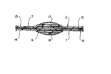
Figure 2 is a section view A-A in Figure 1 showing the
end view of a flattened tubular marker sleeve 6 the end por-
tion of which is held between opposing layers 13, 14 of
carrier strip 2 and is secured in position by adhesive
layers 15, 16 on opposing surfaces of layers 13, 14. Figure
2 also illustrates that in the region between the two
carrier strips 1, 2 marker sleeve 6 may not remain comple-
tely in its flattened condition and may assume an oval or
elliptical shape as indicated by surfaces 17, 18 in Figure
2. However, it is to be noted that the sleeves preferably
maintain their flattened configuration. It should also be
noted that the adhesive surfaces 15, 16 are bonded together
in region 7.
Figure 3 illustrates another embodiment of the marker
sleeve assembly of the present invention wherein carrier
strips 31, 32 are separate strips and the adhesive means is
provided by opposing tapes 33, 34 having adhesive surfaces
to engage carrier strip 31 and the end portions of marker
sleeves 36. Opposing adhesive tapes 33, 34 bond to each
other in regions 37 and bond to the opposite sides of the
end portions of flattened tubular marker sleeves in regions
39. Tapes 33, 34 engage the carrier strip 31 along the
inner portion of carrier strip 31 and along its entire
~29~867
g
length. Adhesive strips 33, 34 can be segmented or per-
forated or discontinuous which in some cases will aid in the
ease of removal of the marker sleeves from the marker sleeve
assembly provided that sufficient bonding in regions 37, 39
are achieved by the lengths of tapes 33, 34 which are used.
In normal configuration the inner edge of carrier strips
31, 32 are adjacent to the ends of the flattened tubular
marker sleeves and the adhesive tapes 33, 34 cover the areas
of each as explained above. However, in some configurations
it may be desirable to leave a space in region 38 between
the inner edge of carrier strip 31 and the end of marker
sleeve 36 to allow the opposing adhesive surfaces of
opposing tapes 33, 34 to bond to each other along and adja-
cent to the ends of marker sleeves 36 to further aid in
holding the flattened tubular marker sleeves 36 in the
desired position and aid in holding the flattened marker
sleeves in the desired flattened configuration.
Figure 4 illustrates a perspective view of a further
embodiment of the invention. In Figure 4, a single carrier
strip 40 comprises inner edge portion 42 and outer edge por-
tion 44. Flattened tubular recoverable sleeves 46 are
secured to the inner edge portion 44 of carrier strip 40 by
means of an adhesive on the surface of the inner edge sur-
face. The second end portion of the flattened sleeves in
this embodiment are free. If desired, a second carrier
strip (not shown) similar to the first can be positioned to
secure the second end portions of the marker sleeves. The
securing means on the inner edge portion of one or both of
the carrier strips may comprise two layers with adhesive on
~299867
--10--
the facing surfaces as described above with reference to
Figs. 1 and 3.
In another embodiment of the invention, a single carrier
strip may be provided with a center portion and two outer
edge portions, each of which is provided with means to
secure the first end portions marker sleeves thereto, as
described above. The center portion may be provided with
sprocket holes, if desired. The means for securing the
sleeves may be adhesive means along the outer edge portions
or preferably, as described above, the edge portions may
comprise two ~ayers with adhesive means on the inside
opposing facing surfaces thereof. Additional carrier strips
may be provided to secure the second end portions of the
marker sleeves, if desired.
The above embodiments are illustrations of the marker
sleeve assembly of the present invention. Other embodiments
will be apparent to one skilled in the art. The selection
of materials for carrying out embodiments of the present
invention will likewise be apparent to one skilled in the
art depending on the size and configuration of the marker
sleeve assembly of this invention.