Sélection de la langue

Search

Sommaire du brevet 1300045 

Énoncé de désistement de responsabilité concernant l'information provenant de tiers

Une partie des informations de ce site Web a été fournie par des sources externes. Le gouvernement du Canada n'assume aucune responsabilité concernant la précision, l'actualité ou la fiabilité des informations fournies par les sources externes. Les utilisateurs qui désirent employer cette information devraient consulter directement la source des informations. Le contenu fourni par les sources externes n'est pas assujetti aux exigences sur les langues officielles, la protection des renseignements personnels et l'accessibilité.

Disponibilité de l'Abrégé et des Revendications

L'apparition de différences dans le texte et l'image des Revendications et de l'Abrégé dépend du moment auquel le document est publié. Les textes des Revendications et de l'Abrégé sont affichés :

  • lorsque la demande peut être examinée par le public;
  • lorsque le brevet est émis (délivrance).
(12) Brevet: (11) CA 1300045
(21) Numéro de la demande: 1300045
(54) Titre français: FREIN A DISQUE ELECTRIQUE
(54) Titre anglais: ELECTRICALLY ACTUATED DISC BRAKE
Statut: Périmé et au-delà du délai pour l’annulation
Données bibliographiques
(51) Classification internationale des brevets (CIB):
  • F16D 65/16 (2006.01)
  • B60T 13/74 (2006.01)
  • F16D 55/224 (2006.01)
  • F16D 63/00 (2006.01)
  • F16D 65/14 (2006.01)
  • F16D 65/18 (2006.01)
(72) Inventeurs :
  • TAIG, ALISTAIR GORDON (Etats-Unis d'Amérique)
(73) Titulaires :
  • ALLIED-SIGNAL INC.
(71) Demandeurs :
(74) Agent: MACRAE & CO.
(74) Co-agent:
(45) Délivré: 1992-05-05
(22) Date de dépôt: 1988-04-26
Licence disponible: S.O.
Cédé au domaine public: S.O.
(25) Langue des documents déposés: Anglais

Traité de coopération en matière de brevets (PCT): Non

(30) Données de priorité de la demande:
Numéro de la demande Pays / territoire Date
105,756 (Etats-Unis d'Amérique) 1987-10-07

Abrégés

Abrégé anglais


ELECTRICALLY ACTUATED DISC BRAKE
ABSTRACT OF THE DISCLOSURE
The electrically actuated disc brake (10)
comprises a caliper (12) having a bore (16) receiving
therein an actuating mechanism (90), and an electric
motor (40)attached to the caliper housing (12). The
actuating mechanism (90) comprises a planetary gear
mechanism (50) which includes a sun gear (52), planetary
gears (54), and a pair of ring gears (70, 80). An actua-
tor sleeve (68) is disposed about the ring gears (70, 80)
and contains a helical groove (69) disposed opposite a
complementary-shaped helical groove (89) in a rotatable
ring gear (80). The helical grooves (69, 89) receive
therebetween a bearing mechanism (85) biased by a spring
(87) toward a fixed stop (86) located within the helical
grooves (69, 89). Operation of the electric motor (40)
effects rotation of the rotatable ring gear (80) and
axial displacement of the actuator sleeve (68) into en-
gagement with a thrust pad (96) located adjacent one of
the friction elements (18) so that the caliper (12), by
reaction, displaces the other friction element (20) into
engagement with the rotor (22).

Revendications

Note : Les revendications sont présentées dans la langue officielle dans laquelle elles ont été soumises.


THE EMBODIMENTS OF THE INVENTION IN WHICH AN EXCLUSIVE
PROPERTY OR PRIVILEGE IS CLAIMED ARE DEFINED AS FOLLOWS:
1. A disc brake operated by electric motor means,
comprising a caliper having a bore aligned with the motor
means, the bore having an actuating mechanism disposed
therein, the actuating mechanism and caliper actuable to
displace a pair of friction elements into engagement with
a rotor, the actuating mechanism comprising a planetary
gear assembly disposed within said bore and comprising a
sun gear, a carrier, planetary gears, and a pair of ring
gears, the electric motor means coupled with the sun gear
which drives the planetary gears, one ring gear connected
with the caliper and the other ring gear rotatable by said
planetary gears, an actuator sleeve disposed about the
other ring gear, bearing means disposed between said other
ring gear and actuator sleeve, a spherical abutment washer
disposed adjacent said one ring gear, the spherical abut-
ment washer having a spherical surface mating with a com-
plementary-shaped surface formed on the one ring gear to
permit axial misalignment of the actuating mechanism rela-
tive to said caliper, operation of said electric motor
means effecting rotation of the other ring gear and dis-
placemnt of the bearing means which effects axial displace-
ment of the actuator sleeve to cause one of said friction
elements to be displaced and the caliper, by reaction,
displacing the other friction element into engagement with
the rotor.
2. The disc brake in accordance with claim 1, wherein
the spherical abutment washer includes an opening receiving

therein a key, the key anchoring the spherical abutment
washer and one ring gear relative to the caliper.
3. The disc brake in accordance with claim 1,
wherein the caliper includes sealing means disposed adja-
cent an opening of said bore, the sealing means engaging
an outer surface of said actuator sleeve.
4. The disc brake in accordance with claim 1, further
comprising thrust bearing means disposed between said
ring gears.
5. The disc brake in accordance with claim 1, fur-
ther comprising a thrust pad disposed between said actuator
sleeve and the one friction element.
6. The disc brake in accordance with claim 5,
wherein the thrust pad includes connection means connecting
the thrust pad nonrotatably with said one friction element.
7. The disc brake in accordance with claim 1, wherein
the other ring gear and the actuator sleeve each include
circumferential grooves therein, the bearing means dis-
posed in said circumferential grooves.
8. A disc brake operated by electric motor means,
comprising a caliper having a bore aligned with the motor
means, the bore having an actuating mechanism disposed
therein, the actuating mechanism and caliper actuatable
to displace a pair of friction elements into engagment
with a rotor, the actuating mechanism comprising a planet-
ary gear assembly disposed within said bore and comprising

a sun gear, a carrier, planetary gears, and a pair of ring
gears, the electric motor means coupled with the sun gear
which drives the planetary gears, one ring gear connected
with the caliper and the other ring gear rotatable by said
planetary gears, an actuator sleeve disposed about the
other ring gear, bearing means disposed between said other
ring gear and actuator sleeve, a face plate disposed between
said one ring gear and an end of said bore, the one ring
gear including, along a diameter thereof, cylindrical pro-
trusion means received slidably within cylindrical recess
means formed in the plate, so that said actuating mechanism
may axially misalign relative to the caliper, operation of
said electric motor means effecting rotation of the other
ring gear and displacement of the bearing means which effects
axial displacement of the actuator sleeve to cause one of
said friction elements to be displaced and the caliper, by
reaction, displacing the other friction element into engage-
ment with the rotor.
9. The disc brake in accordance with claim 8, wherein
the face plate includes a plurality of axial teeth which
are received within complementary-shaped openings in the
one ring gear, so that the one ring gear is positioned non-
rotatably relative to the caliper.
10. A disc brake actuated by motor means, comprising
a caliper having a bore with an actuating mechanism dis-
posed therein, the actuating mechanism and caliper actuatable
to displace a pair of friction elements into engagement
with a rotor, the actuating mechanism comprising a planetary

gear assembly disposed within said bore and including a
sun gear, planetary gears, and a pair of ring gears, the
motor means coupled with said sun gear which drives the
planetary gears, one ring gear connected with said cali-
per and the other ring gear rotatable by said planetary
gears, an actuator sleeve disposed about said other ring
gear, the actuator sleeve and other ring gear including
complementary-shaped grooves therein, bearing means dis-
posed within the grooves between the actuator sleeve and
other ring gear, and a plate disposed between said one ring
gear and an end of said bore, the plate including cylindri-
cal recess means receiving slidably therein cylindrical
protrusion means extending, along a diameter thereof, from
the one ring gear so that the actuating mechanism may
axially misalign relative to the caliper, operation of said
motor means causing rotation of said other ring gear and
operative displacement of said actuator sleeve to cause dis-
placement of one of said friction elements so that the
caliper, by reaction, displaces the other friction element
into engagement with said rotor.
11. A disc brake actuated by an electric motor, com-
prising a caliper having a bore with an actuating mechanism
disposed therein, the actuating mechanism and caliper actu-
atable to displace a pair of friction elements into engage-
ment with a rotor, the actuating mechanism comprising a
planetary gear assembly disposed within said bore and in-
cluding a sun gear, planetary gears, and a pair of ring
gears, the electric motor coupled with said sun gear which
drives the planetary gears, one ring gear connected with

said caliper and the other ring gear rotatable by said
planetary gears, an actuator sleeve disposed about said
other ring gear, the actuator sleeve and other ring gear
including therein complementary-shaped grooves, and
bearing means disposed within the grooves between the
actuator sleeve and other ring gear, the bearing means
comprising a plurality of balls biased by resilient means
disposed within the grooves, the grooves comprising heli-
cal grooves and the resilient means comprising a spring
which biases the plurality of balls toward engagement
with a fixed stop disposed within said grooves, and the
actuating mechanism further comprising a spherical abutment
washer disposed between said one ring gear and an end of
said bore, and key means received by said spherical abut-
ment washer and one ring gear so as to dispose nonrotatably
the one ring gear relative to the caliper, operation of
said motor causing rotation of said other ring gear and
operative displacement of said actuator sleeve to cause dis-
placement of one of said friction elements so -that the
caliper, by reaction, displaces the other friction element
into engagement with said rotor.
12. The disc brake in accordance with claim 11, fur-
ther comprising a sealing ring disposed adjacent an open-
ing of said bore and engaging an outer surface of said
actuator sleeve.
13. The disc brake in accordance with claim 12, fur-
ther comprising thrust means disposed between said ring
gears.
11

Description

Note : Les descriptions sont présentées dans la langue officielle dans laquelle elles ont été soumises.

~L31VO~
ELECTRICALLY ACTUATED DISC BRAKE
This invention relates generally to a disc brake
that may be operated by a motor connected with a planetary
gear mechanism.
Dlsc brakes have been utilized for many years
in passenger cars, heavy duty trucks, and aircraft. Because
of the increasing emphasis on reducing the weight of vehi-
cles and simplifying the components thereof, it is desir-
able to develop a braking system that is operated electric-
ally. Such a braking system must be highly reliable, costeffective, and practical within the packaging constraints
of the particular vehicle. The present invention provides
a disc brake that may be operated by an electric motor, or
other rotary operating motor mechanisms, connected with a
planetary gear mechanism. The disc brake may be operated
to provide service brake application or to provide a park-
ing brake application. The resul.t is a highly reliable,
low cost, electrically operated disc brake which will fit
readily within the packaging constraints of several
vehicles.
The present invention comprises a disc brake
operated by electric motor means. A caliper has a bore
aligned with the motor means, the bore having an actuating
mechanism disposed therein, the actuating mechanism and
caliper being actuatable to displace a pair of friction
elements into engagement with a rotor. The actuating mech-
anism comprises a planetary gear assembly disposed within
the bore and includes a sun gear, a carrier, planetary gears,
and a pair of ring gears. The electric motor means are
r
~i A~
SP ~l'' '

~ ~2~ ~ S
coupled wlth the sun gear which drives the planetary gears,
one ring gear being fixed to the caliper and the other ring
gear being rotatable by the planetary gears. An actuator
sleeve is disposed about the other ring gear, and bearing
means are disposed between the other ring gear and actuator
sleeve, so that operation of the electric motor means e~fects
rotation of the other ring gear and displacement of -the
bearing means which effects axial displacement of the actua-
. tor sleeve to cause one of the friction elements to be ais-
placed and the caliper, by reaction, displacing the other
frlction element into engagement with the rotor.
The invention described below with reference to
the drawings which illustrate embodiments in which:
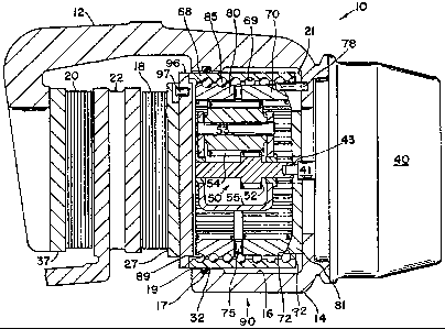
Figure 1 is a section view of a first embodimenti
Figure 2 is a partial view of the other ring gear
and bearing mechanism;
~ igure 3 is a seciton view of a second embodiment;
and
Figure 4 is an isometric view of the nonrotatable
ring gear and plate of Figure 3.
: The disc brake of the present invention is refer-
enced generally by numeral lO in Figure l. Disc brake 10
; ~ comprises a brake that is operated by motor means 40.
Motor means 40 may compr1se an electric motor or other
motor mechanisms that provide a rotary output via shaft 41
and coupling 43. Disc brake 10 includes a caliper 12 hav-
ing a caliper housing 14 with a bore 16. Caliper 12 extends
over a ~air of friction elements 18 and 20 which may be
displaced toward one another in order to brake a rotor 22.
sp

~300~gL5
-- 3 --
The bore 16 comprises a groove 17 adjacent opening 19, and
bore end 21. Seal 32 is disposed within groove 17. Located
within bore 16 is an actuating mechanism referenced generally
by numeral 90. Actuating mechanism 90 comprises a planetary
gear assembly 50 which includes a sun gear 52, three planet-
ary gears 54 (the other two not shown in the section view),
a carrier 55, pins 53 which carry the planetary gears, two
ring gears 70, 80, and thrust bearings 75. Each ring gear
has internal teeth, and ring gear 80 is rotatable but has
fewer teeth than ring gear 70 which is operatively coupled
with caliper housing 14. The planetary gear assembly 50 com-
prises the planetary gear assembly disclosed in commonly
owned Patent No. 4,793,447 entitled "ELECTRICALLY OPERATED
DISC BRAKE". Because the two ring gears 70 and 80 have dif-
ferent numbers of teeth, the planetary gear assembly 50 has
a high reduction ratio, as disclosed in U.S. Patent No.
4,793,447. Ring gear 70 is rotatably fixed relative to cali-
per housing 14 by means of a key 78 which is received within
complementary-shaped recesses in the caliper housing and
ring gear 70. Located between ring gear 70 and bore end 21
is a spherical abutment washer 81 which has a spherical
surface 92 that mates slidingly with spherical surface 72 of
ring gear 70. The spherical abutment washer has a recess
opening which receives key 78 so that it also is nonrotatably
fixed relative to caliper housing 14. However, because
rotatably fixed ring gear 70 may slide relative to the abut-
ment washer 81, the actuating mechanism 90 may center or
axially misalign itself relative to the caliper housing 14.
Located about the ring gears is an actuator sleeve 68 having
sp ~

-- 4 --
disposed therein a helical groove 69. Rotatable ring gear
80 has a helical groove 89, and a plurality of bearing balls
85 are disposed between the helical grooves 69, 89. As
illustrated in Figure 2, the helical groove 89 receives the
plurality of balls 85 which engage a fixed stop 86 disposed
in groove 89. The fixed stop 86 may be located in either of
the helical grooves 89 or 69. A spring 87 also engages a
fixed stop (not shown) disposed within either of the grooves
and biases the balls 85 toward the fixed stop 86. The balls
do not recirculate but are held against the fixed stop 86
when there is no load applied to the bearing balls. The
spring 87 allows a limited movement of the bearing balls 86
in the helical groove 89 when the gear 80 is rotated and
advances axially the actuator sleeve 68.
Actuator sleeve 68 engages a thrust pad 96 which
bears against the backing plate 27 of i.nner friction ele-
ment 18, pad 96 restrained from rotating by a pin 97 or by
any other alternative keying mechanism.
In operation, mechanism 90 begins from the rest
position shown in Figure 1 wherein friction elements 18, 20
are disposed clear of rotor 22. When the driver applies the
vehicle brakes, a force-sensitive signal from the brake
pedal is sent to a controller (not shown) which conditlons
and amplifies the output to supply current to the motor 40.
Rotation of motor shaft 41 and sun gear 52 causes ring gear
80 to rotate at a greatly reduced speed so that ball bearings
85 advance actuator sleeve 68 against thrust pad 96 and dis-
place friction elements 18 and 20 into engagement with
rotor 22. Axial displacement of element 18 causes caliper
sp: ,

s
12, by reaction, to displace backing plate 37 and pad friction
element 20 into engagement with rotor. Increased brake pedal
force increases the current in motor 40 and advances further
actuator sleeve 68. When the input signal is released, bear-
ing balls 85 are reversible via spring 87, and this causes
ring gear 80 to reverse rotation until only a small load re-
mains on the friction elements. The controller senses release
of an applied load and a small reverse current is applied to
motor 40 for a predetermined short period of time so that
mechanism 90 retracts positively actuator sleeve 68. As a
result, bearing balls 85 are in an unloaded condition and
spring 87 biases them to a return position against fixed stop
86.
The electrically actuated disc brake provides sev-
eral distinct advantages. The electric brake is self-powered
and needs no pumps or special force multiplying mechanisms.
The conventional master cylinder contained in braking systems
is eliminated, and all brakes can be independent of one
another which provides distinct safety advantages. The brake
mechanism provides electrically actuated brakes, positive
brake retraction in order to eliminate drag of the friction
elements on the rotor, and the mechanism is self adjusting
in order to compensate for wear of the friction elements.
The electric signals communicated to each disc brake can be
modified easily in conjunction with a vehicle anti-skid
system, and trailer brakes need only electrical connections.
Figure 3 shows an alternative construction for
providing self-alignment or axial misalignment of mechanism
90 relative to caliper 12. Rotatably fixed ring gear 70
sp: ~y C C

~L3~
-- 6 --
includes a pair of cylindrical protrusions disposed opposite
one another along a diameter of gear 70. Protrusions 73 are
shaped complementary to cylindrical recesses 83 formed in
plate 82. Plate 82 includes a plurality of teeth 84 (see
Figure 4) which are received within teeth grooves 74 of ring
gear 70. Plate 82 is fixed to caliper housing 14. The teeth
84 prevent rotation of ring gear 70 relative to caliper 12.
Cylindrical protrusions 73 have their center-line close to
the plane of rotation containing seal 32 in order to facili-
tate rotation of actuator mechanism 90 for alignment purposes,which includes axial misalignment of mechanism 90 relative
to caliper 12.
Other provisions of the invention or variations
will become apparent to those skilled in the art and will
suggest themselves from the specific applications of the in-
vention. It is intended that such variations and revisions
of the invention, as reasonably to be expected on the part
of those skilled in the art, to suit individual design prefer-
ence and which incorporate the herein disclosed principles,
will be included within the scope of the following claims
as equivalents thereof.
Sp: ~C(

Dessin représentatif
Une figure unique qui représente un dessin illustrant l'invention.
États administratifs

2024-08-01 : Dans le cadre de la transition vers les Brevets de nouvelle génération (BNG), la base de données sur les brevets canadiens (BDBC) contient désormais un Historique d'événement plus détaillé, qui reproduit le Journal des événements de notre nouvelle solution interne.

Veuillez noter que les événements débutant par « Inactive : » se réfèrent à des événements qui ne sont plus utilisés dans notre nouvelle solution interne.

Pour une meilleure compréhension de l'état de la demande ou brevet qui figure sur cette page, la rubrique Mise en garde , et les descriptions de Brevet , Historique d'événement , Taxes périodiques et Historique des paiements devraient être consultées.

Historique d'événement

Description Date
Inactive : CIB désactivée 2012-01-07
Inactive : CIB expirée 2012-01-01
Inactive : CIB du SCB 2012-01-01
Inactive : CIB de MCD 2006-03-11
Inactive : Demande ad hoc documentée 1997-05-05
Le délai pour l'annulation est expiré 1997-05-05
Lettre envoyée 1996-05-06
Accordé par délivrance 1992-05-05

Historique d'abandonnement

Il n'y a pas d'historique d'abandonnement

Titulaires au dossier

Les titulaires actuels et antérieures au dossier sont affichés en ordre alphabétique.

Titulaires actuels au dossier
ALLIED-SIGNAL INC.
Titulaires antérieures au dossier
ALISTAIR GORDON TAIG
Les propriétaires antérieurs qui ne figurent pas dans la liste des « Propriétaires au dossier » apparaîtront dans d'autres documents au dossier.
Documents

Pour visionner les fichiers sélectionnés, entrer le code reCAPTCHA :


Pour visualiser une image, cliquer sur un lien dans la colonne description du document. Pour télécharger l'image (les images), cliquer l'une ou plusieurs cases à cocher dans la première colonne et ensuite cliquer sur le bouton "Télécharger sélection en format PDF (archive Zip)" ou le bouton "Télécharger sélection (en un fichier PDF fusionné)".

Liste des documents de brevet publiés et non publiés sur la BDBC .

Si vous avez des difficultés à accéder au contenu, veuillez communiquer avec le Centre de services à la clientèle au 1-866-997-1936, ou envoyer un courriel au Centre de service à la clientèle de l'OPIC.


Description du
Document 
Date
(aaaa-mm-jj) 
Nombre de pages   Taille de l'image (Ko) 
Revendications 1993-10-28 5 184
Abrégé 1993-10-28 1 46
Page couverture 1993-10-28 1 12
Dessins 1993-10-28 2 75
Dessins représentatifs 2003-03-19 1 29
Description 1993-10-28 6 217
Taxes 1995-04-18 1 101
Taxes 1994-04-18 1 68