Note : Les descriptions sont présentées dans la langue officielle dans laquelle elles ont été soumises.
~3~
SYPHON ASSEMBL~, PACKAGE, HEAD, METHOD, FIL1ING
APPARATUS AND FILLING PE~OCESS
This is a divisional of Canadian Patent Application
Serial No. 480,991 filed May 8, 1985.
BACKG~OUND OF THE INVENTION
1. Field of the Invention
This invention relates to the storage and dispensing of
water or flavored beverages under gas pressure of between 90 and
150 psi (10 atmospheres). Such products are commonly known as
syphon seltzer water, as distinguished from present day bottled
sparkling waters or lightly carbonated flavored beverages which
are charged to pressures of 50 to 60 psi (3 to 4 atmospheres).
For further purposes of comparison, champagne is under about 6 to
7 atmospheres o~ pressure. This invention further relates to a
simplified syphon asse~bly for use to dispense liquids stored in
a container under pressure and to a package incorporating the
syphon assembly. This invention also relates to an improved
closure especially configured for fabrication in a single molding
step. More particularly, it relates to such a closure that is
tamper-resistant prior to actuation by an end user. In another
aspect this invention relates to a modified form of a seltzer
bottle filling apparatus and to a process for filling a seltzer
bottle having a detachable head with the head det~ched. More
particularly, it relates to such an apparatus and process in
which such a seltzer bottle is filled through a valve mechanism
that remains on the bottle.
2. Description of the Prior Art
Although the syphon seltzer water industry was a giant
at the tuxn of the century and reached its zenith in the 1920s,
today it is remembered mostly by the classic syphon seltzer
bottle which was used as a comedy prop by the Marx Brothers and
The Three Stooges to squirt each other in wild water fights. The
New York area alone at one time had 2,000 syphon seltzer
companies. Today there are about a dozen seltzer bottlers in the
United States. There are only two syphon seltzer bottlers west
-- 1 --
13~5~9
of Chicago.
The syphon seltzer industry died after World War II and
remains as a nostalgic, marginally profitable local business
carried on by only a handful of energetic young folk who hand
fill and hand deliver the old-fashioned syphon seltzer water to a
fiercely loyal group of purists who want nothing more and nothing
less than thrice-filtered water and carbon dioxide. There are no
salts; no flavors; no preservatives, a trio that is sweet music
to the palates of the health conscious.
Syphon seltzer water, up until now, however, because of
the use of high pressures in glass bottles was a victim of
several factors: ~1) the high cost of products liability
insurance; a heavy glass bottle exploding under a pressure of 150
psi can inflict awesome damage; (2) the high cost of heavy glass
bottle manufacture; (3) the high cost of tin, rubber, an~ brass
used in the manufacture of the pewter heads and valves; (6) the
high cost of bottle delivery and pick-up of the heavy, fragile
bottles; ~7) the high cost and difficulty in sanitizing the
returned bottles, and especially the returned heads and valves;
and ultimately (8) the switch by the mass market to lightly
carbonated flavored drinks in disposable cans and thin bottles.
The syphon seltzer water industry died, not for a good product,
but for the variety of reasons set forth above which related to
its storage, distribution and dispensing problems.
A brief background, therefore, of the selt~er industry
and the syphon seltzer container is necessary to an understanding
of the dramatic change this invention brings to an industry which
has essentially stood still for the last sixty years.
Mineral waters with light natural carbonation were
enjoyed by earliest man; the Romans knew about them but used the
water more for bathing than drinking, witness Bath. The Germans
and the French considered the mineral waters to have curative
powers and they live today in such industries as Vichy, and
Perrier. Of course, the mineral waters from the early spas could
not be transported very far, because heat and lack of
pressurized vessels took its toll on the taste and effervescent
quality of the water. In 1772, a British scientist, Joseph
-- 2
S&~
Priestly, better known for his discovery oE oxygen, succeeded in
producing artificially carbonated water. He made it in barrels
and the race for a container was on. The British Na~y mixed the
carbonated water with lime juice and later the practice was
adopted through the Royal Navy to prevent the sailors from
getting scurvy from their vitamin-deficient diet; hence the term
"Limeys". Nicholas Paul of Geneva is credited with starting to
manufacture imitation spa waters in bulk in 17B9 and one of his
partners, Jacob Schweppe, four years later started making soda
water.
The manufacture of carbonated water in the United
States began in the early part of the 19th Century. A patent was
granted in 1810 for saturating water with "fixed air."
INV~NTION OF THE SYPHON BOTTLE
Charles Plinth is credited as being the first to
preserve "aerated waters" in a reservoir which would deliver a
portion of its contents at different times. HiS patent on a
Regency portable fountain in 1813 was identical in construction
with the fountains then commonly used in which the motive force
was compressed atmospheric air. Plinth substituted carbonic acid
gas for air in his apparatus. It consisted of a vessel with a
tube passing from an opening in the top almost to the bottom; the
upper part of the tube was furnished with a stop-cock and
delivery tube, from which the water was drawn off under pressure
of the carbonic acid gas. -
Deleuze and Dutillet, Paris jewellers, who apparentlywere adverse to consuming an entire bottle of champagne at one
sitting were granted a patent in 1829 on a "siphon champenois"
which consisted of a hollow corkscrew which was passed through
the cork into the bottle. The upper part of the screw terminated
in a vertical tube bearing a nearly horizontal spout. A lever
operated a valve, which when opened and the bottle was tlpped,
gave exit to the champagne under pressure of the conta.ined gas.
The forerunner of the present day syphon seltzer bottle
was patented in 1837 by Antoine Perpigna of Paris, France. The
vase was made of metal, glass, china or stoneware and the head of
the syphon was hollow and contained a piston, pressed down by a
-- 3
~301~
spring into close contact with the upper end of the tube passing
to the bottom of the vase. The method of attaching these early
head mechanisms to the bottle or vessel is unknown to applicant
but it appears from the articles that there was some sort of
external collar mechanism, or perhaps the head mechanism which
protruded above the bottle was adhesively affixed to the bottle.
The split collar mechanism which is unive-rsally adopted
and is still in use today was invented in about 1855 by the Comte
de Fontainemoreau and George Rogers. They used a bottle made
with a groove around the outer wall of the neck into which was
fitted a ring of metal divided into two segments which formed a
shoulder for securing a screwed collar.
The problem with the Rogers mechanism and virtually
every mechanism for syphon seltzer water to the present day is
the fact that the head mechanism, containing the valve and spout,
must be assembled on the bottle before filling. The bottle is
filled through the head mechanism and the entire assembly of head
and filled water bottle must be transported from the factory,
through the distribution chain, to the customer and then after
the contents are emptied, the bottle and head must be returned
through the distribution chain, back to the factory for filling.
After sanitizing, the bottle is refilled through the head.
Again, the seltzer industry as it was known for one hundred
years, died because of the lack of a container system, not
because any superior product replaced it.
SUMMARY OF THE INVENTION
The present invention recognizes and fulfills the one
basic commercial fact of our day; a beverage product must meet
all of the requirements for distribution and sale through our
3~ present day supermarket system. These requirements are (1)
Safety; the container must not explode even if mishandled# (2)
Inexpensive; the bottle and valve must be so inexpensive that
they need not be returned and routed back through the chain of
distribution to the factory. (3) The bottle and valve must be
light weight; water is already a heavy product and the container
cannot add appreciably to the weight or containers of sufficient
volume cannot be handled through the checkout stand and be bagged
-- 4
.. ..
~3~(:b~
along with other grocery products. (4) The bottle must be made
of a material that can be recycled in those states which have
instituted laws ~or the recycling of containers. (5) The head
mechanism must be simple, yet easily attached and detached from
the container so that most everyone can accomplish the process
without any danger or effort.
The key to the accomplishment of the above objectives
is the separation of the head and valve actuation function from
the valve and seal function and the selection of a high strength,
non-frangible container. Specifically, the valve and seal
mechanism are contained almost totally within the neck of the
container, while the head, which contains the valve actuator, is
a separate member which can be retained by the consumer and used
over and over again. The container may be charged up to 150 psi.
To emphasize the high capacity of the container, it is to be
noted that 150 psi is the bursting pressure of standard glass
bottles used for lightly carbonated beverages.
A container system for storing and dispensing a
pressurized fluid in accordance with one aspect of this
invention includes a substantially non-frangible container having
a necked opening with an inside surface. A valve insert is
fixedly attached to the inside surface of the necked opening. A
removable cap is attached to the necked opening over the valve
insert. A dispensing head is configured for fixed, removable
engagement over the necked opening after removal of the cap. The
dispensing head includes a body having an opening for discharge
of the fluid and a valve actuating member in the head configured
for operative engagement of the valve when the dispensing head
has a means for attaching the head in fixed engagement over the
necked opening, such as threads on the head body.
In practice, the non-frangible container is fitted with
the valve mechanism. The container is filled with carbonated
water to a pressure from about 90 to 150 psi. A standard
aluminum screw type cap or other simple closure is placed on the
bottle. The cap is under no pressure and merely serves to
protect the valve from contamination and accidental discharge if
the valve should break away frcm the neck. The container is
~3~
distributed through the standard distribution channels like any
other bottled or canned beverage, without any speclal precautions
and shelved in a supermarket along with the standard lightly
carbonated flavored beverages, which are under the greatly
reduced pressure of about 50 to 60 psi. The container is
distributed and shelved without the head and spigot mechanlsm.
The head and spigot may be sold separately or distributed free of
charge with the sale of one or more containers. The customer
refrigerates the container of seltzer water and, before using,
removes the disposable cap and attaches the head mechanism to the
container. The high pressure is suffic:ient to discharge the
entire contents of the container without appreciable loss of
carbonation due to the use of the syphon tube. When the entire
contents of the container have been discharged, the head may be
detached and placed on a freshly refrigerated container of
seltzer water. The used syphon seltzer non-frangible container
may be discarded or recycled by returning it to a recycling
center as desired.
When the head is tightly attached to the container,
should the valve leak, the head will hold the pressure. In the
unlikely event that the valve should break away from the neck of
the container, the head would safely hold the damaged valve
within the head.
Unlike standard syphon seltzer bottles which may be
accidentally discharged while being carried by simply pressing
down on the lever on the head mechanism, the present containers
cannot be accidentally discharged. The head is never placed on
the container urltil it is ready for use. The only way to
discharge the container of the present invention while it is in
the distribution chain is to re~ove the protective cap, throw it
away, and then poke a small long, sharp object down through a
small hole in the valve which is down inside the neck of the
container. Note that the cap may be provided with a tamper proof
lower skirt.
In a further aspect of the invention, it is an object
of this invention to provide a simplified valve for releasably
confining beverages and other liquids under gas pressures of up
-- 6
~3~
to 10 atmospheres.
It is another object of the invention to provide a
simplified syphon head assembly for use to actuate a valve for
release of beverages and other liguids stored under gas
pxessures in a containex at up to about 10 atmospheres.
It is a further object of the invention to provide a
syphon head assembly and package of the type in which a valve and
an actuating mechanism for the valve may be separated without
loss of pressure in the package, having a reduced number of parts
and which can be fabricated and assembled on a low cost, high
volume basis.
The attainment of these and related objects may be
achieved through use of the novel syphon assembly and package
incorporating the assembly in accordance with this aspect of the
invention. The syphon head assembly of this invention is for use
with a container having a necked opening and holding a beverage
or other liquid under pressure. In one aspect of the invention,
the syphon assembly has a tube dimensioned to extend from the
necked opening into the liquid in the container. A valve is
positioned proximate to the necked opening end of the tube. The
valve has a frustoconical shaped resilient sealing member having
an open base engaging the tube and a top normally biased by the
resilient sealing member into sealing engagement with a
passageway of the valve for the liquid to flow from the
container through the necked opening. An actuating member is
positioned in a syphon head to apply force to deform the
resilient sealing member to move its top out of the sealing
engagement with the passageway of the valve. The resilient
sealing member has a plurality of apertures spaced around the top
to allow the liquid to pass from the tube to the passageway of
the valve when the resilient sealing member is deformed. A means
extends from the syphon head for applying force to the actuating
member to deform the sealing member. The syphon head has a body
with th~eads or other means for attaching the syphon head to the
necked opening.
In another aspect of the invention, the syphon assembly
has a valve inserted in the necked opening for releasably
-- 7
56~1
confining a liquid under pressure in the container. A syphon
head has a body configured for attachment to the necked opening.
An actuating member for opening the valve is fixedly attached to
the body. The actuating member incorporates, in integrated form,
a rod extending downward within the body for engaging the valve
when the body is attached to the necked opening, a resilient
diaphragm extending substantially normal to the rod, and a ring
portion surrounding the resilient diaphragm for attaching the
actuating member to the body.
In a preferred embodiment of the invention, the syphon
assembly incorporates both the above novel resilient sealing
member and the above novel actuating member. In this structure,
the syphon head body and actuating member may be separated from
the valve without releasing pressure in the container. The
container holding the liquid under pressure, with the closed
valve in place, and a conventional closure provided over the
necked opening, are distributed separately from the syphon head
with the actuating member, which are attached to the package for
dispensing pressurized beverage or other liquid.
In another aspect it is an object of this invention to
provide an integrally formed package closure incorporating a
valve actuating mechanism.
It is another object of the invention to provide such a
closure which is tamper-resistant until activation by the end
user.
It is yet another object of the invention to provide
such a closure in which positioning of a part of the closure for
activation is self guiding.
It is another object of the invention to provide such a
closure in which part of the closure that provides the self
guiding function also helps bias the closure valve in a sealed
position when not in use.
It is a further object of the invention to provide such
a closure which is sufficiently low in cost that it may be
recycled or discarded after discharge of a single filling of the
package.
It is a still another object of the invention to
-- 8 --
~30~5~
provide such a container closure especially adapted for use as a
syphon head for release of beverages and other liquids stored
under gas pressures of up to about 10 atmospheres.
The attainment of these and related objects may be
achieved through use of the novel container closure and package
incorporatlng the container closure of this aspect of the
invention. A container closure in accordance with this invention
is a head configured to fit over a necked opening of a container
in sealing relationship. There is a valve actuating means in the
head. A lever for operative engagement of the valve actuating
means has a first end and a second end. The lever is integrally
formed with the head and is attached to an exterior surface of
the head by at least one break away member. The head has a first
opening for insertion of the first lever end operatively to
engage the valve actuating means. The lever is configured so
that the second lever end extends through the head opening for
application of actuating force in a given direction by a user
when the first lever end operatively engages the valve actuating
means.
In a preferred form of the invention, the lever is
further permanently attached to the exterior surface of the head
by a resilient biasing member, which is configured to apply
biasing force in opposition to the actuating force in the given
direction. The resilient biasing member is preferably further
configured to pivot the first lever end through the first
opening into operative engagement with the valve actuating means
when the break away member is broken away. The valve actuating
means also preferably comprises an upwardly extending rod haYing
a first end with a transversely extending opening configured to
receive the first lever end. The rod has a second, valve sealin~
end. The rod is attached to an interior surface of the head by a
resilient diaphragm, and the resilient diaphragm is configured to
apply biasing force to the rod in opposition to the actuating
force. The rod and diaphragm may be integrally formed with the
head. In this form, the container closure of the invention is
formed as one piece, including the lever attached to the exterior
surface of the head, and the resilient diaphragm and rod assembly
g
:136~ .9
attached to the interior surface of the head.
The attainment of the ~oregoing and related objects,
advantages and features of the invention should be more readily
apparent to those skilled in the art, after review of the
following more detailed description of the invention, taken
together with the drawings in which:
BRIEF DESCRIPTION OF THE DRAWINGS
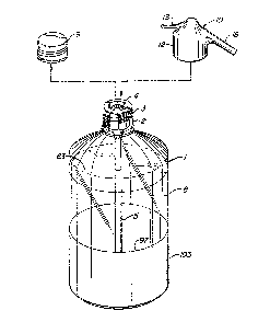
Figure 1 is a perspective view of the container of the
present invention with the valve inserted and the cap and head
1~ removed.
Figure 2 is a cross sectional view of the container of
Figure 1 shown in an enlarged scale with the midsection of the
container removed. Portions of the valve mechanism are not shown
in section for purposes of clarity in showing their relationship
with the rest of the mechanism. The pre~erred valve and plug
apparatus is shown. One of the forms of the syphon tube is
shown.
Figure 3 is a cross section of a portion of the
container on an enlarged scale with the cap removed and a head
member attached to the form of the valve shown in Figure 2.
Figure 4 is an exploded perspective view of the head,
valve and a portion of the syphon tube shown in Figures 1 - 3.
Figure 5 is an enlarged side view of the container of
the present invention with a portion in cross section. The
bottle is attached to a base for convenience in s~anding in a
vertical position. This view shows the shape of the bottle prior
to filling.
Figure 6 is a side view of the container of Yigure 5
with portions in cross section. The container is shown filled
with carbonated water and is under pressure of between 90 to 150
psi. The valve and disposable cap are shown on the sealed and
filled container.
Figure 7 is a cross-section view of another syphon head
assembly and package incorporating the assembly in accordance
with the invention.
Figure 8 is an exploded perspective view o~ the syphon
head assembly shown in Figure 7.
- 10 -
Figure 9 is a cross-section view of a portion of the
package shown in Figures 7 and 8.
Figure 10 is a cross-section view slmilar to Figure 1,
but showing the package of Figures 7-9 in use.
Figure 11 is an external perspective view of still
another syphon head and package in accordance with the
invention.
Figure 12 is a cross section view taken along the line
4-4 in Figure 11.
Figure 13 is a cross-section view of the syphon head
and package shown in Figures 11 and 12 during activation.
Figure 14 is a cross-section view of the syphon head
and package shown in Figures 11 and 12-13 after activation.
Figure 15 is a cross-section view of the syphon head
and package shown in Figures 11-14 during use.
Figure 16 is an exploded perspective and partial
section view of a further syphon head and package embodiment in
accordance with the invention.
Figure 17 is a cross section view of a completed
package incorporating the syphon head of Figure 16.
DESCRIPTION OF THE PREFER~ED EMBODIMENTS
Turning now to the drawings, more particularly to
Figure 1, the method of the present invention for storing and
dispensing fluids containered under gas pressure comprises
selecting a plastic, metal, composite or other substantially non-
frangible container 1 capable of safely withstanding in excess of
three atmospheres of pressure and preEerably a 1.8 liter bottle
capable of safely carrying liquids at 150 psi (10 atmospheres).
The container is formed with a neck portion 2 having an external
attachment member 3. Preferably, the bottle is an 18 to 20 mil
polyester terephthalate (PET) bottle. Polyester terephthalate
(PET) is furnished by various manufacturers, including Eastman
Chemical Products, Inc. One of the manufacturers of the bottle
is Plaxicon Company in the City of Industry, California usiny
equipment and molds manufactured by NISI ASB Machine Company,
Ltd. of Japan, with offices in Torrance, California. The
unusually high strength is due to the bi-axial orientation of the
- 11 -
3~i~9
molecules in the plastic. Additional information on bottle
manufacture is set forth in "A Layman's Guide to Pet Chemistry
and Processing", Edward E. Dennison, Eastman Chemical Yroducts,
Inc. and "One-Stage Processing of Pet Bottles", Eastman Kodak
Company. The external attachment member on the outside wall of
the neck may be the formation of screw threads 3 in the plastic.
A valve means 4 is selected which is mounted
substantially within the container neck portion for maintaining
gas pressure of at least three atmospheres and preferably up to
about 150 psi or about 10 atmospheres. A tube 5, commonly known
as a syphon tube, is connected to the valve and has a distal end
6 which extends to a point adjacent to the bottom 7. The fluid
flows up through the hollow syphon tube and through the valve
when opened. The container is filled with liquid 8, such as
carbonated water pressurized to about 10 atmospheres.
A cap member 9 for removably covering the opening in
the neck portion of the bottle is selected, which ~s removed
prior to placing the head on the bottle and dispensing the fluid.
The cap preferably is of light weight aluminum formed with
~0 internal threads, tamper proof and recyclable or disposable.
The cap should have a thin flexible seal member 54 (Figure 2~ ~or
preventing the inside of the bottle and valve from becoming
contaminated in the distribution system. The cap is not under
pressure, unlike all caps for lightly carbonated beverages.
The last step in the method is to select a.head member
10, which is removably affixed to the external attachment member
on the neck portion of the container. A preferred means of
attachment is by internal threads 11 formed on the inside of wall
12 of the head member. The head member has a manually engageable
valve actuating member, such as a lever 13. A remote valve
actuating member, such as a pin 14, is selectively operable by
the valve actuating member and is positioned for engagement with
the valve means. A substantially impermeable liquid and gas
sealing means, such as a rubber membrane 15, separates the
manually engageable valve actuating member 13 and the remote
valve actuating member 14. The head is formed with a chamber 16
- 12 -
~IL3~ 56~
which receives the fluid and channels it to a channel 17 in spout
18.
In F'igures 2, 3, and 4, a safety neck plug member 19 is
shown which encloses the valve means and is integrally connected
to the syphon tube 5. The neck plug member is preferably
attach~d to the inside wall 20 of the container by an adhesive.
A suitable adhesive is General Electric RTV Silicon ~dhesive.
Another method of attaching wall 49 of neck plug 19 is to use a
solvent to soften the PET and weld the plug to the neck wall of
the container. Spin welding may also be employed.
Continuing to refer to Figures 2, 3, and 4, the valve
means includes an inner chamber 21 formed in neck plug member 19
having upper and lower portions 22 and 23. A valve seat 24 is
formed in the upper portion of the valve chamber. This may
simply be an annular protrusion. A valve cup 25 is positioned
for registration with the valve seat in a valve closed position
and is movable to a valve open position away from the valve seat.
Sealing means, such as a rubber washer 26, is positioned within
the cup for sealing registration with the valve seat in the valve
closed position. A spring retainer member 27 is mounted in the
lower portion 23 of the chamber 21 and flared portion 101 of the
syphon tube and a spring member 28 is mounted in the spring
retainer member and biases the valve cup to the valve closed
position.
The manually operable means for selectively opening the
valve for release of the contents of the container may be any
member capable of depressing the valve cup 25. A suitable head
member 10 is illustrated in Figures 3 and 4 for actuating the
valve. A guide member 29 having threads 99 is threadably
inserted into an opening 30 formed in the head to engage head
internal threads 31. Pin 14 is mounted for vertical
reciprocation within opening 32 of the guide member. Lever 13 is
formed with a protrusion 33 which bears on cup 34. Injection
molded plastic washer 35 bears against annular protrusion 36
which surrounds cup 34. The lever pivots about end point 100.
Assembly and operation of the valve and head
illustrated in ~igures 2-4 is as follows. A syphon tube 5 is
- 13 -
3L3()0S&~
selected having a length which will reach to a point adjacent
the bottom of the container. Since the container is plastic and
will expand with increased pressure from increased temperature
and shrink with the loss of pressure, it is advisable to select
an end member 37 which is frictionally placed over the distal end
6 in a telescoping manner 50 that if the bottom of the bottle
pushes up against flared end 38, the end member 37 will simply
slip over the distal end 6. Note that op~nings 39 formed in the
end member 37 permit liquid to flow into the syphon tube even
though the end member is pressed tightly against the bottom wall
of the bottle. syphon tube 5 is formed with an outwardly
extending flange 40. An annular rib 41 registers with a matching
groove 42 in the plug member 19. Spring retainer 27 snap fits
into the bottom of plug 19 and is inserted into enlarged opening
43. Spring 28 is then placed in the spring retainer so that its
bottom end rests on abutment 45 and the top portion encircles
protrusion 46 on valve cup 25. Rubber washer 26 is placed in
valve cup 25, which in turn is placed on the spring 28. Note
that washer 26 may be formed with a small opening 47 to retain
the end 48 of pin 14. Safety neck plug member 19 is then adhered
to flange 40 of the syphon tube thereby compressing spring 28 and
forcing sealing washer 26 into sealing engagement with valve seat
24 formed in the plug member. The entire plug and syphon tube
assembly is then placed into the container and the side wall 49
is adhered to the inner neck wall of the container by a suitable
adhesive or by spin welding.
Filling of the container with carbonated water is as
follows. A suitable filling apparatus depresses valve cup 25 and
the liquid enters through opening 50 in plug member 19 and into
inner chamber 21. The water is forced past openings 51 and 52
and into syphon tube 5. The water f lows through end member 37
and then into the bottle. When the container is filled to the
desired amount, the valve cup is released and spring 28 forces
the cup and washer 26 into sealing engagement with valve seat 24.
Pressure in the container also tends to force washer 26 into
sealing engagement. A cap 9 is then threaded onto the container
to prevent contaminat~on of the end surface 53 and opening 50 of
- 14 -
the plug. The cap member may be provided with a flexible sealing
member 54 to further enhance the seal to prevent contamination.
As previously noted, the cap is not under any pressure since the
container pressure is entirely held by the sealing washer 26
within the safety plug.
Another important feature is the fact that the entire
valve means and plug member is within the neck of the bottle
except for a thin flange 55 which may rest on the upper rim 56 of
the bottle. Flange 55 mechanically prevents the plug from
slipping inside the bottle when the plug is first assembled and
adhered to the inside wall of the neck of the container. It may
also serve to provide an abutment when the cap is screwed onto
the bottle.
The container is shipped through the distribution chain
with the cap on and without any head mechanism. The container is
shelved in supermarkets and other retail stores, where it is
purchased directly by the ultimate consumer and carried to a home
or business place. The container is chilled in the refrigerator
and, when ready for consumption, the cap 9 is removed from the
bottle and the head member 10 is screwed onto the container. The
guide member 29 mates with conical surface 53, which is a rigid
non-compressible sealing surface, at its matching concave surface
58. Pin 14 is inserted through opening 50 in the plug member and
opening 47 in washer 26. Preferably there is a detent 59 into
which the end 48 of pin 14 is inserted. All o~ the above
operations are carried out without releasing any pressure from
the container. Note that there are no compressible parts. All
of the parts have a fixed length for accurate mass assembly of
the valve and safety plug. In order to withdraw a part or all of
the contents of the container, it is simply necessary to depress
lever 13 inserted through opening 102 in the head 10, which
causes protrusion 33 to move downwardly against cup 34, which in
turn presses downwardly on the head 60 of pin 14 through sealin~
membrane member 15. Depression of lever 13 causes pin 14 to move
downwardly and end 48 to depress valve cup 25, carrying washer 26
with it. Spring 28 is compressed against abutment 45 in the
spring retainer 27. Gas pressure within the container forces the
- 15 -
~3(~0;5~9
carbonated water up through syphon tube 5, through openings 52
and 51 in the spring retainer and into inner chamber 21. The
liquid is forced between seal 26 and the valve seat 24 up past
the flutes 61 in pin 14 and into chamber 16 in the head. Drain
opening 62 permits the liquid under pressure to be propelled
through channel 98 in guide member 29 and through channel 17 in
the spout ~8. As soon as the lever 13 is released, spring 2~
forces valve cup 25 to move upwardly and to seal washer 26
against valve seat 24. Pin 14 is forced upwardly and causes
lever 13 to return to its raised position. Thus, the container
remains charged with sufficient gas to completely empty the
container whenever desired at a later time. There is no escape
of gases while the lever is in the raised position, since the gas
remains in the upper portion of the container and continues to
act on the surface 63 of the water, rather than on the seal
between washer 26 and seat 24.
It is standard practice in industry to provide a
plastic base member for plastic bottles. The drawings
illustrate such a standard base as indicated by the number 103.
The base is attached to the bottle by applying adhesive at areas
g4 and 95. By applying the adhesive to the base of the bottle
and an upper part of the base, the base will remain affixed to
the bottle in spite of the expansion and contraction of the
bottle which results from the varying pressure in the bottle, as
affected by varying temperature and varying fill levels of the
bottle. The difference in shape of the bottle is shown in Figure
5 when the bottle is empty and in Figure 6, which shows the shape
of the bottle when it is filled and pressurized. Note
particularly the indentation along line 96 in Figure 5 at a point
just above the top edge 97 of the base 103. In Figure 6, when
the bottle is filled, indent 96 disappears and becomes a smooth
curved lineO Some vertical growth occurs in the bottle, but it
is not as dramatic as the diameter expansion. The difference in
vertical height is, however, of sufficient importance that is
necessary to make provision for this dimensional change as has
been described above in the various syphon tube end members and
the provision for openings in the edge of the end member.
- 16 -
.. ~,
~3~
It is n~t intended that cap 9 be subject to pressure at
any time. If, however the valve should leak, and build-up
pressure, danger from the cap may be obviated by providing a
plurality of vertical slots in the outer sidewall of the neck of
the bottle which cross threads 3. Thus, when the cap is
loosened, if there should accidently happen to be any pressure
against the cap, the pressure would safely vent through the
vertical slots to atmosphere, the instant the cap seal was
broken. The vertical slot system is presently found on plastic
bottles which are under light carbonation.
Figure 7 shows a syphon assembly 110 and a seltzer
water package 112 incorporating the syphon assembly 110, in
accordance with the invention. The package 112 includes a high
strength polyester terephthalate (PET) bottle 114 of the type
shown in Figures 1-3 and 5-6, having a wall thickness of from
about 1~ to 20 thousandths of an inch. The bottle 114 has a
necked opening 116 with exterior threads 118. The syphon
assembly 110 includes an insert assembly 120 (see also Figure 8),
bonded to the inside wall 122 of the necked opening 116 and
extending into the bottle 114. A head assembly 124 (see also
Figure 8) is attached to the necked opening by means of threads
126 on body 128, which mate with the threads 118 on the necked
opening 116. When assembled in this manner, the head assembly
124 engages the insert assembly 120 during use of the seltzer
water package 112.
The insert assembly 120 includes a tube 130 which
extends from the necked opening 116 into the seltzer water 132 in
bottle 114 and to bottom 134 of the bottle. Openings 136 are
provided at end 138 of the tube 130 to allow the seltzer water
132 to enter the tube 130.
The tube 130 has a flanged upper end 140 within the
necked opening 116. A resilient, substantially frustoconical
shaped valve sealing member 142 rests on end 140 of the tube 130.
Insert 144 fits over the valve sealing member 142 and is bonded
to edge 146 of the tube end 140. The tube end 140 and insert 144
are both bonded in sealing engagement to the interior surface 122
of necked opening 116. Valve sealing member 142 has a raised
- 17 -
~3~S~
portion 148, which normally seals centrally disposed passageway
150, which extends through the insert 144. A cruciform cross-
section valve guide 152 extends upward from the raised portion
148 into the passageway 150. Openlngs 154 are provided around
the raised portion 148 through the valve sealing member 142.
Figure 9 shows the necked portion 116 of the bottle 114
and the insert assembly as the packaged seltzer water 132 is
sold. A conventional aluminum twist-off cap 156 is fastened over
the necked opening 116 by means of the screw threads 118.
Pressure from the seltzer water 132 in bottle 114 is not applied
to the cap 156 because passageway 150 is sealed by the raised
portion 1~8 o~ the valve sealing member 142.
In use of the package 112, the purchaser removes the
cap 156 and replaces it with the syphon head assembly 124, as
shown in Figures 7 and 8. The package 112 is then ready to
dispense the seltzer water 132.
The head assembly 124 includes a one-piece actuator
160, consisting of an actuating rod 162, a diaphragm 164 and a
ring 166 for bonding the actuator 160 to body 128 of the head
assembly 124. Bend 168 in the resilient diaphragm 164 provides
spring tension in the diaphragm. Actuating rod 162 extends above
the diaphragm 164 and has a curved end 170, which engages curved
surface 172 of lever 174. Lever 174 extends through aperture 176
in body 128 and is pivotally connected to the body 128 at 178, on
the opposite side of the body 128 from aperture 176: Actuating
rod 162 has a cruciform cross-section portion 180 which extends
downward from the diaphragm 164 to engage the cruciform cross-
section projection 152 of the valve sealing member 142 within
passageway 150. Ring 166 of the actuator 160 has an orifice 182
extending through the ring 166, to connect cavity 18~, defined by
: the actuator 160 and the insert 144, to bore 186 within spigot
188.
Figure 10 shows the syphon assembly 110 in its open
position, to discharge seltzer water 132 through spigot 188. As
shown, when the lever 174 is depressed, actuating rod 162 is
pushed downward, exerting force on the valve sealing member 142,
deforming it away from sealing engagement with passageway 150.
- 18 -
The seltzer water flows through apertures 154, passageway 150,
cavity 184, and orifice 182 to spigot 188. When lever 174 is
released, spring force from diaphragm 164 moves actuating rod 162
and lever 174 upwards, back to the position shown in Figure 7,
allowing valve sealing member 142 to assume its normal position
sealing passageway 150.
In practice, tube 130, valve sealing member 142, insert
144, activator 160, head body 128 and lever 174 are preferably
separately fabricated from a suitable plastic material in a
molding operation. For this purpose, an injection molded co-
polyester plastic is preferably employed. The valve sealing
member 142 is placed on flanged end 140 of the tube 130, and
insert 144 is then bonded to rim 146 of the end 140, such as by
spin welding. The completed insert may then be placed into
15 bottle 114 through necked opening 116. The insert assembly 120
is then bonded at insert 144 in sealing engagement to the
interior wall 122 of the necked opening 116, such as by spin
welding or with a suitable adhesive. Similarly, the actuator 160
is bonded at ring 166 to head body 128, such as by spin welding.
Turning now to Figures 11 and 12, there is shown
another syphon head closure 210 in accordance with the
invention. The head 210 includes a body 212 with tapered flanges
214 for attachment to both inside surface 213 and outside surface
215 of neck 217 of plastic bottle 219 by spin or ultrasonic
25 welding. A spigot 216 incorporates a passageway 218 through the
body 212, communicating with interior surface 220 of the body
212. An actuating lever 222 is attached to exterior surface 224
of the body 212 by first and second break away filaments 226 and
228 and by a thicker, resilient biasing ribbon 230. A top 232 is
30 attached to the body 212 by flexible hinge 234. The top 232 is
configured to fit flange 236 of the body 212 in a snap fit. An
upwardly extending actuating rod 238 is centrally disposed within
body 212, and is attached to interior surface 220 of the body 212
by a resilient, flexible diaphragm 240. The diaphragm 240
35 divides the head 212 into an upper chamber 242 and a lower
chamber 244. Actuating rod 238 has a cavity 246 extending into
the rod 238 and dimensioned to receive end 248 of the lever 222.
- 19 -
:ilL313 C)~i6;~
In practice, all of the parts of the head closure 210
are preferable fabricated together from a suitable plastic
material in a single molding step. For this purpose, an
injection molded co-polyester plastic is preferably employed.
The body 212, lever 222, cap 232 and spigot 216 are formed by a
one piece mold cavity, with separate cores from above into upper
chamber 242, from below into lower chamber 244 and from the side
to form the rod 238, flexible diaphragm 240 and the passageway
218. A slider within the core used to form spigot 216 forms the
passageway 218.
Prior to attachment of the body 212 to a container, the
syphon tube 256 is attached to the inside surface 220 of the body
212, by spin or ultrasonic welding the flange 258 in place. Tip
257 of rod 238 engages opening 259 of tube 256 in a sealing ~it
when tube 256 is in place. After the syphon tube 256 is attached
in the body 212, the top 232 is snapped into position in flange
236, as shown in Figure 12. Figure 12 shows closure 210 in place
on neck 217 of a plastic bottle 219, permanently attached by
welding. Flange 274 extending around the neck of the bottle 217
provides support for the body 212 against lateral shearing
forces, such as might occur if the bottle 219 were dropped. The
bottle 219 is filled with highly carbonated water 276 through
spigot 216, as is conventional in seltzer bottling, by inserting
a suitable member through opening 278 in body 212 to engage rod
238 to apply force for moving end 257 of the ro~ away from
opening 259, thus opening the valve assembly and allowing the
highly carbonated water 276 to flow into the bottle 219. This
procedure is explained more fully below in connection with
Figures 18-22. ~hen so filled, the bottle 219 is stored, shipped
and sold in the form shown in Figure 12. Since lever 222 must be
inserted through opening 278 to engage the rod 238 to discharge
the highly carbonated water 276 from the bottle 219, the presence
of intact break away filaments 226 and 228 on the package assures
the user that the package 211 has not been tampered with prior to
sale. If desired, a removable label or other sealing strip may
also be placed over the opening 278 during storage and shipment
of the package 211.
- 20 -
~3~
Figure 13 shows the syphon head closure 210 during the
process of activating the syphon head closure for dispensing the
seltzer 276 from bottl~ 219 by insertion of the lever 222 through
opening 278. The user pulls upward on the lever handle 280,
first rupturing the filament 226. Spring strip 230 guides the
lever 222 with continued upward force on the handle 280, so that
end 248 of the lever 222 enters the opening 278. The second
break away filament 228 breaks during this travel. The spring
strip 230 is configured so that it will guide the end 248 into
cavity 246 in rod 23~ to give the configuration shown in Figure
14. Nipples 2~1 on either side of the lever 222 engage inside
surface 220 of the upper chamber 242 to keep the lever 222 in
place once it has been inserted through opening 2~8. Edge 283 of
opening 278 serves as a fulcrum for raising rod 238 when downward
force is applied to handle 280.
Figure 15 shows the syphon head closure 210 actuated by
a user. Downward force on the handle 280 of the lever 222 is
converted to upward force on the rod 238 by fulcrum edge 283,
thus moving tip 257 out of sealing engagement with opening 259 in
the syphon tube 256. The seltzer water 276 is then discharged by
the carbon dioxide pressure in bottle 219 through opening 259
into lower chamber 244 and out passageway 218 of spigot 216.
When the user releases the downward force on handle 280 of lever
222, the downward biasing force of diaphragm 240 on rod 238
returns the head closure 210 to the position shown in Figure 14,
with tip 257 sealing the opening 259. If desired, a compressed
spring can be inserted between end 285 of rod 238 and top 232,
and top 232 bonded in place, to provide additional downward
biasing force on rod 238. When the bottle 219 is empty, it and
the head closure 210 are recycled or discarded.
Figures 16 and 17 show a third embodiment of a package
300 in accordance with the invention. This package 300 includes
an insert assembly 302, which is inserted in the neck 350 of a
bottle 352, and a head closure 304, which is screwed by threads
306 onto mating threads on the neck of the bottle. With this
embodiment, the bottle 352 containing the seltzer water 356 is
sold with the insert assembly 302 in place in the neck of the
- 21 -
ifl9
bottle and a conventional aluminum twist of~ or plastic snap on
cap fastened over the neck of the bottle. The end user replaces
the cap with the head closure 304.
The insert assembly 302 includes a tube 310 which
extends from the neck 350 of the bottle into the seltzer water
356 and to the bottom of the bottle 352. Openings 312 are
provided at end 314 of the tube 310 to allow the seltzer water to
enter the tube 310. The tube 310 has a ~langed upper end 316
within the neck of the bottle. A resilient, substantially
frustoconical shaped valve sealing member 318 rests on end 316 of
the tube 310. Insert 320 fits over the valve sealing member 318
and is bonded to edge 322 of the tube end 316. The tube end 316
and insert 320 are both bonded in sealing engagement to interior
surface 358 of the bottle neck. Valve sealing member 318 has a
raised portion 324, which normally seals centrally disposed
passageway 326, which extends through the insert 320. A
cruciform cross section valve guide 328 extends upward from the
raised portion 324 into the passageway 326. Openings 330 are
provided around the raised portion 324 through the valve sealing
member 318.
As in the Figures 11-15 embodiment, the head 304 has a
lever 340, mounted on exterior surface 360 of head body 362. To
activate the head 304, lever 340 is extended through an opening
342 to engage a vertically disposed actuating rod 344. Cruciform
cross section end 346 of the rod 344 is configured to engage the
valve guide 328.
The head 304 is provided separately from the seltzer
~ater package 300 including the insert assembly 302 and a
conventional aluminum twist off or plastic snap on cap. After
replacing the cap with the head 304, the user separates lever 340
from body 362 of the head 304 in the same manner as in the
Figures 11-15 embodiment, to insert the lever 340 through
opening 342, aperture 348 extending transversely through rod 344
and into socket 364. When the seltzer package is empty, the user
may remove the head 304 for use with another seltzer package.
Other than as shown and described above, the construction and
- 22 -
;. .,
operation of the Figures 12-13 embodiment is the same as the
Figures 11-15 embodiment.
It should be apparent to those skilled in the art that
various changes in form and details of the invention as shown
and described may be made. It is intended that such changes be
included within the spirit and scope of the claims appended
hereto.
- 23 -