Note : Les descriptions sont présentées dans la langue officielle dans laquelle elles ont été soumises.
~L30(35~9
Background of the Invention
_
The present invention relates to a vacuum pump and
more particularly to a tu~bo-molecular vacuum pump for
rela~ively high pressure.
Molecular pumps produce a constant pressure ratio in
the reyion of the molecular flow and a constant pressure
differential in the region of the laminar flow. In molecular
pumps in the style of Gaede, Hollweck or Siegbahn, for example,
with very narrow gaps, both the pressure ratio in the molecular
region and the pressure differential in the laminar region are
particularly high. Turbo-molecular pumps, as a further develop-
ment of the molecular pumps of earlier design, with larger
gaps, produce a very high pressure ratio in the molecular region,
but only a small pressure differential in the laminar reglon.
A molecular pump of Hollweck's design is disclosed,
for example, in 5wiss Patent No. 222 288~ The fundamental
construction and the mode of operatlon of a turbo-molecular
pump are described by W. Becker in the journal "Vakuumtechnik",
No. 9/10 - 1966 under the title "The turbo-molecular pump".
Both types of pumps are molecular pumps, that is to say, they
work in the molecular flow region and the gas transport is
effected by transmitting pulses from moved walls to the molecules
of the gas to be conveyed.
13a)~S~
The working range of turbo-molecu:Lar pumps is limited,
however, in the direction of higher pressures because they are
only fully effective in the molecular flow region. The
molecular flow region is limited by the pressure at which the
mean free path of the molecules drops to the order of magnitude
of the dimensions of the vessel.
Tuxbo-molecular pumps, therefore, work only in combin-
ation with backing or fore pumps. As a rule, these are two-
stage sliding-vane rotary pumps. If it were possible to shift
the working range of turbo-molecular pumps in the direction of
higher pressures, the expense for producing the backing or fore
pressure could then be reduced. For example, single-stage
sliding vane rotary pumps would be sufficient. In other cases,
oil-sealed sliding-vane rotary pumps could be replaced by dry
diaphragm pumps, for example.
The working range of a turbo~molecular pump can be
shifted in the direction of higher pressures by fitting a
molecular pump of the Hollweck pump type following on the fore
vacuum stage. Such combinations are described, for example,
in D~-AS 2 409 ~57 and in EP 01 2g 709.
It is essential for the operation of such a Hollweck
pump that the spacing between the rotor and stator should be
very small. Only then does it work, even at relatively high
pressures, as a turbo-molecular pump still in the molecular flow
~3(;~S7~
range and develop its full pressure ratio which shifts ~he
- working range ln the direction of higher pressures~ Theory
and experimental results call for spacing between the rotor
and stator of a few hundredths of millimeters.
Another prerequisite for satisfactory efficiency of
a molecular pump is a high speed of rotation of the rotor.
-These two extreme requirements, high speed of rotation
and narrow gaps, involve two conditions for the design of a
molecular pump which are difficult to reconcile with one another.
The higher the speed of rotation, the greater must be the
minimum spacing between rotating and stationary parts, in order
to prevent a collision. With very high speeds of rotation and
very narrow gaps, all designs of molecular pumps hitherto known,
apart from turbo-molecular pumps, represent extremely critical
structural units. This applies in particular when the gap is
: further reduced by the thermal expansion o~ the rotor caused by
the electric drive, friction losses and compression work. Then
the rotor may easily.run against the stator as a consequence of
which, destruction of the pump may easily occur in many cases.
: SUMMARY OF THE INVENTION
:
The present invention seeks to provide a molecular pump
consisting of a turbo-molecular pump and a fore vacuum stage
in the form of a molecular pump which is constructed in the
~3s)~579
in the manner o~ a Hollweck pump. The molecular pump serving
as a backing or fore s~age should be designed so that reliable
operation is guaranteed under the extreme conditions of very
narrow gaps between rotor and stator and high speeds of
rotation, even in the event of expansion of the rotor, for
example, through a rise in temperature.
According to a first aspect of the present invention,
there is provided a molecular pump comprising a rotor having
a stator associated therewith and a bearing axially locating
said rotor, wherein the rotor eomprises a eomplete eone having
an apex or a truneated eone defining an imaginary apex, said
cone or truncated cone having helical grooves thereon, and
said stator comprising a conical configuration adapted to the
conical shape of the rotor, with the bearing being located at
the apex, whether real or imaginary.
According to a second aspect of the present invention,
there is provided a turbo-molecular vacuum pump having a high
vacuum side and a fore vaeuum side and eomprising a rotor
having a stator associated therewith and a bearing axially
loeating said rotor, said rotor and said stator comprising
respective discs, witha part of said rotor adjacent to the
fore vacuum side being formed by a cone having an apex or a
truncated cone defining an imaginary apex, said cone or
truncated cone having helical grooves thereon and said stator
comprising a eonieal configuration adapted to the conical shape
s~
of said rotor, said bearing being at said apex of said cone
or at said imaginary apex of said truncated cone.
The various features of novelty which characterize
the inven~ion are pointed out with particularity in the claims
annexed to and forming a part of this disclosure. For a better
understanding of the invention, its operating advantages and the
specific objectives attained by its use, reference should be had
to the drawings and descri?tive matter in which there ara
illustrated and described the preferred embodiments of the
invention.
BRIEF DESCRIPTION OF THE DRAWINGS
In the drawings:
.
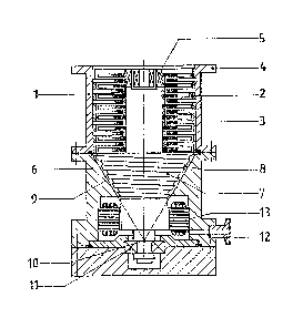
Fig. 1 is a sectional view showing a turbo-molecular
pump according to a first embodiment of the present invention,
wherein the apex of the cone is remote from the turbo-molecular
pump stage;
Fig. 2 is a sectional view showing a turbo-molecular
pump according to a second embodiment of the present invention,
wherein the apex of the cone is adjacent to the turbo-molecular
.. .
pump stage; and
~ 3~(~579
Fig. 3 is a schematic diagraph showing a detail
of Fig. 1.
DETAILED DESCRIPTION OF THE: PREFERRED EMBODIMENTS
Referring now to the drawings and particularly Figs.
1 and 2, two different forms of the invention are illustrated
which differ from one another fundamentally in that in Fig. 1,
the apex of the cone of the rotor of the molecular pump is
adjacent to the backing-pressure side and in Fig. 2, it is
adjacent the side where the turbo-molecular pump stage is
situated. Thus, in the embodiment of Fig. 2, centrifugal force
effects can be utilized additionally as a pumping aidO
In the housing 1 of the turbo-molecular pump stage,
there are rotor discs 2 and stator discs 3. The part at the
high-vacuum side is terminated by a flange 4. A bearing 5,
which may be constructed in the form of a magnetic bearing,
for example, serves to guide the rotor radially. This bearing
5 does not necessarily have to be fitted at the high vacuum
side. If an oil-lubricated ball bearing is used, it is prefer-
able to dispose this at the ~acuum side of the turbo-molecular
pump stage.
The part of the-pump combination at the vacuum side
is designated as 6. The rotor of this pump stage is formed by
a truncated cone 7 with helical grooves 80 The associated
--7--
'13(~7~
stator consists of a cone 9 adapted to the conical ~ape of
the rotor. The imaginary apex of the truncated cone 7 is
at lO. At this point, a bearing ll is also fitted which
locates the rotor axially. The backing or fore vacuum
connection is designated 12 and the electric drive moto- 13.
The geomet~ical relationships ~n the event of heat
expansion of the rotor are illustrated in Fig. 3. If the
rotor is axially loeated in the apex o ti~e cone or in the
imaginary apex o the truncated cone lO, the gap width a
between the rotor and stator remains eonstant in the event of
an isotropic expansion of the rotor~
Thus, from the foregoing, it will be seen that the
present invention provides a turbo-molecular vacuum pump
comprisiny a rotor and an associated stator and having a high
vacuum side with rotor discs and stator discs, the ~art o the
rotor adjacent the ore vacuum side being formed by a cone or
a truncated cone on which there are helical grooves and the
stator consisting of a eonical eonfiguration adapted to the
conical shape of -the rotor, with the bearing which locates
the rotor axially bsing at the apex of the cone or at the
imaginary apex of the truncated cone.
As a result of the fact that the bearing of this pump
eombination which loeates the rotor axially is at the apex of
the eone or in -khe imaginary apex of a truncated eone, the
~3~5~
spacing between the rotor and stator of the pump stage thus
formed remains constant in the event of expansion of the
rotor. The changes in the spacing between rotor discs and
stator discs of the turbo-molecular pump stage vary, as in
the known designs of turbo-molecular pumps, within the tolerance
limits which are greater by about the fact 10 than in a
molecular pump constructed in the manner of a ~ollweck pump.
The fact tha-t the width of the gap at the conical
molecular pump remains constant in the event of expansion of
the rotor, if the cone is located at the tip, can be shown
with refererence to Fig. 3. In the event of isotropic heat
expansion of the rotor:
A lr = lr
~ la la
Thus, the angle ~ remains constant and a point P on the rotor
is displaced paralleI to the envelope of the cone to P'.
In the example of Fig. 2, the tip of the cone is at
the side of the rotor adjacent the turbo-molecular pump stage.
~ith this design, the same conditions apply for gap ~idth _.
In this case, however, there is also the ad~antage that
centrifugal force causes an additional pumping effect. On
emerging from the trubo-molecular pump, the gas is drawn into
the backing or fore stage with a small radius and expelled with
a large radius.
_g_
~L3(~ S79i
The conical molecular pump stage c~an, of course, also
be used advantageously either separately or in conjunction with
a different type of high vacuum pump.
The present invention also provides a molecular pump
comprising a rotor and an associated stator, wherein the rotor
is formed by a cone or a truncated cone on which there are
helical grooves and the stator consists of a cone adapted to
the conical shape of the rotor, the hearing which locates the
rotor axially being at the pointed end oE the cone or at the
imaginary tip o~ the truncated cone.
While specific embodiments of the invention have been
shown and described in detail to illustrate the application of
the inventive principles, it will be understaod that the
invention may be embadied otherwise without departing rom such
principles.
--10--