Note : Les descriptions sont présentées dans la langue officielle dans laquelle elles ont été soumises.
13~;)0948
METHOD AND APPARATUS` FOR ORIENTING AND LOADING
RIM-FIRE CARTRIDGES
Field of the Invention
The present invention relates to a method and an
05 apparatus for loading cartridges into 2 magazine and,
in particular, to a method and apparatus for orienting
a plurality of unoriented rim-fire cartridges and load-
ing the oriented cartridges into a magazine.
Background Information
A number of types of firearms can be used in con-
junction with magazines for holding cartridges to as-
sist in feeding the cartridges into the firearm. When
the magazines are designed to be reusable, the depleted
magazines must be reloaded with cartridges. Many
reusable magazines can be reloaded by hand without the
use of any apparatus. However, hand reloading is often -
slow and tedious so that it is useful to provide an ap-
paratus for assisting in the reloading process. A num-
ber of characteristics of cartridges and magazines
present problems which a useful reloading apparatus
must solve. --
Cartridges are produced in a variety of configura-
tions ~ncluding center-fire cartridges which are typi-
.
cally in the shape of a cylinder with a rounded orpointed end and rim-fire cartridges, i.e. cartridges
which have a generally cylindrical body portion but
also have a rim of a larger diameter than the body
diameter. Rim-fire cartridges are somewhat more dif-
ficult to store, handle, and load because thecartridges do not stack in a regular or linear fashion
as center-fire cartridges do. Thus, devices for as-
sisting in loading cartridges into magazines preferably
should be able to accommodate a variety of cartridge
shapes and, particularly, should be capable of accom-
modating rim-fire cartridges.
~y~
_.__ _. . . .. . . . . . . .
. . .
~ . .. . .. . .. , .: .
~300948 ~`
Cartridges are often sold packaged in an
unoriented manner, i.e. in which the longitudinal axes
of the cartridges are not substantially parallel or
coplanar with each other. Because a cartridge magazine
requires that the cartridges be positioned in an
oriented fashion, a useful apparatus for loading should
both provide for orienting the cartridges and then
placing the oriented cartridges into the magazina.
Certain magazines re~uire that cartridges be posi-
tioned into the magazine in a pa~ticular manner.
Specifically, magazines for use with rim-fire
cartridges often require that the cartridges be (1~ in-
serted into the magazine one-at-a-time, i.e. such that
the cartridge which is being inserted into the magazine
moves in a direction or at an angle different from the
direction or angle of subsequent cartridges which are
to be placed into the magazine and/or (2) that the
cartridges be positioned into the magazine by first
placing the cartridge at a first angle with respect to
the magazine opening and then moving or pushing the
cartridge while changing the angle to a second angle
with respect to the magazine opening. A useful loading
apparatus thus should be capable of a configuration
which will result in a one-at-a-time and/or multiple
angle insertion of cartridge.
The oriented cartridges supplied to the loader ap-
paratus should be in a column of sufficient number that
the loading into magazines can be performed efficiently
without unnecessary interruptions. However, a device
for holding a single column of a large number of
cartridges results in an awkward and unwieldy ap-
paratus. Thus, it is useful to provide a cartridge
orienting and loading method and apparatus which sup-
1300948
plies a column of cartridges in a large number butwithout being of cumbersome dimensions.
Because a loading mechanism may be used in field
05 or outdoor conditions, devices which depend upon
springs or motors are subject to freezing from exposure
to cold and/or corrosion or deterioration from exposure
to water and the like. Thus, it is advantageous to
provide a device which orients cartridges and can be
used for loading cartridges but which does not require
a motor or springs to orient or move the cartridges.
Summary of the Invention
The present invention relates to a method and ap-
paratus for orienting a plurality of unoriented
cartridges and loading the oriented cartridges into amagazine. The apparatus can be provided in an integral
configuration, but is preferably formed of two detach-
able portions, an orienting portion and a loading por-
tion. The orienting portion is designed to use gravity
to orient a plurality of unoriented rim-fire cartridges
using a number of rails. The rails are spaced apart
farther than the body diameter of the cartridges but
less than the rim diameter. In this manner, when
cartridges are placed adjacent to the rails, the nose-
portion of the cartridges, being heavier than the rim-
end, will tilt or move downward between the rails. The
cartridges will thus be hung from the rails by portions
of their rims with the heavy nose-portion of the
cartridges pointing down. In this configuration, the
cartridges will be substantially parallel with each
other, i.e. with the longitudinal axes of the
cartridges all substantially parallel with each other.
This orienting of the cartridges may require that the
orienting device be shaken. The device preferably con-
tains more than two rails, preferably in substantially
, ... _ . _ .. ____ __. , _ _, . .. . . .. . ..
i~O0~48
~4--
parallel configuration so that the bullets are oriented
into a number of columns.
After the cartridges are oriented, the orienting
portion is up-ended or moved to a second position so
that the oriented cartridges move in a direction per-
pendicular to their longitudinal axes to form one or
more columns of adjacent cartridges. The force of
gravity is then used to move the cartridges down a
chute towards an opening in the orienting portion.
When two or more columns of cartridges are provided, a
gate is used to direct each column, in turn, towards
the chute. The opening at the bottom of the chute is
controlled using a latch mechanism to prevent the
cartridges from leaving the orienting portion prema-
turely.
The orienting portion is then connected to theloading portion which contains an area for receiving
the orienting portion. A latch-activating cam on the
loading portion opens the latch so that a first
cartridge falls, under the force of gravity, into a
cartridge receiving device on the loading portion. An
empty or partly empty magazine is inserted in a
magazine receiving area of the loading portion. The
magazine receiving area is configured to hold the open-
ing of the magazine in a predetermined position withrespect to the cartridge receiving device.
The cartridge receiving device is movable and is
attached to a mechanism such as a cam mechanism which
controls the movement of the cartridge receiving
device. The camming mechanism for moving the cartridge
receiving device is configured to move the cartridge
through the opening of the magazine and into the
magazine in a manner which is consistent with the load-
ing re~uirements of the particular magazine. For rim-
fire cartridges, the cartridge is initially guided by
- . .
i~O0948
movement of the cartridge rim through a rim receiving
slot. The cartridge is placed in a first angular
relationship with respect to the magazine opening and
the rim portion is inserted through the opening. The
cartridge is then moved to change the angular relation-
ship to a second angle with respect to the magazine
opening as the remainder of the cartridge is inserted
through the magazine opening and into the magazine.
The camming mechanism is then returned to its original
position to permit the next cartridge to enter the
cartridge receiving device. In this manner, the
cartridges are loaded into the magazine one at a time.
As can be appreciate~, the present invention
provides a number of advantages. The invention is able
to accommodate rim-fire cartridges to assist in orient-
ing and loading such cartridges. The invention permits
orienting cartridges which are packaged in an
unoriented fashion. The invention is compatible with
the requirements of a number of magazine loading tech-
niques including one-at-a-time loading and loading by
changing the angle of the cartridge as it is inserted.
By providing for a loader which is detachable from the
orienter, the loader can be fixed for one-handed opera-
tion while the orienter can be placed in a first posi-
tion for orienting and up-ended for engagement with the
loader. A loaded magazine can be removed and an empty
magazine can be attached to the loader without separat-
ing the loader from its support. The orienting and
movement of the cartridges through the chute is en-
tirely gravity-powered and does not require use of a
motor or springs. By providing a gate for controlling
movement of cartridges, the benefits of providing a
larger number of cartridges in columnar form are
provided without the cumbersome dimensions required by
a single column device.
_ . _ _ _ . _ . . .. _ . . . .. . .
1300948
Brief Description of the Drawings
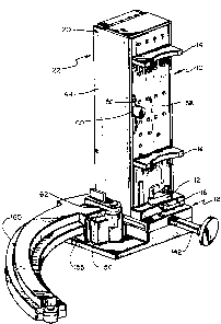
Fig. 1 is a perspective view of the loader portion
engaged with the orienter portion and with a magazine
positioned in the magazine receiving area;
Fig. 2 is a perspective view of the orienter por-
tion with the door in an opened position and with a
portion of one side wall cut away and with the gate
opening aligned with the second space;
Fig. 3 is a cross-sectional view taken along line
3-3 of Fig. 2 but with the gate opening aligned with
the third space;
Fig. 4 is a side elevational view of the orienter
portion with a part of the side wall broken away;
Fig. 5 is a bottom plan view of the orienter por-
tion showing portions of the latch in phantom lines
with the gate opening aligned with the fourth space;
Fig. 6 is a top plan view of the loader base por-
tion showing the cam and cam followers in phantom
lines; `
Fig. 7 is a front elevational view of the loader
base portion showing parts of the cartridge receiver in
phantom lines; and
FigO 8 is a perspective view of the loader base
portion.
Detailed Description of the Preferred Embodiment
The present invention relates to a method and an
apparatus for orienting a plurality of unoriented
cartridges and loading the cartridges into a magazine.
Although the orienter and loader can be provided as an
integral device, in the preferred embodiment, as best
seen in Fig. 1, the orienter 10 is detachably engaged
with the loader 12.
Referring now to Fig. 2, the orienter 10 is
.
... . . . . .
1300948 ~`
depicted in the form of a box or rectangular paral-
lelepiped. Projecting outward of one wall of the
orienter 10 are two feet 14. Posts 16 project outward
of two opposite faces of the orienter for holding the
orienter 10 adjacent the loader 12 as described below.
A door 18 is provided on one face of the orienter 10
attached by hinges 20 to provide access to the interior
of the orienter 10. The upper portion 22 of the orien-
ter 10 contains a plurality of rails with upper por-
tions 24A, 26A, 28A, 30A, 32A which are parallel to a
wall of the orienter 10 and lower portions 24B, 26B,
28B, 30B, 32B which are angled with respect to the up-
per portion. The rails are substantially parallel and
spaced apart. The distance which the rails are spaced
apart relates to the dimensions of the cartridges with
which the orienter 10 is intended to be used. The
spacing between the rails is greater than the diameter
of the cartridge body portion but less than the
diameter of the cartridge rim. In this way, the rails
define a number of slot-shaped spaces 34, 36, 38, 40.
A gate 42 is slidably mounted adjacent to a first
wall 44 of the orienter 10. The gate 42 includes an
upper portion 46 and a lower portion 48 attached so as
S to slide together using an extension 50 integrally
formed with an edge of the lower portion 48 and an arm
52 extending from the upper portion 46 to the lower
portion 48. As seen in Fig. 4, a rod 54 extends out-
ward from the gate 42 through a slot 56 formed in a
second side wall 58. A handle 60 is attached to the
rod 54 for controlling movement of the gate 42. An arm
62 extends upward from the gate 42 and resiliently
presses against a control surface 64. The arm 62 and
control surface 64 interact to releasably hold the gate
42 in one of a number of preferred positions. As
depicted in Fig. 3, the interaction of the arm 62 and
~ _ __ _ . _ . .. . .. . . ...
i300948
control surface 64 is accomplished by providing the
control surface 64 with a number of depressions or
notches 66A, 66B, 66C, 66D and providing a protrusion
05 such as an integrally molded detent 68 attached to the
arm 62. When the gate 42 is positioned such that the
protrusion 68 aligns with one of the notches 66, the
gate 42 is releasably held in such position.
The upper portion 46 is spaced from the lower por-
tion 48 to define a space 70 between the upper portion
46 and the lower portion 48. The size of the gatespace 70 corresponds to the distance between the rails
24, 26, 28, 30, 32. The notches 66 are positioned such
that when the detent 68 is aligned with one of the
notches 66A-D, the space 70 is aligned with the lower-
~- most portion of the slots 34, 36, 38, 40 respectively.
Spacers 72, 74, 76 are resiliently mounted opposite to
and spaced from the lower portion of the first wall 44.
The lower edge 78 of the lower portion of the gate 42
is angled so that as the gate 42 is moved downward, the
lower edge 78 of the gate 42 forces the spacers 72, 74,
76, in turn, in a direction away from the first wall
44. The spacers 72, 74, 76 are dimensioned so that
when the gate space 70 is aligned with any of the slots
34, 36, 38, except the lowermost slot 40, a surface of
one or more of the spacers 72, 74, 76 will be aligned
with the surface of the lower portion 48. In this way,
the spacers 72, 74, 76 cooperate with the gate 48 and
the first wall 44 to define a chute 80 having a vari-
able dimension, depending upon the position of the gate42. The chute 80 is provided with rim guides in the
form of slots. One slot 82 is formed in the first wall
44. Another slot 84 is formed in the lower gate 48 and
is positioned to align with slots 86, 88, 90 formed in
the spacers 72, 74, 76 respectively.
The dimensions of the slots 34, 36, 38, 40, gate
, .. , , . _ _ _ .. _ _ . .. .. . . . . . . . .
.
..... ~ .. , ...... ~ . : . . . . . .
i300948
space 70, notches 66, chute 80 and gate 42 are coor-
dinated to provide for control of movement of
cartridges from the slots 34, 36, 38, 40 into the chute
05 80. Specifically, when the detent 68 is aligned with a
slot 66, the gate space 70 provides communication be-
tween one of the slots 34, 36, 38, 40 and the chute 80.
At the same time, the upper portion of the gate 46 and
the lower gate portion 48 prevent communication between
the chute 80 and any of the slots 34, 36, 38, 40 other
than that slot which is in communication with the chute
80.
An opening 92 is provided in the lower portion of
the chute 80 to allow removal of cartridges from the
orienter 10. As best seen in Fig. 5, latch 94 is
provided on the bottom surface 96 of the orienter 10.
Extending from the latch 94 is a tongue 98 extending at
least partially across the opening 92 to close the
opening 92 so as to prevent removal of cartridges
through the opening 92 until the tongue 98 is moved.
The latch 94 is slidably mounted against the bottom
surface 96 and provided with a spring 100 for urging
the tongue 98 towards the first wall 44 so as to cover
the opening 92. The spring 100 can be any type of
spring but is preferably an integrally moulded leaf
spring. The latch 94 is provided with an opening 102,
an edge 104 of which interacts with a cam on the loader
12 to move the latch 94 in a manner described below.
Referring now to Fig. 8, the loader 12 is provided
with a orienter receiving area 106 and a magazine
receiving area 108. The orienter receiving area 106
has a configuration substantially corresponding to the
size and shape of the bottom surface 96 of the orienter
10. Slots 110 are provided for receiving the posts 16.
Latches 112 are rotatably mounted adjacent to the slots
110 to hold the posts 16 in the slots 110 in the manner
1:~00948
--10--
depicted in Fig. 1. A cam 114 is positioned in the
orienter receiving area 106 and provided with a slant-
ing camming surface 116. The cam 114 is positioned05 such that when the orienter 10 is placed into the
orienter receiving area 106 and the posts 16 are
registered in the slots 110, the upper surface 116 of
the cam 114 engages with the edge 104 of the opening
102 in the latch 94 to move the latch 94 against the
urging of the spring 100. This movement of the latch
94 results in the tongue 98 being withdrawn from the
opening 92. When the orienter 10 is in the orienter
receiving area 106 in the position described, the open-
ing 92 of the chute 80 will lie directly above the
cartridge receiving area 118.
With reference also to Figs. 6 and 7, thecartridge receiving area 118 is defined by a lower sur-
face 120, first and second cartridge contact surfaces
122, 126 of a first cam follower 124 and a first
cartridge contact surface 128 of a second cam follower
130.
The first cam follower 124 and the second cam fol-
lower 130 are mounted underneath the orienter receiving
area 106. The first cam follower 124 is provided with
first and second protrusions 132, 133 extending
downward through first and second slots 134, 135. The
movement of the first cam follower 124 is thus in part
guided by the protrusions 134, 135 bearing against
edges of the slots 134, 135. The moving cam 136 is
also provided with a protrusion 138 constrained to move
within a slot 140. The moving cam 136 is attached to a
rod or plunger 142 for moving the moving cam 136.
The second cam follower 130 has an angled surface
144 adjacent to a surface 146 of the first cam follower
124. The surface 146 of the first cam follower 124 it-
self acts as a cam for the second cam follower 130.
.
.. . , -, . . .
1~00948
A spring 141 is provided to urge the moving cam
136 towards the position depicted in Fig. 6 in which
both cam followers 124, 130 are positioned farthest
05 from the magazine receiving area 108.
The magazine receiving area 108 is defined by a
back wall 150, side walls 152, 154, and a bottom sur-
face 155. The side walls 152, 154 contain grooves 156,
158 for receiving protrusions (not shown) on a magazine
160 to hold the magazine 160 properly registered in the
magazine receiving area 108. A latch 162 is rotatably
mounted adjacent to the magazine receiving area 108 and
positioned such that the latch 162 can be rotated to
hold the magazine 160 in the magazine receiving area
108 in the desired position. A groove 164 is formed in
the bottom surface 120 of the cartridge receiving area
118 leading from the cartridge receiving area 118 to
the magazine receiving area 108. A slot 166 is formed
in the orienter receiving area 106 leading to the
cartridge receiving area 118. The groove 164 and slot
166 cooperate to accommodate the rim of a cartridge and
to guide movement of the cartridge during the loading.
Operation of the preferred embodiment of this in-
vention will now be described. The orienter 10 is
detached from the loader 12 and placed in a horizontal
position, i.e. supported by the feet 14 with the door
18 facing upwards. The door 18 is opened and a
plurality of unoriented rim-fire cartridges are placed
within the orienter 10 ad;acent to the rails 24, 26,
28, 30, 32. The orienter 10 is agitated by shaking or
vibrating while maintaining the orienter 10 in a sub-
stantially, though not necessarily strictly, horizontal
position. Because the nose-portions of rim-fire
cartridges are substantially heavier than the rim-
portion of rim-fire cartridges, as the orienter 10 is
agitated, the nose-portions of the cartridges will fall
130~)948
-12-
or swing downward between the rails 24, 26, 28, 30, 32.
Since the spaces 34, 36, 38, 40 are larger than the
body diameters but less than the rim diameters, the
cartridges will be hung by their rim-portions from the
rails with the nose-portions pointing downward. By
this means, the unoriented cartridges are placed in an
oriented position, i.e. with the longitudinal axes of
the cartridges being substantially parallel and the
nose-portion of the cartridges pointing downward.
The door 18 of the orienter 10 is then closed and r~
the orienter 10 is up-ended to a position in which the
bottom surface 96 of the orienter 10 is facing downward
and the first and second side walls 44, 58 are in a
substantially vertical position. In this orientation,
the rails 24, 26, 28, 30, 32 will be in a substantially
vertical position. The force of gravity will cause the
cartridges to slide throu~h the spaces 34, 36, 38, 40
in a direction substantially perpendicular to the lon-
gitudinal axes of the cartridges so that the cartridges
will lie adjacent to each other in the lower portions
of the spaces 34, 36, 38, 40. The cartridges will thus
be positioned in a plurality of stacks or columns lying
in the spaces 34, 36, 38, 40. By a stack or column of
cartridges is meant that the longitudinal axis of any
particular cartridge in a column or stack is substan-
tially, but not necessarily precisely, parallel to the
longitudinal axis of a neighboring cartridge in the `
same column or stack. Because the rim diameters are
larger than the body diameters, the cartridges in a
column will not be as nearly parallel as was the case
when the orienter lO was in a horizontal position. Be-
cause the upper and lowsr portions of the rails 24, 26,
28, 30, 32 meet at an angle, the longitudinal axes of
cartridges in a particular column will not be coplanar.
The handle 60 of the gate 42 is moved to slide the
~3~
-13-
gate to a position in which the detent 68 is aligned
with one of the notches 66A, 66B, 66C, 66D. For pur-
poses of example, the operation of the invention will
05 be described with reference to a configuration when the
detent 68 is aligned with the third notch 66C, as
depicted in Fig. 3, In this configuration, the gate
space 70 is aligned with the lowermost portion of the
third space 38. Under the influence of gravity, the
column of cartridges in space 38 will move through the
gate space 70 and into the chute 80. Movement of the
cartridges through the chute 80 will be partially con-
trolled by the cartridge rims moving through the
grooves 82, 84, 90. The lowermost of the cartridges in
the chute 80 will abut against the tongue 98 of the
latch 94 to prevent any cartridges exiting from the
orienter 10.
The orienter 10 is engaged with the loader 12 by
positioning into the orienter receiving area 106 with
the posts 16 residing in the slots 110 and latched
therein by latches 112, as depicted in Fig. 1. In this
position, the upper surface 116 of the fixed cam 114
will move the latch 94 against the urging of the spring
100 to withdraw the tongue 98 from the chute opening
92. The lowermost cartridge in the chute 80 will then
fall by the force of gravity into the cartridge receiv-
ing area 118. An empty or partially empty magazine 160
is placed into the magazine receiving area 108 by slid-
ing protrusions on the magazine 160 through the grooves
156, 158, positioning one surface of the magazine 160
against the bottom surface 155 of the magazine receiv-
ing area 108 and rotating latch 162 to hold the
magazine 160 in the magazine receiving area 108. In
this position, the opening (not shown) of the magazine
160 is positioned ad;acent to the cartridge receiving
area 118.
. . . ~
~300948
-14-
Plunger 142 is pushed towards the orienter receiv-
ing area causing the moving cam 136 to move in a linear
fashion. As the moving cam 136 bears against the first
05 follower surface 123 of the first cam follower 124, the
first cam follower 124 moves, guided by movement of the
first and second protrusions 133, 135 through the first
leg 134A of the slot 134 and through slot 135, respec-
tively. Movement of the camming surface 146 of the
first cam follower causes movement of the second cam
follower 130 substantially parallel to the movement of
the first cam follower 124. Because the first
cartridge contact surface 122 of the first cam follower
124 and the first cartridge contact surface 128 of the
second cam follower 130 bear against the cartridge
during this pivoting movement, the cartridge is pivoted
to move the cartridge rim through the slot 166 and the
groove 164. Continued movement of the plunger 142
causes continued movement of the first and second cam
followers 124, 130 and consequent movement of the
cartridge lying in the movable cartridge receiving area
118 until the movable cam 136 reaches the cut-out por-
tion 125 of the first cam follower 124 and the first
protrusion 132 simultaneously reaches the second leg
134B of the slot 134. At this position, the cartridge
receiving area 118 has rotated to an extent that the
rim portion of the cartridge lying therein has moved
partially through the opening of the magazine 160 and
lies in a first angular relationship with respeGt to
the opening of the magazine 160.
As the plunger 142 is further pushed, the protru-
sion 132 of the first cam follower 124 moves through
the second leg 134B of the slot 134 and the second
protrusion 133 of the first cam follower 124 moves
through the second slot 135. Because the second slot
135 is angled with respect to the orientation of the
_ . _, . . .
- ~ . . .
i~O0948
--15--
second leg 134B of the first slot 134, the cartridge
receiving area will continue to move towards the open-
ing of the magazine 160 while the angular relationship
of the cartridge with respect to the opening is
changed. The second cartridge contact surface 126
bears against the nose-portion of the cartridge to push
the cartridge completely through the opening of the
magazine 160 while the angular relationship is being
changed.
The plunger 142 is now released and a spring 142
causes the plunger 142, first cam follower 124, and
second cam follower 130 to return to the original posi-
tion depicted in Fig. 6. In this configuration, the
lowermost cartridge in the orienter 10 is free to fall,
under the force of gravity, into the cartridge receiv-
ing area 118. A second activation of the plunger 142
will position the second cartridge into the magazine
160 in the same manner as described with regard to the
first cartridge. Continued use of the plunger 142 will
result in loading cartridges into the magazine 160 un-
til either the magazine 160 is full or there are no
more cartridges in the chute 80. When the chute 80 is
depleted of cartridges, the handle 60 is manipulated to
move the gate 42 so as to align the gate space 70 with
another of the spaces 34, 36, 40 so as to allow another
plurality of cartridges into the chute 80 for loading
into the magazine 160.
As an example, the gate 42 can be moved from the
position depicted in Fig. 3 to align the detent 68 with
the second notch 66B as depicted in Fig. 2. As a
result of this movement, the second spacer 74 relaxes
to a position substantially aligned with the third
spacer 76 to provide, in cooperation with the third
spacer 76 and the lower gate portion 48, a substan-
tially continuous wall for the chute 80 and a substan-
_~ _. ... .. ... . .
. .
~s
~300~8
tially continuous serias of slots 84, 88, 90 forguidance of the rims, as depicted in Fig. 2. When the
gate 42 is in this position, the upper portion 46 of
05 the gate 42 prevents communication between the first
slot 34 and the chute 80 while the lower gate portion
48 prevents communication of the third and fourth slots
38, 4Q with the chute 80.
When all cartridges in the orienter 10 have been
loaded into magazines, the orienter 10 is removed and
either replaced with a new orienter containing oriented
cartridges or is itself reused to orient a second
plurality of cartridges.
When the magazine 160 has been fully loaded, it is
removed by rotating the latch 162 and sliding the
magazine protrusions (not shown) through the slots 166.
The full magazine can then be replaced by an empty or
partially empty magazine for further loading.
As will be apparent to those skilled in the art,
although not depicted in the figures, a number of
variations on the preferred embodiment can be used.
The number of slots and rails can be varied. Com-
munication from the columns to the chute can be con-
trolled in a number of ways including a plurality of
individually opened gates, or a gate placed in another
position such as the reyion in which the upper rail
portions 24-32A meet the lower rail portions 24-32B.
Spacers 72, 74, 76 can be positioned in additional or
alternative positions, such as the region in which the
upper rail portions 24-32A meet the lower rail portions
24-32B, to assist in guiding cartridge movement.
A number of features which are described as being
manually activated can be automatically activated and a
number of automatic features can be manually activated.
For example, the automatic cam-action opening of the
latch and tongue can be accomplished manually. The
~ ~ _ . . . . . . .. .
-. .~ . . . .
i300948
-17-
spring-return of the plunger to its original position
can be accomplished manually. The manual selection of
gate positions can be accomplished automatically by
05 electronics, levers or other well-known means.
A number of features described as being internally
mounted can also be externally mounted, such as the
detent 66 and notch 68 gate controller, or the spacers
72, 74, 76.
Movement of cartridges through the opening 92 can
be controlled by devices other than the latch 94, such
as providing a gate 42 which can prevent all entry of
cartridges into the chute 80 until desired.
The particular camming mechanism 124, 130
described can be modified to provide a different move-
ment of the cartridge into the magazine 160, such as by
providing a different shape or number of cams, cam fol-
lowers, posts or slots. The movement of the cartridges
through the magazine opening, rather than being con-
trolled by cams and slots, can be controlled by a num-
ber of other devices known in the art such as gear
trains, stepping motors, electronic switches, and the
like.
Although the preferred embodiment was described in
relation to orienting and loading rim-fire cartridges,
many aspects of the invention such as the described
loading process and gating of columns to a chute can be
usefully employed in connection with orienting and
loading center-fire or rimless cartridges.
Lastly, it should be understood that the orienter
of the present invention need not be used with the par-
ticular loader described herein, but could be adapted
for use with other mechanisms. Similarly, the loader
need not be used with the particular orienter described
herein.
_ , _._ _ _ . . . . . .
-,, ~ .. . . .. . .
~300948
-18-
Although the present invention has been described
with reference to certain embodiments, it should be ap-
preciated that further modifications can be effected
05 within the spirit and scope of the invention.
`-
__, _ ... .. ,._ ,_ ~" --
. , . ~ ~ .