Sélection de la langue

Search

Sommaire du brevet 1301331 

Énoncé de désistement de responsabilité concernant l'information provenant de tiers

Une partie des informations de ce site Web a été fournie par des sources externes. Le gouvernement du Canada n'assume aucune responsabilité concernant la précision, l'actualité ou la fiabilité des informations fournies par les sources externes. Les utilisateurs qui désirent employer cette information devraient consulter directement la source des informations. Le contenu fourni par les sources externes n'est pas assujetti aux exigences sur les langues officielles, la protection des renseignements personnels et l'accessibilité.

Disponibilité de l'Abrégé et des Revendications

L'apparition de différences dans le texte et l'image des Revendications et de l'Abrégé dépend du moment auquel le document est publié. Les textes des Revendications et de l'Abrégé sont affichés :

  • lorsque la demande peut être examinée par le public;
  • lorsque le brevet est émis (délivrance).
(12) Brevet: (11) CA 1301331
(21) Numéro de la demande: 1301331
(54) Titre français: DISPOSITIF SERVANT A MESURER LES FUITES DE VAPEUR
(54) Titre anglais: STEAM LEAKAGE MEASURING DEVICE
Statut: Périmé et au-delà du délai pour l’annulation
Données bibliographiques
(51) Classification internationale des brevets (CIB):
  • G01M 3/16 (2006.01)
  • F16T 1/48 (2006.01)
  • G01M 3/00 (2006.01)
(72) Inventeurs :
  • YONEMURA, MASAO (Japon)
(73) Titulaires :
  • TLV CO., LTD.
(71) Demandeurs :
  • TLV CO., LTD. (Japon)
(74) Agent: NORTON ROSE FULBRIGHT CANADA LLP/S.E.N.C.R.L., S.R.L.
(74) Co-agent:
(45) Délivré: 1992-05-19
(22) Date de dépôt: 1987-03-11
Licence disponible: S.O.
Cédé au domaine public: S.O.
(25) Langue des documents déposés: Anglais

Traité de coopération en matière de brevets (PCT): Non

(30) Données de priorité de la demande:
Numéro de la demande Pays / territoire Date
61-57499 (Japon) 1986-03-14

Abrégés

Abrégé anglais


ABSTRACT
The present invention is of such construction
that a temperature sensor is attached to a vibration
sensor which is used for checking the operation of a
valve of a steam trap and others by detecting vibrations
occurring with the operation of the valve. The
temperature sensed by the temperature sensor is converted
into a saturated pressure and a true steam leakage
corresponding to the steam system pressure is measured
from the relation between the vibration level using the
pressure as a parameter and the steam leakage.
- 8 -

Revendications

Note : Les revendications sont présentées dans la langue officielle dans laquelle elles ont été soumises.


The embodiments of the invention in which an exclusive
property or privilege is claimed are defined as
follows:-
1. A device for measuring steam leakage
particularly in a steam device comprising: detector
means including vibration sensor means for sensing
vibration and temperature sensor means for sensing
temperature; and signal processing means consisting of
an arithmetic unit receiving and processing signals
representative of a vibration level and of a
temperature level in said steam device developed from
said detector means for determining steam leakage
based upon said processed signals.
2. A device according to claim 1, further
comprising signal transmission means for separately
transmitting to said signal processing means signals
from said vibration sensor means and signals from said
temperature sensor means.
3. A device according to claim 2, wherein said
signal processing means operates to determine a
pressure level based upon signals received from said
temperature sensor means and to determine steam
leakage based upon a predetermined relationship
between steam leakage levels and vibration levels for
given pressure levels.
- 7 -

Description

Note : Les descriptions sont présentées dans la langue officielle dans laquelle elles ont été soumises.

~3~33~
TITLE OF THE INVENTION:
STEAM LEAKAGE MEASURING DEVICE
BACICGROUND OF THE INVENTION:
1. Field of the Invention:
The present invention relates to a steam
leakage measuring device which is used in checking the
operating condition of a valve of a steam trap and others
by detecting vibrations taking place with the operation
of the valve.
2. Description of the Prior Art:
As a steam leakage detector, there has been
known in the prior art such a device as has been
disclosed in Japanese Utility Model Laid-open No.
58-187739. This device judges the presence or absence oE
steam leaks by the detection oE vibrations tha-t take
place when the 9 team is leaking. A detecting needle
which will be set on an ob~ect -to be measured is mounted
on a casing of a probe, converts the vibrations of the
detecting needle into electric oscillation by the use of
an ultrasonic microphone using a piezoelectric element,
and amplifies the elec-tric signal, thus moving a meter
pointer and sounding a speaker.
The aforemen~tioned device, operating the meter
pointer and the speaker by detecting vibrations Erom the
detecting needle, is capable of detecting a vibration
~ .
'~
.

L33~ :
level. However, this device still has the problem that
no accurate measurement of steam leakage can be made. It
is because the leakage varies with the steam system
pressure if the vibrations are a-t the same level.
SUMMAR~ OF THE INVENTION:
A technical task of the present invention is to
enable accurate measuremen-t of steam leakage.
A technological means of the present invention
disclosed for the solution of the aforemen-tioned problem
comprises a detector including a vibration sensor and a
temperature sensor which are built in, and an arithmetic
unit which processes electric signals ~rom the
aforementioned sensors as input and judges the operating
condition of an object under measurement.
When the tip oE the detector is applied to an
object under measurement such as a valve casing of a
steam trap, vibrations o~ the object under measurement
act on the vibration sensor, which i.n.turn creates
electrical oscillation, or voltage fluctuation, in
accordance with changes i.n mechanical pressure resulting
i ~rom the vibrations. This voltage fluctuation is input
;; into the arithmetic unit. At -the same time, the
temperature sensed by the -temperature sensor is input
into the arithmetic unit. The arithmetic unit converts
the signal from the temperature sensor into a saturated
-- 2 --
~

~3~L33~
pressure in relation to the temperature measured, and
also performs the opera-tion and indication of a true
steam leakage in relation to the steam system pressure
which corresponds to the steam system pressure, from a
relation between the vibration level and the leakage, by
using the pressure as a parameteru
Accordingly, since the vibration level detected
is computed and indicated, it is possible to accurately
measure the steam leakage.
The present invention has a peculiar effect
described below.
Since a steam pressure is taken into
consideration, the device i9 capable oE more accurate
measurement of steam lealcage than prior~ar-t ones and
facilitates the ~udgement of ~uality of the object under
rnea~urement.
Furthermore, sinae the device automatically
perEorms operations of all measurements, any manipulation
error in measurement can be eliminated; a correct resul-t
oE measurement can be obtained by any person.
~ urthermore, since the detector has a vibration
sensor and a temperature sensor built in, both vibration
and temperature can be detected simultaneously in one
measuring operation, which, therefore, can be carried out
efficiently.
,

3~3~331
- 3a -
According to a further broad aspect of the
present invention, there is provided a device for
measuring steam leakage particularly in a steam
device. The measuring device comprises detector means
including vibration sensor means for sensing vibration
and temperature sensor means for sensing temperature.
Signal processing means consisting of an arithmetic
unit, receives and processes signals representative of
a vibration level and of a temperature level in the
steam device developed from the detector means for
determining steam leakage based upon the processed
signals.
.' /.. ~,-.
, .
~: :
' ' ' :
. '' ,
. .

~3~L33~
BRIEF DESCRIPTION OF THE DRAWINGS:
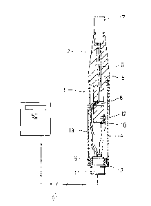
E'ig. 1 is a drawing showing the constitution of
the present invention and a sectional view of a detector;
and
Fig. 2 is a graph showing a relation between
pressure-wise vibration levels obtained by e~periments
and leakage.
DETAILED D~SCRIPTION OF THE PREFFERED h'MBODIMENT:
An example showing an embodiment of the present
invention i9 described below. (See Figs. 1 and 2.)
The whole device consists of a detector 1, an
arithmetic unit 50, and a cable 51 connecting the both
devices. l'he detector 1 is formed by pressing a Eront
end member 2 and a rear end member 3 tight into a
cylindrical body 4.
l'he cylindrical body 4 is covered with a rubber
coating 13 on the outside surface, so that it will be
hard to 91ip during use. The Eitting sections 5 and 6 of
the end members 2 and 3 are provided with spline knurls
to prevent the fall oE the cylindrical body 4.
The upper half section of the front end member
2 is conical while the lower half section is cylindrical
and of smaller diameter than the middle section. There
are provided a longitudinal hole 9 formed from -the top
end through to the center section of the lower cylinder
-- 4
,~...

13~L3~1
and a lateral hole ~ formed across the longitudinal hole.
In the top end are formed internal screw threads, into
which a temperature sensor 7 (temperature measuring
resistor) is screwed. And in the end oE the lower end
section is installed a vibration sensor 10 (piezoelectric
element). This contact surface serves also as the ground
of the vibration sensor.
In the rear end member 3 is screwed a five-pin
connector 11. For internal connection, three conductors
from the temperature sensor passed through in the
aforesaid longitudinal hole 9 and -the lateral hole 8 and
two conductors, one from the vibration sensor and the
other Erom a terminal attached by a screw 12 on the
vibration sensor, are connected to the termina:L of the
connector 11.
An arithmetic unit 50 comprises a functional
section for the proaess oE s.Lgnals Erom the vibration
sensor and temperature sensor of the detector; an
amplifier, an A/D converter: and a display section.
The operation of the whole body o~ the
a~orementioned device i9 as follows. When the
temperature sensor 7 at the top of the detector 1 is
applied to an object to be measured, a temperature signal
is transmitted to the ari-thmetic uni-t 50 directly -through
a conductor and, at the same time, mechanical vibrations
- 5
-:
~-

~3~133~
are transmitted to the vibration sensor 1 through the
fron-t end member 2, being sent as a slgnal to the
arithmetic unit 50.
The arithme-tlc uni-t 50 converts -the signal
coming from the tempera-ture sensor 7, into a saturated
pressure in relation to the temperature measured. Also,
it stores a relation between the vibration level
corresponding to the steam system pressure and the
leakage, shown in the graph of Fig. 2. This graph uses
the pressure as a parameter -to show the relation between
the vibration level and the leakage. As seen from this,
the leakage varies largely (Polnts B, C and D) with the
pressure i~ the vibrations are at the same level (Point
A). Here, the pressure relation is Pl<P3. Erom this
pressure and the vibration leve:L, the steam lealcage is
computed and displayed.
Although the present invention has been fully
described by way of examples with reference to the
accompanying drawings, it is to be noted that various
changes and modifications will be apparent to those
skilled in the art. Therefore, unless otherwise such
changes and modi~ications depart from the scope of the
present invention, they should be construed as included
tberein.

Dessin représentatif
Une figure unique qui représente un dessin illustrant l'invention.
États administratifs

2024-08-01 : Dans le cadre de la transition vers les Brevets de nouvelle génération (BNG), la base de données sur les brevets canadiens (BDBC) contient désormais un Historique d'événement plus détaillé, qui reproduit le Journal des événements de notre nouvelle solution interne.

Veuillez noter que les événements débutant par « Inactive : » se réfèrent à des événements qui ne sont plus utilisés dans notre nouvelle solution interne.

Pour une meilleure compréhension de l'état de la demande ou brevet qui figure sur cette page, la rubrique Mise en garde , et les descriptions de Brevet , Historique d'événement , Taxes périodiques et Historique des paiements devraient être consultées.

Historique d'événement

Description Date
Inactive : Renversement de l'état périmé 2012-12-05
Le délai pour l'annulation est expiré 2009-05-19
Lettre envoyée 2008-05-20
Inactive : CIB de MCD 2006-03-11
Accordé par délivrance 1992-05-19

Historique d'abandonnement

Il n'y a pas d'historique d'abandonnement

Titulaires au dossier

Les titulaires actuels et antérieures au dossier sont affichés en ordre alphabétique.

Titulaires actuels au dossier
TLV CO., LTD.
Titulaires antérieures au dossier
MASAO YONEMURA
Les propriétaires antérieurs qui ne figurent pas dans la liste des « Propriétaires au dossier » apparaîtront dans d'autres documents au dossier.
Documents

Pour visionner les fichiers sélectionnés, entrer le code reCAPTCHA :


Pour visualiser une image, cliquer sur un lien dans la colonne description du document. Pour télécharger l'image (les images), cliquer l'une ou plusieurs cases à cocher dans la première colonne et ensuite cliquer sur le bouton "Télécharger sélection en format PDF (archive Zip)" ou le bouton "Télécharger sélection (en un fichier PDF fusionné)".

Liste des documents de brevet publiés et non publiés sur la BDBC .

Si vous avez des difficultés à accéder au contenu, veuillez communiquer avec le Centre de services à la clientèle au 1-866-997-1936, ou envoyer un courriel au Centre de service à la clientèle de l'OPIC.


Description du
Document 
Date
(aaaa-mm-jj) 
Nombre de pages   Taille de l'image (Ko) 
Abrégé 1993-10-30 1 15
Revendications 1993-10-30 1 28
Page couverture 1993-10-30 1 13
Dessins 1993-10-30 2 39
Dessins représentatifs 2003-03-19 1 7
Description 1993-10-30 7 200
Avis concernant la taxe de maintien 2008-07-02 1 171
Taxes 1997-05-05 1 63
Taxes 1995-05-11 1 58
Taxes 1996-01-17 1 55
Taxes 1993-12-09 1 97