Sélection de la langue

Search

Sommaire du brevet 1301574 

Énoncé de désistement de responsabilité concernant l'information provenant de tiers

Une partie des informations de ce site Web a été fournie par des sources externes. Le gouvernement du Canada n'assume aucune responsabilité concernant la précision, l'actualité ou la fiabilité des informations fournies par les sources externes. Les utilisateurs qui désirent employer cette information devraient consulter directement la source des informations. Le contenu fourni par les sources externes n'est pas assujetti aux exigences sur les langues officielles, la protection des renseignements personnels et l'accessibilité.

Disponibilité de l'Abrégé et des Revendications

L'apparition de différences dans le texte et l'image des Revendications et de l'Abrégé dépend du moment auquel le document est publié. Les textes des Revendications et de l'Abrégé sont affichés :

  • lorsque la demande peut être examinée par le public;
  • lorsque le brevet est émis (délivrance).
(12) Brevet: (11) CA 1301574
(21) Numéro de la demande: 1301574
(54) Titre français: FILTRE POUR SAC DE STOMIE
(54) Titre anglais: FILTER FOR ATTACHMENT TO AN OSTOMY BAG
Statut: Périmé et au-delà du délai pour l’annulation
Données bibliographiques
(51) Classification internationale des brevets (CIB):
  • A61F 05/441 (2006.01)
(72) Inventeurs :
  • STEER, PETER LESLIE (Royaume-Uni)
(73) Titulaires :
  • E.R. SQUIBB & SONS, INC.
(71) Demandeurs :
  • E.R. SQUIBB & SONS, INC. (Etats-Unis d'Amérique)
(74) Agent: OSLER, HOSKIN & HARCOURT LLP
(74) Co-agent:
(45) Délivré: 1992-05-26
(22) Date de dépôt: 1988-03-02
Licence disponible: S.O.
Cédé au domaine public: S.O.
(25) Langue des documents déposés: Anglais

Traité de coopération en matière de brevets (PCT): Non

(30) Données de priorité de la demande:
Numéro de la demande Pays / territoire Date
87 04826 (Royaume-Uni) 1987-03-02

Abrégés

Abrégé anglais


A FILTER OR ATTACHMENT TO AN OSTOMY BAG
ABSTRACT
A three part filter is provided for attachment to an ostomy bag.
One part includes a synthetic plastics base member having a central aperture
and one flat surface whereby the filter can be attached to the bag wall. There
are two walls upstanding from the other side of the base member to define a
channel. The inner wall defines a shallow recess. The second part is a pad of
filtering medium. The third part is a lid member of synthetic plastics material,with apertures through its top wall; the lid being a snug push fit within the
channel. With this arrangement the lid member is readily removable to allow
replacement of the filter pad.

Revendications

Note : Les revendications sont présentées dans la langue officielle dans laquelle elles ont été soumises.


The embodiments of the invention in which an exclusive
property or privilege is claimed are defined as follows:
1. A filter for attachment to an ostomy bag, the
filter comprising three parts, the first part including a
synthetic plastics base member having a central aperture
therein, there being two walls upstanding from the other
side of the base member to define a channel and the inner
wall defining with the base member a shallow recess, the
second part being a pad consisting essentially of a
filtering medium and having a height substantially equal
to that of the recess and lateral dimensions such that it
conforms to and fits snugly within the recess, and the
third part being a lid member of synthetic plastics
material having a substantially flat top, there being a
wall extending from the flat top and having such a
height, shape and width that it is a snug push fit
within the channel, the lid member being capable of being
opened to allow replacement of the said pad; the
synthetic plastics base member having a substantially
flat surface whereby the filter can be attached, by
plastics welding or adhesive, to a wall of an ostomy bag;
characterised in that the filter consists of only three
parts; in that the lid member is provided with apertures
restricted to a peripheral array; in that the radially
inner wall which defines the said channel is chamfered at
its upper, radially outer, region; and in that the filter
and the base member are both of substantially circular
formation.
2. A filter according to claim 1 in which the wall
on the lid member and/or one or both of the walls on the
base member has a projection or a series of projections
whereby a snap fit can be achieved between the base and
lid members.
3. A filter according to claim 1 or claim 2 in which

the wall on the lid member has a radially outwardly
extending rim.

Description

Note : Les descriptions sont présentées dans la langue officielle dans laquelle elles ont été soumises.

~3~P~S'~'~
A ~ILTE~ FOR AT U~C~MENI '11 Al- ns lOMY BA~:
This invention relates to a filter for attachrnent to an ostomy bag~
There has been proposed, in our U.K. Patent Application Serial l\lo.
2177 926, a filter housing forming part of a bag side element of an ostomy
5 coupling. Within this filter housing is received a disc of a filter medium. One
example of a suitable filter element is that disclosed and claimed in our U.K.
Patent Application Serial No. 2171052. While in many circumstances it is
convenient to have a filter housing integral with a bag side coupling element~
for certain kinds of ostomy and similar bags for receiving discharged waste
10 material from the human body, it is desirable to have a filter which is
particularly adapted to be attached to the wall of an ostomy bag. One method
of attachment is the use of an adhesive patch filter and another arrangement is
the employment of a fold-over filter, see our U.K~ Patent 2122 090. In
contrast to these suggestions, the present invention aims to meet the need For a15 filter which can be permanently attached to the bag but which nevertheless
permits exchanging the filter medium.
According to the present invention, there is provided a filter for
attachment to an ostomy bag and which comprises three parts, the first part
including a synthetic plastics base member having a central aperture therein
20 and one substantially Flat surface whereby the filter can be attached by plastics
welding or adhesive to a wall of the ostomy bag, there being two walls
upstanding from the other side of the base member to define a channel and the
inner wall def ining with the base member a shallow recess, the second part
being a pad consisting essentially of a filtering medium and having a height
25 substantially equal to that of the recess and lateral dimensions such that it fits
snugly within the recess, and the third part being a lid member of synthetic
plastics material having a substantially flat top through which are pro~tided a
peripheral array of apertu~es, there being a wall extending from the flat top
and having such a height, shape and width that it is a snug push fit within the
30 channel; whereby the lid member is readily removable to allow replacement of
the said pad.

~3~ J
In a preferred embodiment of the invention the channel and the wall
on the lid member are of substantially circular formation.
In an advantageous embodiment of the invzntion, the wall on the lid
member and/or one or both of the walls on thR base member has a projection or
a series of projections. These projections are positioned and dimensioned such
that a snap fit can be achieved between the base and the lid members, and such
that these members can be separated manually quite readily by the wearer.
In a particularly preferred embodiment of the invention, the lid
member has a circular array of apertures located adjacent to and interiorly of
the wall thereon, said wall being substantially cylindrical in shape so as to
define a shallow cylindrical recess for receiving the filter medium in the form of
a disc.
The wall on the lid member may have a radially outwardly extending
rim so as to enhance its snap fit co-operation with the aforesaid channel.
The invention will be better understood from a consideration of the
following description of an illustrative embodiment thereof, given with
reference to the accompanying drawings, in which:-
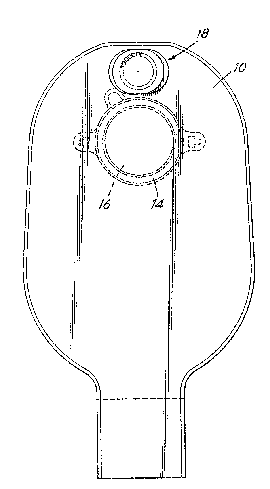
Figure 1 is a front view of an ostomy bag including a filter in
accordance with one example of the present invention;
Figure 2 is a diagrammatic side view of the ostomy bag shown in
Figure l;
Figure 3 is a front view of the base member of an example of filter
in accordance with the present invention;
Figure 4 is a cross-sectional view on a line 4-4 in Figure 3 of the
base member;
Figure 5 and Figure 6 are respectively a front view and a side view
of a filter pad for use in a filter according to the present invention;
Figure 7 is a front view of a lid member for use in a filter according
- to the present invention;
Figure 8 is a rear view of the lid member shown in Figure 7, and
Figure 9 is a cross-sectional view on the lines IX-IX of Figures 7 and
8~

~3~
The illustrated ostomy bag has a front wall 10 and a rear wall 12.
Front and rear are used in the context of a forward facing person wearing an
ostomy bag on a forward part of his abdomen. The rear wall 12 of the ostomy
bag carries a bag side ostomy coupling. This is intendPd to co-operate with a
5 body side coupling in a manner now well known in the art, see for example
British Patent 1571657. The bag side coupling is shown at 14. It surrounds a
stomal aperture 1~ in the wall of the bag. The front wall 10 carries a filter 18in accordance with the present invention. Datails of the filter will be better
understood frorn Figures 3~9.
The filter includes a first part or base member 20, a filter pad 30,
and a lid member or third part 40.
The base member 20 is of synthetic plastics material and has a
central aperture 21 therein and one substantially flat surface 22 whereby the
filter can be attached by plastics welding or adhesive to the wall 10 of the
15 ostomy bag.
Two walls 23, 24 are upstanding from the other side 25 of the base
member to define a channel 26 therebetween. The inner wall defines with the
base member a shallow recess 27. In the illustrated embodiment of the
invention, the walls 23 and 24 are generally circular and the recess is of a
20 shallow cylindrical shape. However, the advantages of the invention do not
necessarily require a circular configuration for the walls and a cylindrical
recess, other shapes may be employed as will be understood by a man of
average skill in the art. The outer wall 24 as seen in Figure 4, has an internalperipheral rim or projection 28.
The second part shown in Figures 5 and 6 is a filter pad of suitable
material which permits a passage of gases. It may carry activated carbon as
filter material. Any known suitable filter pad or disc may be employed but a
particularly advanSageous one is that disclosed and claimed in our 8ritish
Patent Application Serial No. 2171052.
The third part of the illustrated filter according to the present
invention is the lid member 40, and this has a generally flat lid portion 42 and a
cylindrical wall 44 extending therefrom. It also has a series of apertures 46
arranged to provide a plurality of peripherally arranged exit paths for fiitered

:~3~ 7~
gas to pass to the exterior. These apertures are shown at 46. As illustrated,
the wall 44 has a peripheral external rim or projection 48 at its end further
from the lid portion 42. The projection 48 is pushed past the projection 28 on
the wall 24 when the wall 44 is inserted into the channel 26 as occurs when the
5 lid is placed on the base member. The presence of the projections described
gives a secure attachment of the lid to the base member but ne~ertheless this
construction is an arrangement in which an easy manual separation of these two
parts can be obtained, e.g. when it is desired to change the filter disc in the
recess 27.

Dessin représentatif
Une figure unique qui représente un dessin illustrant l'invention.
États administratifs

2024-08-01 : Dans le cadre de la transition vers les Brevets de nouvelle génération (BNG), la base de données sur les brevets canadiens (BDBC) contient désormais un Historique d'événement plus détaillé, qui reproduit le Journal des événements de notre nouvelle solution interne.

Veuillez noter que les événements débutant par « Inactive : » se réfèrent à des événements qui ne sont plus utilisés dans notre nouvelle solution interne.

Pour une meilleure compréhension de l'état de la demande ou brevet qui figure sur cette page, la rubrique Mise en garde , et les descriptions de Brevet , Historique d'événement , Taxes périodiques et Historique des paiements devraient être consultées.

Historique d'événement

Description Date
Inactive : Renversement de l'état périmé 2012-12-05
Le délai pour l'annulation est expiré 2009-05-26
Lettre envoyée 2008-05-26
Accordé par délivrance 1992-05-26

Historique d'abandonnement

Il n'y a pas d'historique d'abandonnement

Titulaires au dossier

Les titulaires actuels et antérieures au dossier sont affichés en ordre alphabétique.

Titulaires actuels au dossier
E.R. SQUIBB & SONS, INC.
Titulaires antérieures au dossier
PETER LESLIE STEER
Les propriétaires antérieurs qui ne figurent pas dans la liste des « Propriétaires au dossier » apparaîtront dans d'autres documents au dossier.
Documents

Pour visionner les fichiers sélectionnés, entrer le code reCAPTCHA :


Pour visualiser une image, cliquer sur un lien dans la colonne description du document (Temporairement non-disponible). Pour télécharger l'image (les images), cliquer l'une ou plusieurs cases à cocher dans la première colonne et ensuite cliquer sur le bouton "Télécharger sélection en format PDF (archive Zip)" ou le bouton "Télécharger sélection (en un fichier PDF fusionné)".

Liste des documents de brevet publiés et non publiés sur la BDBC .

Si vous avez des difficultés à accéder au contenu, veuillez communiquer avec le Centre de services à la clientèle au 1-866-997-1936, ou envoyer un courriel au Centre de service à la clientèle de l'OPIC.

({010=Tous les documents, 020=Au moment du dépôt, 030=Au moment de la mise à la disponibilité du public, 040=À la délivrance, 050=Examen, 060=Correspondance reçue, 070=Divers, 080=Correspondance envoyée, 090=Paiement})


Description du
Document 
Date
(aaaa-mm-jj) 
Nombre de pages   Taille de l'image (Ko) 
Abrégé 1993-10-29 1 33
Revendications 1993-10-29 2 45
Dessins 1993-10-29 3 59
Dessins représentatifs 2003-03-11 1 11
Description 1993-10-29 4 136
Avis concernant la taxe de maintien 2008-07-06 1 171
Taxes 1996-04-16 1 65
Taxes 1994-02-23 1 32
Taxes 1997-04-16 1 96
Taxes 1995-04-20 1 67