Note : Les descriptions sont présentées dans la langue officielle dans laquelle elles ont été soumises.
l BACKGROUND OF THE INVENTION
Field of the Invention
This invention relates to a method and assembly for
producing extruded permanent magnet articles from particle
charqes of permanent magnet alloys.
BRIEF DESCRIPTION OF THE D~AWINGS
Fig. 1 shows a conventional assembly of permanent magnet
segments in association with a motor shaft;
Fig. 2 shows a conventional assembly of a motor shaft and an
associated cylindrical permanent magnet;
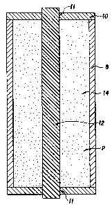
Fig. 3 shows in veLtical cross-section an embodiment of an
assembly in accordance with the invention for use in the method
thereof to produce an extruded magnet; and
Fig. 4 is a top view of the assembly of Fig. 3.
t5 Description of the Prior Art
It is known to produce permanent magnet articles by powder
metallurgy techniques, which include the consolidation of
particles of the permanent magnet alloys. These practices are
employed with permanent magnet alloys of at least one rare earth
element and transistion element. These conventional practices
generally include the steps of aligning, pressing and sintering.
With prior art practices of this type, high energy product
~BHmaX) and uniaxial anisotropic crystal alignment is achieved,
and this combination finds utility in various permanent magnet
applications.
Uniaxial anisotropic crystal alignment, however, is not
always advantageous for magnet applications for rotating
l machinery, motor rotors, beam focusing devices and the like. For
these applications a [lOO] fiber texture wherein the C
crystallographic axis is perpendicular to the axis of the magnet
may be desired. One of the primary applications for magnets of
S this construction is for use in DC motors. In this application,
with conventional practice, multiple segments of uniaxial
anistropic magnets are needed to form the armature for the motor,
which segments are identified as 2 positioned around a motor
shaft 4 in Fig. l.
To obviate the need for the use of a plurality of magnet
segments, as shown in Fig. 1, it is known to extrude a
cylindrical magnet conforming to the required dimensions of the
motor shaft. An extruded magnet 6 in association with a motor
shaft 4 is shown in Fig. 2.
Cylindrical, extruded magnets, as shown in Fig. 2, are
conventionally produced by the use of a cylindrical extrusion
container. Magnet alloy particles are introduced to the
container, and the container is outgassed, evacuated and sealed.
Thereafter, the container is heated to extrusion temperature and
extruded to consolidate the particles to substantially full
density. The hollow center of the magnet is achieved by the use
of a solid cylinder or mandrel of a diameter corresponding to the
internal diameter of the magnet to be produced, which cylinder is
attached to the extrusion ram. This solid cylinder moves with
the extrusion ram during the extrusion operation and thereby
maintains the desired inner diameter of the extruded magnet. It
is difficult to maintain concentricity of the inner and outer
peripheries of the extruded magnet because the mandrel tends to
-- 2 --
:~q~
wander and thus is not maintained in axial alignment during the
extrusion operation. In addition, at the high extru~ion ratios
breaking of the mandrel may occur. It may be seen, there~ore,
that in producing cylindrical magnets by conventional extrusion
practices, a cylindrical magnet having the required concentric
dimensions is difficult to achieve.
OBJECTS AND SUMMARY OF THE INVEMTION
It i5 accordingly a primary object of the present invention
to provide an extrusion method and assembly for use therewith
that achieves improved concentricity in the production of
extruded hollow cylindrical magnets.
A more specific object of the invention is a method and
assembly for use therewith that enables the production of a
complete assembly, including a permanent magnet and associated
1~ shaft in a single extrusion operation.
Broadly, in accordance with the method of invention for
producing a compacted fully dense permanent magnet article, a
particle charge is provided of a permanent magnet alloy
composition from which the permanent magnet artlcle ls to be
made. The particle charge is placed in a cylindrical con~ainer
having a generally axially po~itioned core with the charge
surrounding the core within the container. The container is
evacuated and sealed against the atmosphere. The container and
particle charge are heated to elevated temperature and the
container and charge are then extruded to compact the charge to
substantially full density to thereby produce a substantially
fully dense permanent magnet article.
,, ~
,
l ~t31 ~()2
To facilitate removal of the core to produce the desired
cylindrical magnet article, a separating medium, such as
magnesium oxide, may be provided on the core. The core may be of
carbon steel, a soft magnet material or stainless steel. ~uring
the extrusion operation, the core may be bonded to the permanent
magnet alloy. This is advantageous from the standpoint of
producing a unitary magnet and shaft assembly during the
extrusion operation.
Extrusion ratios within the range of l.S:l to 50:1 may be
employed with extrusion temperatures within the range of 500 to
1200C.
The method of the invention finds particular use in
producing rare earth element containing permanent magnets. More
specifically, it may be used in the production of magnets of this
type wherein at least one rare earth element, such as samarium,
neodymium and dysprosium, may be used with a transition element,
such as iron and cobalt, plus boron andtor carbon.
The invention for use in producing a compacted, fully dense
permanent magnet article by extrusion includes a cylindrical
container having a core generally axially positioned therein.
The mandrel defines an annular chamber within the container. A
particle charge of a permanent magnet alloy from which the
article is to be made is provided within this annular chamber.
Means are provided for sealing the annular chamber.
A separating medium may be provided on the core. This
facilitates removal of the core from the compacted magnet after
extrusion. The core may be constructed of carbon steel, a soft
magnet material or stainless steel.
- 4 -
.,..., .,~
1 DETAILED D~SCRIPTION OF THE PREFERRED EMBODIMENTS
In accordance with one embodiment of the invention, with
reference to Figs. 3 and 4, there is shown a cylindrical
container 8 having end plates 10 with axial openings 11 connected
at opposite ends of the container, as by welding (not shown) to
seal the container. A solid core 12 is connected at opposite
ends thereof to the plates 10 and a portion extends through
openings 11. The core is axially positioned within the container
8 to define therein an annular chamber 14 surrounding the core.
Particles F of the magnet alloy composition from which the magnet
is to be constructed are provided within the annular chamber 14
of the container 8.
The assembly of Figs.3 and 4 so constructed is then after
outgassing heated to extrusion temperature and extruded in
conventional extruding apparatus to compact the particles in the
container to substantially full density. Thereafter, the core 12
may be removed from the compacted hollow cylindrical magnet.
This may be faclitated by having the core provided with a
separating medium, such as magnesium oxide, on the surface
2~ thereof. Alternately, the core may be bonded to the cylindrical
A
~3~?lf~
1 magnet for use as an assembly in the production of a conventional
motor rotor, as shown in Fig. 2.
Example 1
A carbon steel extrusion container was made with a solid
low-carbon rod, 3/4~ in diameter, welded axially to the top and
bottom plates of a mild carbon steel can. Atomized
(NdDy)l5Fe79B6 powder was put into the 3-1/8~ diameter can and
the can was heated to 150C, evacuated and sealed. The container
was then heated to 927C and extruded with a ratio of 13.8:1.
The final extrusion consisted of a 0.3~ diameter steel rod
surrounded by a ring shaped magnet with a wall thickness of about
0.25~. The magnetic properties are listed in Table 1. The
identical properties along two orthogonal directions
perpendicular to the extrusion direction indicates that a [100]
fiber texture is obtained. This is the same magnetic behavior as
is observed for magnets extruded by conventional methods.
These extruded magnets, with rods at their centers, can
directly be magnetized into multiple poles and used for any type
of rotating assembly.
TABLE 1
Sample Test Br Hc Hci BHmax
Desiqnation Direction kG kOe kOe MGOe
EX-267 Axial 3.8 3.3 15.3 3.1
Transverse 1 7.3 6.4 15.8 12.3
Transverse 2 7.2 6.3 15.7 11.6
Example 2
To compare the practice of Example 1 with a conventional
, ~ ,
practice, the identical powder used in Example 1, (NdDy)15Fe79B6,
1 was placed into a 3-l/8~ diameter can and the can was heated to
150C, evacuated and sealed. The can was then heated to 927C
and extruded with a ratio of 13.8:1. The magnetic properties of
the resultant solid cylinder are presented in Table II. The
magnetic properties are very similar to those obtained in Example
1. Thus, the extrusion technique of Example l in accordance with
the invention will produce magnetic properties comparable to a
conventional magnet extrusion method.
TABLE II
Sample Test Br Hc Hci ~Hmax
Desi~nation Direction kG kOe kOe MGOe
EX-235 Axial 3.6 3.1 13.9 2.7
Transverse 1 7.1 6.1 14.0 10.9
Transverse 2 7.1 6.1 14.1 11.0
ExamPle 3
The same powder as used in Examples 1 and 2 was placed in a
carbon steel extrusion container. This extrusion container was
in the shape of a hollow circular cylinder, 3-1/8~ OD and 3~4~
ID. The container was evacuated, sealed and heated to 927C and
extruded at a 10:1 extrusion ratio. The inner diameter was
maintained during extrusion by affixing a solid mandrel to the
ram of the extrusion press in accordance with conventional
practice. The magnetic properties, Table III, are similar to the
properties presented in Tables I and II. The concentricity
defined as the ratio of minimum to maximum wall thickness, was
calculated to be 0.90. This value is poorer than the
concentricit~, 0.95, measured on the sample extruded in Example 1
in accordance with the invention.
-7-
13-~161)Z
1 Table III
Sample Test Br Hc Hci BHmax
Desiqnation Dire tion kG kOe kOe MGOe
EX-261 Axial 3.5 3.0 14.4 2.6
Transverse 7.4 6.5 16.5 12.4
As may be seen from the above descriptions and Examples, the
invention provides for the production of a hollow permanent
magnet by an extrusion practice wherein the desired dimensions of
the magnet may be maintained while achieving permanent magnet
properties comparable to conventional practices used for this
purpose.
It is to be understood that the shape of the core may
include symmetrical geometries other than cylindrical. The
particles of magnetic material for compaction may be produced by
atomization, rapidly solidified ribbon, cast and pulverized
particles, direct cast ingots or particles made by a
reduction-diffusion practice.
Since the core may be bonded to the compacted magnet during
extrusion, an assembly may be produced having an outer shell of a
permanent magnet alloy and a soft magnetic inner core, with the
inner core acting to direct magnetic flux.
-8-