Sélection de la langue

Search

Sommaire du brevet 1302811 

Énoncé de désistement de responsabilité concernant l'information provenant de tiers

Une partie des informations de ce site Web a été fournie par des sources externes. Le gouvernement du Canada n'assume aucune responsabilité concernant la précision, l'actualité ou la fiabilité des informations fournies par les sources externes. Les utilisateurs qui désirent employer cette information devraient consulter directement la source des informations. Le contenu fourni par les sources externes n'est pas assujetti aux exigences sur les langues officielles, la protection des renseignements personnels et l'accessibilité.

Disponibilité de l'Abrégé et des Revendications

L'apparition de différences dans le texte et l'image des Revendications et de l'Abrégé dépend du moment auquel le document est publié. Les textes des Revendications et de l'Abrégé sont affichés :

  • lorsque la demande peut être examinée par le public;
  • lorsque le brevet est émis (délivrance).
(12) Brevet: (11) CA 1302811
(21) Numéro de la demande: 1302811
(54) Titre français: ECHANGEUR DE CHALEUR
(54) Titre anglais: HEAT EXCHANGER
Statut: Périmé et au-delà du délai pour l’annulation
Données bibliographiques
Abrégés

Abrégé anglais


- 10 -
HEAT EXCHANGER
ABSTRACT OF THE DISCLOSURE
A fuel pre-heater is used for heating the fuel for inter-
nal combustion engines, especially diesel engines. The
pre-heater has an elongate cylindrical outer container
housing an inner, concentric tube so as to provide an
annular chamber between the two. A fuel tube, formed into
a coil extends the length of the annular chamber, with its
inlet and outlet exiting through the ends of the con-
tainer. Heating medium inlet and outlet nipples for the
container are arranged tangentially, at opposites ends of
the container and oriented in opposite directions. The
heating medium inlet and outlet are connected into the
coolant system of the internal combustion engine while the
fuel inlet and outlet are connected into the fuel line
leading to the fuel injectors or carburetor of the engine.
The pre-heater produces with its long path and counterflow
pattern highly efficient heat transfer from the cooling
medium to the fuel.

Revendications

Note : Les revendications sont présentées dans la langue officielle dans laquelle elles ont été soumises.


- 8 -
CLAIMS:
1. A fuel pre-heater comprising:
a container with a cylindrical outer wall and
closed ends;
an inner cylindrical wall extending from end to
end of the container, concentrically therein to provide
an annular chamber within the container;
a tube formed into a helical coil located
between the inner and outer walls, with ends of the tube
extending through the container to the exterior thereof,
adjacent opposite ends of the container; and
inlet and outlet fittings connected to the
cylindrical outer wall, to open in opposite tangential
directions into the annular chamber adjacent opposite
ends thereof.
2. A pre-heater according to Claim 1 wherein the
coil is located substantially midway between the inner
and outer walls.
3. A pre-heater according to Claim 1 wherein the
diameter of the tube is substantially one-half the radial
distance between the inner and outer walls.
4. A pre-heater according to Claim 1 wherein the
ends of the coil project through the ends of the
container.

- 9 -
5. A pre-heater according to Claim 1 wherein the
coil is wound to intercept fluid flowing tangentially
into the inlet fitting and to direct the flow into a
helical path leading towards the outlet.

Description

Note : Les descriptions sont présentées dans la langue officielle dans laquelle elles ont été soumises.

~3t~2~
-- 1 --
HEAT EXCHANGER
FIELD OF THE INVENTION
The present invention relates to a heat
exchanger for pre-heating fuel with a heated liquid.
BACKGROUND
Cold ambient temperatures frequently cause
problems in the operation of internal combustion engines,
especially diesel engines. It is known that pre-heating
the fuel for such an engine, either before carburetion or
in~ection, is useful in improving operation and engine
fuel economy. Various fuel pre-heaters for pre-heating
fuel using hot coolant from the engine cooling system have
been proposed. In general, a fuel heat exchanger of this
type could be of various designs, however size and weight
have become a restrictive factor in the engine compart-
ments of newer vehicles. It therefore becomes important
to reduce these physical parameters and to imprGve the
efficiency of the heat transfer in such a unit. The
present invention aims at such improvements.
SUMMARY
According to the present invention, there is
provided a fuel pre-heater comprising:
a container with a cylindrical outer wall and
...

~3'32811
closed ends;
an inner cylindrical wall extending from end to
end of the container, concentrically therein to provide an
annular chamber within the container;
a tube formed into a helical coil located
between the inner and outer walls, with ends of the tube
eXtending through the container to the exterior thereof,
adjacent opposite ends of the container; and
inlet and outlet fittings connected to the
cylindrical outer wall, to open in opposite tangential
directions into the annular chamber adjacent opposite ends
thereof.
In preferred embodiments, the ends of the coil
extend through the end walls of the container and the
spacing between the coil and the inner and outer walls is
kept to a minimum. Fuel is passed through the coil in
counter flow to hot engine coolant passing through the
annular chamber between the inner and outer walls.
A fuel heat exchanger so constructed has a
number of significant characteristics. The tangential
inlet and outet for heating medium cause the heating
medium to flow helically through the annular chamber to
provide the maximum length of heat transfer path. This
provides the highest possible log mean temperature

~3~2811
difference. The fuel outlet temperatures have been found
to approach the inlet temperatures of the heating medium
to within 15F (8.3C), which compares favourably with the
35~F (19.4C) temperature difference observed with axial
heat medium connections.
The inner wall forces the heating medium into
the annular spacing to maximize contact between the
heating medium and the fuel coil. By minimizing the
clearance between the coil and the inner and outer walls,
the flow is forced into a helical flow pattern inhibiting
axial flow along the walls. In addition, the thin film of
heating medium thus produced has been found to transfer
its heat content more readily than a thicker film. The
thin film flow also has a high velocity that is expected
to retain solids in suspension, thus minimizing sediment
build-up in the heat exchanger.
BRIEF DESCRIPTION OF THE DRAWINGS
In the accompanying drawings, which illustrate
an exemplary embodiment of the present invention:
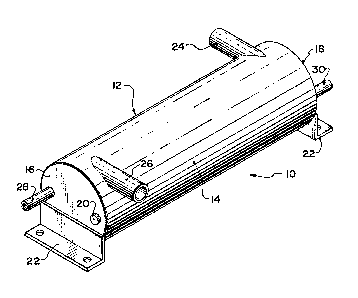
Figure 1 is an isometric view of a fuel heat
exchanger according to the present invention;
Figure 2 is a side elevation with the outer wall
shown in section of the heat exchanger in Figure l; and
Figure 3, found on the same strut as Figure 1,

13(~2811
is a schematic view of the connections of the heat
exchanger to an internal combustion engine.
DETAILED DESCRIPTION
Referring to the accompanying drawings, and
particularly to Figures 1 and 2, there is illustrated a
heat exchanger 10 that is housed within a container 12
defined by a cylindrical outer wall 14 and two circular
end walls 16 and 18. The end wall 16 has a clean out and
bleed opening closed by a plug 20. Two mounting brackets
22 of L-shape are mounted on the respective ends 16 and
18. The cylindrical outer wall 14 of the container 12 is
fitted with tangential inlet and outlet nipples 24 and 26
respectively. The lnlet nipple 24 is located adjacent the
end 18, while the outlet nipple 26 is located adjacent the
end 16. The two nipples project in opposite tangential
directions from the container.
A fuel inlet tube 28 projects through the end 16
of the container 12, adjacent the periphery of the wall,
while a fuel outlet 30 pro;ects through the end 18, also
ad;acent the periphery of that wall. The inlet and outlet
28 and 30 are the opposite ends of a fuel tube 32 that is
formed into a coil 34 inside the container 12. The coil
34 surrounds an inner, concentric tube 36 that extends
between the ends 16 and 18 of the container 12, concentri-

~3(~Z8~
cally with the cylindrical outer wall 14. The tube 36defines an inner wall 38 of an annular chamber 40 between
the inner and outer walls 38 and 14 respectively.
In use, fuel is supplied to the fuel inlet 28 to
flow internally through the helical coil 34 to the fuel
outlet 30. A heating medium such as engine coolant, is
supplied to the annular chamber 40 through the tangential
inlet 24. The tangential flow is confined in the annular
chamber 40 and is caused by the helical coil 34 to flow in
a helical path, following the coil to the outlet 26 at the
opposite end of the heat exchanger. The flow of the
heating medium and that of the fuel in the coil 34 are in
counterflow, and have been found to be very efficient with
respect to its heat transfer. The presently preferred
diameter of the fuel tube 32 forming the coil 34 is about
one-half the radial distance between the inner wall 38 and
the outer wall 14. This promotes the helical flow of the
heating medium in the annular chamber and inhibits the
flow of heating medium along the inner or outer walls
directly from the inlet to the outlet.
Figure 3 illustrates the use of the heat
exchanger in connection with an internal combustion engine
42. The engine has a coolant pump 44 that pumps the
engine coolant from the radiator 48 through a line 46 to

13UZ811
the low water iacket 66 of the engine 42. A line 50
allows hot engine coolant to flow from the high water
jacket 65 to the top of the radiator 48 when the engine
thermostat is in the open position. A hot coolant line 52
leads from the high water jacket 65 of the engine 42 to
the heating medium inlet 24 of the heat exchanger 10. A
second coolant return line 54 leads from the outlet 26 of
the heat exchanger 10 to the suction side of the water
pump 44. A fuel tank 56 is connected to a fuel line 58
leading to the fuel inlet 28 of the heat exchanger 10,
while a further fuel line 60 leads the heated fuel from
the heat exchanger 10 to a fuel filter 63. From the fuel
filter 63 a fuel line 64 leads the heated fuel to a
schematically illustrated fuel atomizing device 62 of the
engine 42 which may be a carburetor or a set of fuel
injectors. The heat exchanger 10 may also be installed
after the fuel filter 63 and before the atomizing device
62. A return line 59 from the atomizing device to the
fuel tank 56 supplies excess warm fuel to the fuel tank to
prevent gelling in cold weather.
In the foregoing, a single embodiment of the
present invention has been described. It is to be under-
stood however, that other embodiments are possible within

13~Z811
-- 7 ~
the scope of the invention, and that the invention is to
be considered limited solely by the scope of the appended
claims.

Dessin représentatif
Une figure unique qui représente un dessin illustrant l'invention.
États administratifs

2024-08-01 : Dans le cadre de la transition vers les Brevets de nouvelle génération (BNG), la base de données sur les brevets canadiens (BDBC) contient désormais un Historique d'événement plus détaillé, qui reproduit le Journal des événements de notre nouvelle solution interne.

Veuillez noter que les événements débutant par « Inactive : » se réfèrent à des événements qui ne sont plus utilisés dans notre nouvelle solution interne.

Pour une meilleure compréhension de l'état de la demande ou brevet qui figure sur cette page, la rubrique Mise en garde , et les descriptions de Brevet , Historique d'événement , Taxes périodiques et Historique des paiements devraient être consultées.

Historique d'événement

Description Date
Le délai pour l'annulation est expiré 1999-06-09
Lettre envoyée 1998-06-09
Accordé par délivrance 1992-06-09

Historique d'abandonnement

Il n'y a pas d'historique d'abandonnement

Historique des taxes

Type de taxes Anniversaire Échéance Date payée
Annulation de la péremption réputée 1997-06-09 1997-05-28
TM (catégorie 1, 5e anniv.) - petite 1997-06-09 1997-05-28
Titulaires au dossier

Les titulaires actuels et antérieures au dossier sont affichés en ordre alphabétique.

Titulaires actuels au dossier
UNIVERSAL DIESEL PRODUCTS INC.
Titulaires antérieures au dossier
GORDON BRIDGEMAN
Les propriétaires antérieurs qui ne figurent pas dans la liste des « Propriétaires au dossier » apparaîtront dans d'autres documents au dossier.
Documents

Pour visionner les fichiers sélectionnés, entrer le code reCAPTCHA :


Pour visualiser une image, cliquer sur un lien dans la colonne description du document. Pour télécharger l'image (les images), cliquer l'une ou plusieurs cases à cocher dans la première colonne et ensuite cliquer sur le bouton "Télécharger sélection en format PDF (archive Zip)" ou le bouton "Télécharger sélection (en un fichier PDF fusionné)".

Liste des documents de brevet publiés et non publiés sur la BDBC .

Si vous avez des difficultés à accéder au contenu, veuillez communiquer avec le Centre de services à la clientèle au 1-866-997-1936, ou envoyer un courriel au Centre de service à la clientèle de l'OPIC.


Description du
Document 
Date
(aaaa-mm-jj) 
Nombre de pages   Taille de l'image (Ko) 
Abrégé 1993-10-30 1 24
Dessins 1993-10-30 2 56
Revendications 1993-10-30 2 28
Description 1993-10-30 7 166
Dessin représentatif 2002-01-29 1 16
Avis concernant la taxe de maintien 1998-07-06 1 179
Taxes 1996-08-01 1 39
Taxes 1995-06-01 1 37
Taxes 1994-04-06 1 36