Sélection de la langue

Search

Sommaire du brevet 1303479 

Énoncé de désistement de responsabilité concernant l'information provenant de tiers

Une partie des informations de ce site Web a été fournie par des sources externes. Le gouvernement du Canada n'assume aucune responsabilité concernant la précision, l'actualité ou la fiabilité des informations fournies par les sources externes. Les utilisateurs qui désirent employer cette information devraient consulter directement la source des informations. Le contenu fourni par les sources externes n'est pas assujetti aux exigences sur les langues officielles, la protection des renseignements personnels et l'accessibilité.

Disponibilité de l'Abrégé et des Revendications

L'apparition de différences dans le texte et l'image des Revendications et de l'Abrégé dépend du moment auquel le document est publié. Les textes des Revendications et de l'Abrégé sont affichés :

  • lorsque la demande peut être examinée par le public;
  • lorsque le brevet est émis (délivrance).
(12) Brevet: (11) CA 1303479
(21) Numéro de la demande: 1303479
(54) Titre français: PORTE
(54) Titre anglais: DOOR
Statut: Périmé et au-delà du délai pour l’annulation
Données bibliographiques
(51) Classification internationale des brevets (CIB):
  • E05D 15/16 (2006.01)
  • E05D 1/04 (2006.01)
  • E05D 15/24 (2006.01)
  • E06B 9/13 (2006.01)
(72) Inventeurs :
  • RUITER, MARK ANDRE
(73) Titulaires :
  • POLYNORM N.V.
(71) Demandeurs :
(74) Agent: SMART & BIGGAR LP
(74) Co-agent:
(45) Délivré: 1992-06-16
(22) Date de dépôt: 1989-09-22
Licence disponible: S.O.
Cédé au domaine public: S.O.
(25) Langue des documents déposés: Anglais

Traité de coopération en matière de brevets (PCT): Non

(30) Données de priorité de la demande:
Numéro de la demande Pays / territoire Date
88.02968 (Pays-Bas (Royaume des)) 1988-12-01

Abrégés

Abrégé anglais


ABSTRACT
A door comprising a flexible panel of flexible
profile plate material which is guided around guide means
from a closing position to an opened position is especially
intended for closing garages.
In order to enlarge the height clearance in the
opened position of the door the flexible panel assumes a
substantially lying position in the opened state.

Revendications

Note : Les revendications sont présentées dans la langue officielle dans laquelle elles ont été soumises.


4 21766-557
THE EMBODIMENTS OF THE INVENTION IN WHICH AN EXCLUSIVE
PROPERTY OR PRIVILEGE IS CLAIMED ARE DEFINED AS FOLLOWS:
1. A door assembly for a vertical doorway opening
comprising:
a door movable between an open position and a closed
position, said door comprising a flexible door panel having two
opposed side edges and a lower horizontal panel edge, said
flexible door panel being substantially horizontal in the open
position and bendable along its horizontal axis;
guide means for guiding said flexible door panel as it moves
between a closed position and an open position, said guide means
comprising a pair of opposed rotatable guide wheels near the top
of each side of said doorway opening, the perimeters of said
rotatable guide wheels contacting an inner surface of said
flexible door panel near each of its two opposed side edges
whereby said flexible door panel bends along its horizontal axis
as the portions of the two opposed side edges contact the
perimeter of said rotatable guide wheels, and said guide means
further comprising a vertical U-shaped frame extending downward
from each of said rotatable guide wheels along each side of said
doorway opening for slidably engaging the opposed side edges of
the flexible door panel; and
a horizontal strengthening strip pivotally connected to the
lower horizontal panel edge of the flexible door panel, said lower
horizontal panel edge being attached to an edge strip and said
edge strip being pivotally engaged to the horizontal strengthening
strip; and
means for limiting the pivotal rotation between the

21766-557
horizontal strengthening strip and the edge strip to a
predetermined angle of rotation.
2. The door assembly according to claim 1, wherein a lower
portion of the horizontal strengthening strip has a substantially
S-shaped cross-sectional profile.
3. The door assembly according to claim 1, wherein a lower
portion of the horizontal strengthening strip has a substantially
S-shaped cross-sectional profile.
4. The door assembly according to claim 3, wherein an upper
portion of the horizontal strengthening strip has a gripping edge
for pivotally engaging said edge strip.
5. The door assembly according to claim 1 further including
a guide member extending from each end of the horizontal
strengthening strip, and a stationary guide means at each side of
said doorway opening near the top of said U-shaped side frame
which cooperates with said guide member for guiding the opposed
side edges of the flexible door panel into engagement with said
vertical U-shaped side frames as the door is moved from the open
position to the closed position.
6. The door assembly according to claim 1, further
including guide strips on an inner surface of the flexible door
panel along each of the opposed side edges of the flexible door
panel for contacting the perimeter of the rotatable guide wheels.

6 21766-557
7. The door assembly according to claim 6, wherein each
guide strip comprises a plurality of ridges extending from an
inner surface of said flexible door panel and each rotatable guide
wheel includes corresponding notches in its perimeter for engaging
said ridges of the guide strip.
8. The door assembly according to claim 1, wherein the
flexible door panel is composed of a single sheet of metal.

Description

Note : Les descriptions sont présentées dans la langue officielle dans laquelle elles ont été soumises.

~3~ 7~
1 21766-557
The invention relates to a door comprislng a flexible
panel of flexible profile plate material which is guided around
guide means from a closing position to an opened position.
Such a door is known and is especially, but not
exclusively, intended for closing garages. It can be of
importance here that in the opened position the door leaves clear
the greatest possible height, in order for example to allow
passage of the highest possible vehicles.
The invention has for its object to enlarge the height
clearance in the opened position while ensuring that the door
operates without difficulty.
The invention provides a door assembly for a vertical
doorway opening comprising: a door movable between an open
position and a closed position, said door comprising a flexible
door panel having two opposed side edges and a lower horizontal
panel edge, said flexible door panel being substantially
horizontal in the open position and bendable along its horizontal
axis; guide means for guiding said flexible door panel as it moves
between a closed position and an open position, said guide means
comprising a pair of opposed rotatable guide wheels near the top
of each side of said doorway opening, the perimeters of said
rotatable guide wheels contacting an inner surface of said
flexible door panel near each of its two opposed side edges
whereby said flaxible door panel bends along its horizontal axis
as the portions of the two opposed side edges contact the
perimeter of said rotatable guide wheels, and said guide means
further comprising a vertical U-shaped frame extending downward
from each of said rotatable guide wheels along each side of said

~3~
la 21766-557
doorway opening for slidably engaging the opposed side edges of
the Elexible door panel; and a horizontal strengthening strip
pivotally connected to the lower horizontal panel edge of the
flexible door panel, said lower horizontal panel edge being
attached to an edge strip and said edge strip being pivotally
engaged to the horizontal strengthening strip; and means for
limiting the pivotal rotation between the horizontal strengthening
strip and the edge strip to a predetermined angle of rotation.
The foregoing and other features of the invention will
be elucidated in the description following hereinafter with
reference to the accompanying schematic drawing wherein: -
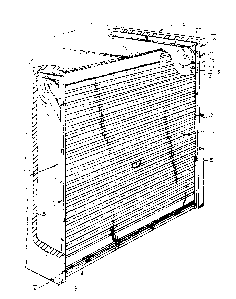
Figure 1 shows a partly broken away perspective view of
a garag~ with a door according to the invention;
Figure 2 shows on a larger scale a perspective view of
fraction II of Figure l;

~3~4~
figure 3 shows on a larger scale a section along
the line III-III in ~igure 2;
figure 4 shows on a larger scale a perspective view
oE detail IV of ~igure 1;
figure 5 shows on a larger scale a perspective view
of detail V in figure 1; and
figure 6 is a variant of detail II,
A door I according to the invention can be fitted
as a prefabricated unit in the passage opening 3 of a garage
2. For this purpose side frames 4 are fixed in a manner not
drawn to the side walls 5 of garage 2. Each side Erame 4
consists of a ver~ical U-profile 6 and a horizontal angle
profile 7 mutually joined by means oE a brace 8. The side
frames 4 are mutually connected by a buffer beam S which
closes off ~he top of the passage opening 3 which bounds the
height clearance. A door panel 10 consisting of flexible
steel plate material profiled in horizontal direction and
having a thickness of for instance 0.5 mm is guided ln the U-
profiles 6 and the angle profiles 7 and i9 guided behind the
buffer beam 9, specifically at the location of the bend, by
means of guide wheels 11 which are each mountad for rotation
on a brace 8 by means oE a bearing sleeve 41 and a bearing
piece 42 and ~he periphery o~ which comes into contact with
the path of move~ent of the door panel 10, while at this
position the profiles 6 and 7 are recessed, whereby in each
case a flange 13 has a sloping edge 15 directed towards the
guide wheel 11. Also conceivable instead of a guide wheel 11
is a fixed part-circular guiding. A guide wheel 11 is greatly
preEerable.
A horizontal panel edge 16 of the flexible plate
material 17 is bent over as an angle section 18 and is clamped
fixedly into an angle section 19 o~ a profile-like edge strip
20, the other edge of which i5 bent in the form of a part-
cylindrical, and specifically a semi-cylindrical hinge piece
21, of which a diametric end piece 22 forms a stop for a
radially directed end piece 23 of a part-cylindrical profile
piece 2~ which accommodates the hinge piece 21 close~fitt~ngly

3~
3 21766~557
and especially pivotably, and which forms a piece of a
substantially S-shaped strengthening profile 25. As a result of
the use of this strengthening profile 25 and the hinged attachment
thereof to the horizontal edge 16 of the door panel 10, this door
panel 10 may be easily guided from the opened position drawn in
Figure 4 and easily pulled into the closing position. Especially
in combination with the rotatable guide wheel 11 the door panel 10
is easy to operate without the panel having the tendency to go out
of trac~ or to become stuck. The strengthening profile 25 has on
either end a guide block 26 of plastic rounded off at its front
side which co-acts for guiding with a guide block 27 arranged on
the U-profile 6. The door panel 10 has on its edges guide strips
28 of plastic. The door panel 10 is preferably balanced by means
of springs, for example compression or draw springs which grip
onto the ends of the door panel 10, or coil springs 31
accommodated in the guide wheels 30 as in Figure 6, whereby the
door panel 10 then grips with shaped ridges 32 into specially
adapted hollows 3~ of the guide wheel 30. A guide bar 35 of
plastic holds the door panel 10 in engagement with the hollows 34.
, ... . ..

Dessin représentatif
Une figure unique qui représente un dessin illustrant l'invention.
États administratifs

2024-08-01 : Dans le cadre de la transition vers les Brevets de nouvelle génération (BNG), la base de données sur les brevets canadiens (BDBC) contient désormais un Historique d'événement plus détaillé, qui reproduit le Journal des événements de notre nouvelle solution interne.

Veuillez noter que les événements débutant par « Inactive : » se réfèrent à des événements qui ne sont plus utilisés dans notre nouvelle solution interne.

Pour une meilleure compréhension de l'état de la demande ou brevet qui figure sur cette page, la rubrique Mise en garde , et les descriptions de Brevet , Historique d'événement , Taxes périodiques et Historique des paiements devraient être consultées.

Historique d'événement

Description Date
Inactive : CIB expirée 2015-01-01
Inactive : CIB de MCD 2006-03-11
Le délai pour l'annulation est expiré 1997-06-16
Lettre envoyée 1996-06-17
Accordé par délivrance 1992-06-16

Historique d'abandonnement

Il n'y a pas d'historique d'abandonnement

Titulaires au dossier

Les titulaires actuels et antérieures au dossier sont affichés en ordre alphabétique.

Titulaires actuels au dossier
POLYNORM N.V.
Titulaires antérieures au dossier
MARK ANDRE RUITER
Les propriétaires antérieurs qui ne figurent pas dans la liste des « Propriétaires au dossier » apparaîtront dans d'autres documents au dossier.
Documents

Pour visionner les fichiers sélectionnés, entrer le code reCAPTCHA :


Pour visualiser une image, cliquer sur un lien dans la colonne description du document. Pour télécharger l'image (les images), cliquer l'une ou plusieurs cases à cocher dans la première colonne et ensuite cliquer sur le bouton "Télécharger sélection en format PDF (archive Zip)" ou le bouton "Télécharger sélection (en un fichier PDF fusionné)".

Liste des documents de brevet publiés et non publiés sur la BDBC .

Si vous avez des difficultés à accéder au contenu, veuillez communiquer avec le Centre de services à la clientèle au 1-866-997-1936, ou envoyer un courriel au Centre de service à la clientèle de l'OPIC.


Description du
Document 
Date
(aaaa-mm-jj) 
Nombre de pages   Taille de l'image (Ko) 
Abrégé 1993-11-01 1 9
Page couverture 1993-11-01 1 12
Revendications 1993-11-01 3 82
Dessins 1993-11-01 4 176
Description 1993-11-01 4 129
Dessin représentatif 2002-01-30 1 34
Paiement de taxe périodique 1995-05-31 1 45