Note : Les descriptions sont présentées dans la langue officielle dans laquelle elles ont été soumises.
~30~694
'I ~'i
; .
FER.RORE50NANT CONSTANT AC VOLTAGE TRANSFORMER
BACKGROUND OF THE INVENTION
Field of the Invention:
This invention relates to a ferroresonant three-phase
constant AC voltage transformer and more particularly to a
ferroresonant three-phase constant AC voltage transformer
capable of lowering a deviation possibly generated in the
phase difference between the output phases when an unbalanced
load is connected thereto.
Description of the Prior Art:
A conventional prior art ferroresonant constant AC
voltage circuit has a configuration wherein a series
circuit consisting of a reactor and a switching element is
connected in parallel to an output capacitor and a load
which are connected in parallel to each other and these
parallel circuits and a reactor are connected in series to
an input voltage.
By controlling the ON-OFF time of the switching
element with a negative feedback circuit and consequently
controlling the input current flowing through the reactor,
the amount of the voltage drop between the opposite
terminals of the reactor serially connected between the
input and output can be regulated and the AC voltage
applied to the output or load can be kept constant.
., ~, .
~303694
Z
In the conventional constant voltage circuit described
above, a phase difference occurs between the phase OL the
input voltase and the phase of the output voltage
because the output voltage is regulated to a target
(fixed) value by controlling the magnitude of the electric
current flowing in the reactor which is serially connected
between the input and output. This phase difference depends
on the magnitude of the output current and the power-factor
of the output (load ). When three constant voltage circuits
described above are assembled in a three-phase connection and
utilized as a three-phase power source, deviations in the
phase differences between the input and output voltages
cause deviations between the phases of three phase voltages.
When the output load is balanced among the three phases,
since the deviationsin phase between the input and output
voltages a~e equal for all the three phases, each o~ phase
differences between theoutput phases is 120 where each of phase
differences between the three input phases is120. When the load
is unbalanced, the phase difference between the input and
output voltages is likewise unbalanced among the phases and,
as the result, the phase differencesof the output phase
voltages deviate from 120.
: When such a deviation occurs in the phase of the
output voltage of a three-phase power source device,
a three-phase motor used as a load may generate a torgue
ripple as a possible cause for noise. When a frequency
':
.
.~ ~
~,
03694
-- 3 --
triplicator (~ultiplier) is used, the devlation of the
sort mentioned above may impair the ~requency multiplier's
capacity for operation. In an extreme case, this devi-
ation may prevent the frequency multiplier from effecting
the multiplication aimed at, degrade the frequency
multiplier's capability of keeping constant voltage, and
entail various other similar drawbacks.
In the United States, for example, the deviation in the
phase difference is required to be prevented from exceeding
3 in a 30% unbalanced load (a load operated under the
conditions of 70~ in the U phase, 100% in the V phase, and
100% in the W phase, for example). Any attept at meeting
this requirement, however, entails a degradation of the
power factor. It is not easy to keep both phase difference
and power factor within their allowable limits.
One conceivable way of diminishing the deviation in the
~; phase difference may consist in decreasing the magnitude of
the series reactance. This measure, however, entails a
disadvantage that the power capacity on the primary side must
be increased because the constant voltage characteristic is
degraded and the current-limiting effect to be manifested in
the case of secondary short circuit is impaired.
SUMMARY OF THE INVENTION
For the solution of the drawbacks, the present
invention contemplates a configuration characterized
; by comprising three iron cores disposed one each for
'. ~
:
~:~03694
corresponding phases, a pair of primary windings
formed on each o:E the iron cores, a pair of
secondary windings formed on each of the iron cores,
a series reactor serially connected to the input
s terminal of each of the phases and to one end of a
first primary winding formed on the iron core of the
phase, means for connecting in series the first
primary winding of one of the phases to a second
primary winding formed on the iron core of the phase
10 adjacent thereto, means for connecting the first
primary winding formed on the iron core of one of
the phases, the series reactor corresponding to the
phase, and the second primary winding formed on the
iron core of the phase adjacent thereto which are
S connected in series as one primary phase winding in
a stated pattern to the relevant input terminals,
means for serially connecting the first secondary
winding of one of the phases to the second secondary
winding formed on the iron core of the phase
20 adjacent thereto, and means for connecting the first
secondary winding formed on the iron core of one of
the phases and the second secondary winding formed
on the iron core of the phase adjacent thereto which
are connected in series as one secondary phase
~: 25 winding in a stated pattern to the relevant output
terminals.
In accordance with a particular embodiment
of the invention there is provided a ferroresonant
three-phase constant AC voltage transformer
30 comprising:
three magnetically permeable cores,
first and second primary windings formed
on each of said magnetically permeable cores,
first and second secondary windings formed
35 on each of said magnetically permeable cores,
.
.
~,,
.-~ .
. ~. . .
,,
-4a-
694
three input terminals and three output
terminals,
three input means each providing a self-
inductive reactance effectively in series with a
s corresponding one of said second primary windings
formed on its said magnetically permeable core and a
corxesponding one of said first primary windings
formed on another of said magnetically permeable
cores to thereby form three primary phase circuit
10 branches connected to said three input terminals in
a selected one of star and delta connection
patterns, and
said first secondary windings each formed
on its magnetically permeable core and each provided
15 in series with a corresponding second secondary
winding formed on another of said magnetically
permeable cores to thereby form three secondary
phase circuit branches connected to said three
output terminals in a selected one of star and delta
20 connection patterns.
In accordance with a further embodiment of
the invention there is provided a ferroresonant
three-phase constant AC voltage transformer
comprising:
2s three magnetically permeable cores,
first and second pairs of primary windings
having first and second windings in each formed on
each of said magnetically permeable cores,
a pair of secondary windings formed on
each of said magnetically permeable cores,
two sets of three-phase input terminals
and three output terminals,
a first set of three input means each
providing a self-inductive reactance effectively in
3s series with a corresponding said second winding of a
said first pair of primary windings formed on its
.~,
., .
-4b-
```"` 1303/694
said magnetically permeable core and a corresponding
said first winding of another of said first pairs of
primary windings formed on another of said
magnetically permeable cores to thereby form a first
5 set of primary phase circuit branches connected in a
predetermined connection pattern to the three phase
input terminals of the first set,
a second set of three input means each
providing a self-inductive reactance effectively in
10 series with a corresponding said second winding of a
said second pair of primary windings formed its said
magnetically pe.meable core and a corresponding said
first winding of another of said second pairs of
primary windings formed on another of said
15 magnetically permeable cores to thereby form a
second set of primary phase circuit branches
connected in a predetermined connection pattern to
the three-phase input terminals of the second set,
and
said first secondary windings of a said
pair thereof each formed on its magnetically
permeable core and each provided in series with a
corresponding second secondary winding of another
said pair thereof formed on another of said
25 magnetically permeable cores to thereby form three
circuit branches connected to said three output
terminals in a selected one of star and delta
connection patterns.
In accordance with a still further
30 embodiment of the invention there is provided a
ferroresonant three-phase constant AC voltage
transformer comprising:
three magnetically permeable cores each
having leg parts mutually juxtaposed with leg parts
35 of each of the other two magnetically permeable
-4c-
~303694
cores to thereby form three pairs of such juxtaposed
leg parts,
three primary windings each formed about a
different one of said three pairs of juxtaposed leg
s parts,
three secondary windings each formed about
a different one of said three pairs of juxtaposed
leg parts,
three input terminals and three output
10 terminals,
three input means each providing a self-
inductive reactance effectively in series with a
corresponding one of said primary windings to
thereby form three primary phase circuit branches
connected to said three input terminals in a
selected one of star and delta connection patterns,
and
said secondary windings each forming one
of three secondary phase circuit branches connected
to said three terminals in a selected one of star
~ and delta connection patterns.
In accordance with a still further
embodiment of the invention there is provided a
: ferroresonant three-phase constant AC voltage
:~ 2s transformer comprising: .
three magnetically permeable cores each
having leg parts mutually juxtaposed with leg parts
of each of the other two magnetically permeable
. cores to thereby form three pairs of such juxtaposed
leg parts,
three pairs of primary windings having
first and second windings in each, and with each of
; said pairs formed about a different one of said
three pairs of juxtaposed leg parts,
., 35 two sets of three-phase input terminals
~ ! and three output terminals,
, . . .
~,
~:
;~ i
:
.
-4d-
1303694
three secondary windings each formed about
a different one of said three pairs of juxtaposed
leg parts,
a first set of three input means each
s providing a self-inductive reactance effectively in
series with a corresponding said first winding of a
said pair of primary windings formed on its said
pair of juxtaposed leg parts to thereby form a first
set ~f primary phase circuit branches in a
10 predetermined connection pattern to the three-phase
input terminals of the first set,
a second set of three input means each
providing a self-inductive reactance effectively in
series with a corresponding said second winding of a
said pair of primary windings formed on its said
pair of juxtaposed leg parts to thereby form a
second set of primary phase circuit branches in a
predetermined connection pattern to the three-phase
input terminals of the second set, and
said secondary windings each forming one
of three secondary phase circuit branches connected
to said three output terminals in a selected one of
star and delta connection patterns.
Since the primary and secondary windings
2s of the transformer are each formed of two
independent windings, the first winding formed on
the iron core of one of the
~303694
..
-- 5 --
phaseæ and the second winding formed on the iron core of
the phase adjacent thereto are connected in series to each
other, and these serially connected windings are regarded
as one phase winding respectively and are connected each
other in delta connection or Y connection as described
above, a change in the voltage phase caused by a change
in the load current of one of the phases has an influence
not only on the phase of interest but also on the phase
adjacent thereto and consequently enables the deviation in
the phase difference between the output phase voltages due
to 1099 of balance of the load to be decreased to about
one half.
Further, when the leg parts of the iron cores of the
two adjacent phases are juxtaposed and a common winding
is formed on the juxtaposed leg parts so that one winding
may function equivalently as two windings, the number of
windings required in all is one half of the number of
windings required where the windings are formed inde-
pendently on the leg parts of the cores. The transformer
of this invention, therefore, is capable of attaining
the operation and effect mentioned above without any
substantial increase in the number of windings as compared
~ with the conventional transformer.
,~
.
~: ~
.~ ~ ,.,
.: .
, ~ , .
"
.
: .
1303694
-- 6 --
BRIEF DE5CRIP~ION OF THE DRAWINGS
Figs. 1, 3, 4 and 5 are circuit diagrams
illustrating in schematic form the preferred
embodiments of the present invention.
Fig. 2 is a vector diagram for explanation
of the operation of the present invention.
Fig. 6 is a perspective view illustrating
in schematic form yet another embodiment of this
invention.
Fig. 7 is a perspective view of a
transformer for explanation of the basic operating
principle of the device of Fig. 6.
Fig. 8 is an equivalent circuit diagram of
the device shown in Fig. 7.
lS Fig. 9 is a diagram illustrating a circuit
configuration of the conventional ferroresonant
constant voltage transformer.
Fig. 10 is an equivalent circuit of the
circuit configuration shown in Fig. 9.
-20 Fig. 11 is a circuit diagram of a
conventional ferroresonant three-phase constant
voltage transformer.
Fig. 12, which is on the same sheet of
drawings as Fig. 2, is a vector diagram for
explanation of the operation of the device of Fig.
11 .
Figs. 13 through 15 are perspective views
illustrating still another embodiment of this
invention.
~303694
DETAILED DESC~IPTION OF T~IE PR~FERRED EMBODIMENTS
A ferroresonant constant AC voltage circuit has a
configuration wherein a serie~ circuit consisting of a
reactor L2 anA a switching element SW is connected in parallel
to an output capacitor C and a load R which are connected in
parallel to each other and these parallel circuits and a
reactor Ll are connectedin series to an input voltage Ei as
illustrated in Fig. l0. By controlling the ON-OFF time of
the switching element SW with a negative feedback circuit FBC
and consequently controlling the input current flowing through
the reactor L1, the amount of the voltage drop between the
opposite terminals of the reactor Ll serially connected
between the input and output can be regulated and the AC
voltage Eo applied to the output or load can be kept constant
(as disclosed in U.S. Patent No. 4,642,549 specification).
In the present specification, the output capacitor C,
the reactor L2, the switching element SW, and the negative
feedback circuit FBC may be referred to collectively as
"automatic voltage regulating part (AVR)."
It is permissible, as widely known, to utilize as the
series reactor Ll a leakage inductance of a transformer T
which is provided with a magnetic shunt as illustrated in
Fig. 9. In this arrangement, it is no longer necessary to
add any series reactor as an external circuit component.
Fig. 10, therefore, ~s an equivalent circuit of F~g. 9.
. .
~03694
-- 8 --
~s ~xamplos of the transformer provided with
a ma0netic shunt, not only diport transformers configu-
rated as illustrated in Fig. 9 but also triport trans-
formers (Japanese Patent Application Disclosure SH0 60
tl985)-219,928 and Japanese Patent Application Disclosure
SHO 61(19~6)-54,513) have been known to the art.
When three constant voltage circuits described above
are assembled in a three-phase connection and utilized as
a three-phase power source, deviations in the phase
differences between the input and output voltages cause
deviations between the phases of three phase voltages.
When the output load is balanced among the three phases,
since the deviationsin phase between the input and output
voltages a~e equal for all the three phases, each of phase
differences between theoutput phases is 120 where each of phase
differences between the three input phases is120. When the load
is unbalanced, the phase difference between the input and
output voltages is likewise unbalanced among the phases and,
as the result, the phase differencesof the output phase
voltages deviate from 120.
For example, in a three-phase constant voltage circuit
using three diport transformers Tl to T3 as illustrated in
Fig. ll, the voltage vectors which are obtained when a load R
is applied only on the output U phase of the circuit and no
i303694
g
load is applied to the other V and W phases will be as illus-
trated in Fig. 12.
In the circuit of Fig. 11, to the primary (input)
windings 12, 22, and 32 of the diport transformers Tl to T3,
corresponding series reactors Llr to Llt are serially
connected and these three series reactor-primary winding sets
are joined as phase windings by delta-connection respectively
to input terminals R, S, and T.
To the secondary (output) terminals of the diport trans-
formers, automatic voltage regulating means AVRu to AVRw arerespectively joined in the same manner as in the configur-
ations of Fig. 9 and Fig. 10 and are given Y connection. N
stands for a neutral point. In this case, as clearly noted
from the diagrams, a voltage drop V~ occurs only in the
series reactor Llr of the U phase while no voltage drop
occurs in the reactors Lls and Llt of the V phase and the W
phase. As the result, a phase delay of an amount of occurs
as illustrated in Fig. 12 in the voltage vector Vun of the W
phase while no phase delay occurs in the voltage vectors Vun
and Vwn of the other V and W phases. As the result, there
arises such loss of balance that the phase difference between
the output voltages is (120 - ~) between U and V, 120
between V and W, and (120 + 0) between W and U.
This invention has been produced for the purpose
of solving all the drawbacks of the prior art mentioned
: above.
~:`
` 130369A
-- 10 --
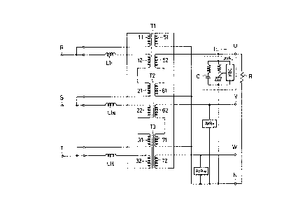
Fig. 1 is a circuit diagram illustrating in schematic
form the construction of one working example of this
invention.
The three-phase transformers Tl, T2, and T3 are sever-
ally provided with mutually equivalent paired primary (input)
windings 11 and 12, 21 and 22, and 31 and 32. The trans-
formers Tl, T2, and T3 are likewise provided with mutually
equivalent paired secondary (output) windings 51 and 52, 61
and 62, and 71 and 72.
Of the paired primary windings of these transformers,
the second windings 12, 22, and 32 are connected, each at one
end thereof, to the three-phase input terminals R, S, and T
through the medium of series reactors Llr, Lls, and Llt and
connected, each at the other end thereof, to one end of the
first windings 21, 31, and 11 of the adjacent phases, respectively.
The remaining ends of the first windings 11, 21, and 31 are
directly connected to the corresponding three-phase input
terminals R, S, and T.
In other words, on the primary sides of the trans-
formers, the series reactor and the second winding of one of
the phases and the first winding of the phase adjacent
thereto which are in series connection are treated as one
phase winding and, as such, are joined in delta connection.
~303694
_ 11 -
On the secondary sides oF the transformers, of the
paired windings, the second windings 52, 62, and 72 are
directly connected, each at one end thereof, to the three-
phase output terminals U, V, and W and connected, each at the
other end, to one end of the first windings 61, 71, and
51 of the transformer of the adjacent phase, respectively.
The remaining ends of the first windings 51, 61, and 71 are
directly connected to a neutral point N.
Further on the secondary sides, similarly to the
primary sides mentioned above, the second winding of one of
the phases and the first winding of the phase adjacent
thereto which are in series connection are treated as one
phase winding and, as such, are joined in Y connection.
Constant voltage regulating means AVRU, AVRv, and AVRw
are inserted respectively between the neutral point N and
the output terminals U, V, and W. These constant voltage
regulating means may be arranged similarly to the conven-
tional types illustrated in Fig. 10 or may be suitably
arranged otherwise.
In Fig. l, the AVR circuits are illustrated as having a
reactor connected in series with an output capacitor C.
Optionally, this reactor may be omitted.
Now, the circuit of Fig. l will be considered below with
respect to a configuration having a load R connected between
the output terminal U and the neutral point N and having the
other output terminals left open or kept under no load.
~ '~
,,
:;
' `
1303694
The load current Iu ln the U phase flows to the
secondary windings 52 and 61 of the transformers Tl and T2
and, as the result, the primary current flows through the
series reactor Llr and the primary windings 12 and 21. The
voltage drop produced between the opposite terminals of the
series reactor Llr by the primary current gives rise to a
phase delay of 2~ in the output voltage Vun of the U phase.
Since the primary windings 12 and 21 are substantially
equivalent, a phase delay of roughly ~ occurs in each of
these windings.
As clearly noted from Fig. 1, the current with a phase
delay of ~ flows in the series reactor Lls and the primary
winding 22 because the primary winding 21 is coupled also
to the primary winding 22 and the secondary winding 62. As
the result, the phase of the output voltage Vvn of the V
phase is delayed similarly by ~.
In the same manner, the current with a phase delay of 0
flows also in the series reactor Llt and the primary winding
32 because the primary winding 11 is serially connected to
the primary winding 32. As the result, the phase of the
output voltage Vwn of the W phase is also delayed by ~.
As surmised from the explanation given above, the
voltage phases on the input and output sides are related as
indicated by the vector diagram of Fig. 2. Fig. 2 depicts
the output voltage Vun of the U phase as having a phase delay
of 2~ relative to the input voltage Vrs of the R phase, the
.
.
.
~303694
- 13 -
output voltage Vvn oE the V phase as having a phase delay of
relative to the input voltage Vst of the S phase, and the
output voltage Vwn of the W phase as having a phase delay of
~ relative to the input voltage Vtr of the T phase.
It follows that the phase difference between output
phases is tl20 - ~) between U and V, 120 between V and W,
and (120 + ~) between W and U. Thus, the deviation in the
phase difference between the output phases is +0, repre-
senting an improvement of roughly 1/2 over the conventional
prior art.
The preceding embodiment has been assuemd as using a
plurality of windings on the transformers which are equiva-
lent and balanced mutually. It will be readily inferred that
substantially the same effect is obtained even when these
windings are not perfectly balanced.
In the case of the windings which are out of balance,
the phase delay in the U phase is (Ov + Ow) when the phase
delay in the V phase is ~v and the phase delay in the W phase
is ~w. It follows that the phase difference between output
phases is (120 - ~w) between U and V, (120 + ~w - ~v)
between V and W, and (120 + ~v) between W and U.
The embodiment under discussion, owing to the special
devices employed in the construction and connection of the
transformers Tl to T3, brings about an effect of decreasing
the deviation in phase difference between the output phases
during the operation of an unbalanced load to about one half
.,
.
.
-` 1303694
- 14 _
of the deviation involved in the conventional prior art
without requiring any reduction in the reactance of series
reactor.
Evidently, the circuit of Fig. 1 can be realized by
using diport transformers which are provided with magnetic
shunts. One example of this configuration is illustrated in
Fig. 3. In this diagram, the same symbols as used in Fig. 1
denote identical or equivalent parts.
TSl to TS3 stand for diport transformers provided
respectively with magnetic shunts. These diport transformers
contribute to simplifying the configuration by obviating the
necessity for using series reactors as external circuit
elements. Since they have entirely the same operation as
those of Fig. 1, the explanation thereof will be omitted.
The circuit having the configuration of Fig. 1 can be
applied to a two-way uninterruptible AC power supply using an
inverter output as well as the conventional commercial
AC power supply as inputs. One example of the application
is illustrated in Fig. 4. In the diagram, the same symbols
as used in Fig. 1 denote identical or equivalent parts.
As clearly noted from Fig. 4 as compared with Fig. 1,
the present embodiment represents a configuration involving
addition of windings lla, 12a, 21a, 22a, 31a and 32a and
series reactors L5r to L5t for the second input power
supplies (R2, S2, and T2) on the primary sides of the trans-
formers Tl to T3.
~303694
- 15 _
Since the operation of this embodiment is easily
inferred from the operation of the conventional two-way
uninterruptible AC power supply as shown in the U. S. Patent
No. 4,556,802 specification and from the description given
abo~e, the explanation of the operation will be omitted.
Fig. 5 depicts an embodiment realizing the circuit of
Fig. 4 with three triport transformers. In this diagram, the
same symbols as used in Fig. 3 and Fig. 4 denote identical
or equivalent parts. MSll, MS12, MS21, MS22, MS31 and MS32
denote magnetic shunts for the triport transformers TS1 to TS3.
The fact that the embodiment of Fig. 5 has the same
operation as that of Fig. 4 is easily inferred from the
operation of the conventional two-way uninterruptible AC
power supply and from what has been described so far.
In the embodiments described above, the ferroresonant
three-phase constant AC voltage transformer contemplated by
this invention is invariably configurated by using
independent transformers one each for the three phases and
forming a plurality of windings on each of the transformers.
As noted from what has been described so far, it is
desirable for the sake of this invention that the electric
properties ~magnitude of resistance, magnitude of
inductance, and number of turns) of the paired windings (such
as, for example, the windings 11 and 12, lla and 12a, 12 and
21, and 52 and 61) should be mutually equal.
For this purpose, the adoption of the bifilar
~ 303694
- 16 -
winding may be conceived for the windings to be ~ormed on one
and the same transformer. In the case of windings to be
formed on different transformers, since no proper measure is
available, it is difficult to form paired windings possessing
practically the same electric properties.
Further since the number of windings is multiplied, the
configuration entails a disadvantage that it is large and
heavy, consumes much time and labor in manufacture and
assembly, and becomes expensive.
Fig. 6 is a perspective view illustrating in schematic
form another embodiment of this invention which is suitable
for the elimination of the drawbacks of the nature described
above. The embodiment of Fig. 6 corresponds to that of Fig.
5. In other words, the equivalent circuit of the configur-
ation of Fig. 6 is as shown in Fig. 5.
This embodiment makes use of the following basic
operating principle. As illustrated in Fig. 7, the adjacent
legs, one each, of a pair of rectangular frame-shaped iron
cores TCl and TC2 are juxtaposed and a common winding 3 is
formed on the juxtaposed legs and separate windings 6 and 9
are formed respectively on the remaining legs of the iron
cores TCl and TC2. The transformer thus configurated has an
equivalent circuit as illustrated in Fig. 8. As apparent
from Figs. 7 and 8, applying a common winding on a part of
each magnetic path of the two transformers is equivalent to
; forming independent windings on the magnetic paths and
1303694
- 17 -
connecting the separate windings in series.
In the configuration of Fig. 6, three transformers TSl
to TS3 are each formed of a rectangular frame-shaped iron
core and a pair of magnetic shunts MS11 and MS12, MS 21 and
MS22l or MS31 and M~32 (which are partly hidden in the
diagram) to form three winding sections (windows).
These transformers are put up approximately in the shape
of three faces of a triangular prism so that the adjacent leg
parts of two of the three transformers will stand side by
side as illustrated, with common windings formed one each on
three pairs of leg parts. Since the iron cores are divided
into three winding sections as described above, the windings
are applied one each to these winding sections.
In the illustrated configuration, one set of output
windings 91, 92, and 93 is formed in the second winding
section at the center and two sets of input windings 41 to 43
and 81 to 83 are formed respectively in the first and third
winding sections in the upper and lower parts.
The output winding 91 in the configuration of Fig. 6
corresponds to the output windings 52 and 61 in the configur-
ation of Fig. 5. The other windings in the configuration of
Fig. 6 evidently correspond each to two windings in pair in
the configuration of Fig. 5. Thus, it is easily inferred
that the configuration of Fig. 6 corresponds tothe trans-
formers of Fig. 5.
It is also self-evident that the circuit illustrated in
~303694
- 18 -
Fig. 4 is realized by the configuration in Fig. ~5 which
is equal to the configuration involving removing all of
the magnetic shunts from the iron cores TSl to TS3 and
connecting series reactors to the input windings 41 - 43
and 81 - 83 in Fig. 6.
It is further evident that the embodiments of Fig. 1
and Fig. 3 are realized by the configurations shown in
Figs. 13 and 14, respectively. These embodiments are
realized by combining three iron cores similarly to the
embodiment of Fig. 6 and applying common input and output
windings one each to paired leg parts of the adjacent
transformers, namely by removing one set of input windings
and magnetic shunts from the configuration of Figs. 15 and
6.
The embodiments described above have been assumed as
using an automatic voltage regulating means of the type
provided with a feedback circuit. As easily inferred from
what has been described above, the automatic voltage
regulating means may be in some other suitable type. In
the embodiments described above, the windings on the
primary side have been assumed as being the delta
connection pattern and those on the secondary side the Y
connection pattern. Of course, any one of the two
connection patterns mentioned above can be optionally
adopted for the primary and secondary side wirings.
: '
" ~ ~
~'`''' ~ , .
, : '
--`` 1303694
- 19 -
Effect of the Invention:
As is evident from the description given above,
the present invention brings about the following effects:
(1) The deviation produced in phase difference among the
output side phases when the three-phase load goes out of
balance can be decreased.
(2) The power capacity on the input side can be minimized
because the cùrrent-limiting effect is maintained by
maximizing the magnitude of reactance of the series
reactors inserted on the input side.
(3) The effects of (1) and (2) shown above can be
realized by applying common windings one each to the leg
parts of a pair of transformers of the adjacent phases
without increasing the number of windings as compared with
the conventional countertype.
:'
' ~
': ~
'''
~ ::
~, ,, .~....
~2: ~
~ ,
,,~
.