Note : Les descriptions sont présentées dans la langue officielle dans laquelle elles ont été soumises.
13~3~..8
-- 2
1 BACKGROUND OF THE INVENTION
This invention relates to an apparatus for
erecting and lining up elongated bottles, cans, moulded
parts, or the like, of various shapes and sizes, into a
standing position with the filler-opening at the top for
subseguent transfer to a transporting device. More
particularly, the invention relates to such an apparatus
which comprises a circular rotating disc, a shaft which is
at an angle to the vertical, an upwardly open housing
being provided around the said rotating disc, the said
housing being cylindrical or funnel-shaped below the
rotating disc, individual downwardly extending chutes
being arranged in the edge area of the rotating disc and
places for the moulded parts to lie, provided with baffle-
plates, being arranged above the said chutes, the said
*
3~. 8
-- 3
1 places for the moulded parts to lie being openings
machined into the outer edge of the rotating disc and
running tangentially thereto, and the said places being
closed off from the said chutes by a stationary bottom
arranged in the vicinity of the passages in the housing,
the said bottom being briefly interrupted, in the vicinity
of the uppermost point of the peripheral track in the edge
of the rotating disc, to allow the moulded parts to fall
through.
An apparatus having similar characteristics is
known (German Patent 2 651 495) in which the openings in
the edge of the rotating disc, serving as places for the
moulded parts to lie, are adapted approximately to the
length of the said moulded parts. The moulded part must
be arranged in its place in such a manner that the opening
through which it is filled, namely the neck in the case of
a bottle, is directed upwardly when it reaches the
chute. In the case of laterally open beakers or cans,
suitable moulded parts must be fitted to the edge of the
opening. Moreover, additional tilting parts are fitted in
the chute in order to guide the moulded part into the
correct position therein. The main disadvantage of this
design of places for the moulded parts to lie is that,
because of the variety of moulded parts to be processed,
the annular segments containing these places, and located
13~3~.8
~, ~
^ 4 --
1 at the periphery of the rotating disc, must be changed.
Not only do such changes take time and money, but a large
stock of annular segments is needed. Another substantial
disadvantage is that the closely adapted openings to the
places make occupancy of the rotating disc difficult,
since a moulded part is not transported through each place
by the disc which rotates as rapidly as possible.
Misshapen moulded parts, or those which fall badly, may
become caught as they pass through the narrow opening,
leading to stoppages. Close occupancy of the chutes
requires high r.p.m. which again has a detrimental effect
upon the transfer of bottles from the chutes to the
conveyor-belt.
SUMMARY OF THE INVENTION
It is the purpose of the invention to design an
apparatus of the type mentioned at the beginning hereof in
such a manner that the opening may be made so large that a
variety of parts can be processed without changing the
annular segments, thus eliminating the need for separate
baffle-plates.
The purpose of the invention is accomplished in
that pivotable or sliding bottoms or supporting surfaces
are provided as baffle-plates in the vicinity of the
openings, the positions of the said bottoms being adapted
`" 13~43~.8
- 5 -
1 to be controlled, as a function of the positions of the
moulded parts, by means of an optical or electronic
device.
According to one advantageous configuration,
mounted on the side of the chute facing the shaft of the
rotating disc is a lever acting as a baffle-plate and
projecting into the opening, the said baffle-plate being
pivotable, in the one terminal position, by means of a
stationary stop-roller and, in the other terminal
position, by means of a controllable stop-roller, the said
controllable stop-roller beinq arranged, as seen in the
direction of travel, in the vicinity of the optical or
electronic device. It is also advantageous for the lever
to be mounted upon the rear wall of the chute and for a
pin to be fitted to the projecting pivot-axis, the said
pin running at right angles thereto and coming to rest
against stops for the purpose of limiting the pivoting
movement.
It is also advantageous for bottoms divided in
the middle of the openings, or retractable bottoms, or
bolts, to be provided as baffle-plates.
Finally, it is advantageous for pneumatic or
electro-mechanical drives, or mechanical switching points,
to be provided to control the movement of the bottoms or
bolts.
3~318
- 6 -
1 The important advantage provided by the
invention is that a specific number of different
magnitudes can be processed with a given magnitude of
opening and therefore of the place in which the moulded
part lies, with no need to change the segments. Another
advantage is that the places arranged in the edge of the
rotating disc can achieve optimal occupancy, allowing the
rotating disc to be driven at a favourable speed. In
addition to this, the moulded parts are handled
particularly gently.
In one aspect of the invention there is provided
an apparatus for erecting and lining up elongated bottles,
cans, moulded parts, or the like, of various shapes and
sizes, into a standing position with the filler-opening at
the top, with subseguent transfer to a transporting
device, and comprising:
a circular rotating disc,
a shaft of said rotating disc which is at an
angle to the vertical,
an upwardly open housing being provided around
the said rotating disc, the said housing being cylindrical
or funnel-shaped below the rotating disc,
individual downwardly extending chutes being
arranged in an edge area of the rotating disc,
-7 _ 13~3~8
1 places ~oc the moulded parts to lie being
arranged above the said chutes, said places being provided
with baffle-plates, said places being openings machined
into an outer edge of the rotating disc and running
tangentially thereto, and ~he said places being closed off
from the said chutes by a stationary bottom arranged in
the vicinity of the passages in the housing,
the said bottom being briefly interrupted, in the
vicinity of an uppermost point of a peripheral track in
the edge of the rotating disc, to allow the moulded parts
to fall through,
characterized in that the baffle-plates, arranged
in the vicinity of the openings, are in the form of
pivotable or sliding bottoms or supporting surfaces, the
positions of which are adapted ~o be controlled, as a
function of the position of the moulded parts, by means of
an optical or electronic device.
in another of its asp~cts, the invention
provides an apparatuQ for orienting rando~ly oriented oblong
bottles and like-shaped objects into upright orientation
with a filling end pointing upwardly and followed by
delivering the bottles one by one to a horizontal transfer
device, and including a housing adapted to receive randomly
oriented bottles and having an inclined shaft concentrically
and rotatably arranged in the housing; a turntable means
concentrically fixed to said shaft, said houqing enclosing
said turntable and having a funnel-shaped lower region; a
plurality of 3paced openings at the periphery of said
13~43~.8
- 7a -
turntable means, each opening adapted to receive one of said
bottles; a plurality of individual fall shafts aligned with
and vertically spaced from said openings, said fall shafts
being attached to ~aid turntable mean3 and converging
downwardly to a funnel ~hape to conform with said funnel-
shaped lower region of the housing; a fixed floor arranged
between ~aid openings and said fall ~hafts to prevent the
bottles from falling through aid openings and into the fall
qhafts, said fixed floor further having a gap in the
vicinity of the upper most point of the revolution path of
the ~urntable to permit the bottles to fall into said fall
shaft~; the improvement comprising a baffle plate pivotally
attached to each fall shaft, said baffle plate comprising a
swingable lever and control means for po~itioning the lever,
depending upon the position of the bottle, to contact the
bottle adjacent the filling end, the lever acting a~ a
fulcrum to permit the end opposite the filling end to fall
first through said shaft.
BRIEF DESCRIPTION OF THE DRAWINGS
-
The invention is explained hereinafter in
greater detail in coniunction with the example of an
embodiment illustrated in the drawings attached hereto,
wherein:
~'
~3~J4318
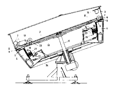
1 Fig. 1 is a diagrammatical view of one
embodiment of an apparatus of this kind;
Fig. 2 is a longitudinal section through the
embodiment of Fig. 1.
S Fig. 3 is a plan view of the apparatus;
Fig. 4 is a part-section through the apparatus
with the stationary stop-roller;
Fig. 5 is a part-section through the apparatus
with the controllable stop-roller;
Fig. 6 is a part-section through the rotating
disc with the chute arranged thereunder in the uppermost
position of the peripheral track;
Fig. 7 is a ground-plan of Fig. 6;
Figs. 8 and 9 correspond to Figs. 6 and 7 but
with the moulded part reversed;
Fig. 10 is a side view of a segment with a
chute, in cross-section;
Fig. 11 is a partial front view of the segment;
Fig. 12 is a plan view of such a segment;
Fig. 13 is a block wiring diagram for the
electronic control-device at a first identification point,
and
Fig. 14 shows the control-device at a second
identification point.
~3(~3113
g
1 DESCRIPTION OF THE PREFERRED EMBODIMENT
. ~
The overall layout of the apparatus may be
gathered from Figs. 1 to 3. It comprises, in particular,
a circular disc 2 rotating at an obli~ue angle mounted on
a shaft at an angle to the vertical. Fitted to the
periphery of the said disc are individual annular segments
17 having rectangular openings 8 at their outer edges
which serve as places for the moulded parts to be
transported to lie. The length of these openings 8 is
tangential to rotating disc ~. Located below the latter
is a circular support 16 which rotates with the disc and
has an annular area 22 projecting therefrom upon which
annular segments 17 are supported in part. Chutes 4 are
fitted to annular segments 17, each in the vicinity of an
opening 8. The said chutes are U-shaped in cross-section
and comprise two lateral walls 23 and a rear wall 12
directed towards shaft 11. These chutes taper downwardly,
as may be gathered from Figs. 3, 6, 8 and 11, for
example. Rotating disc 2, together with annular segments
17, is arranged within a housing 3 which is of cylindrical
design above disc 2 and is funnel-shaped below disc 2.
Located in the edge area of annular segments 17, below
openings 8, is a stationary bottom 9 which is fitted to
housing 3, extending approximately to uppermost point 10
of the peripheral track, and comprising there an
~3~
-- 10 --
1 interruption 18 for the passage of the moulded parts
(Figs. 6 to 9 and 14). Arranged vertically in the
vicinity of uppermost point 10 of the peripheral track are
chutes 4, and moulded parts 7 are transferred in this
vertical position to a transporting device 1. Housing 3
is provided with a bottom 24 which simultaneously defines
chutes 4.
Individual moulded parts 7, arranged in their
places 6, are transported from the lowermost point in the
apparatus to uppermost point 10 on the peripheral track.
In this connection, care must be taken to ensure that the
moulded parts reach the chutes with their filler-openings
uppermost. To this end, a separate baffle-plate 5 is
associated with each chute. In the example of embodiment
illustrated in the drawings, the said baffle-plate is in
the form of a U-shaped lever comprising an elongated arm
25 running downwardly towards the chute and a finger 26
extending at right angles just beneath opening 8. The
design of baffle-plate 5 may be gathered more particularly
from Figs. 4 to 9. Located at the lower end of elongated
arm 25 is a pivot-axis 19 mounted upon rear wall 12 of
chute 4. The mounting is located in the lower part of the
chute and approximately centrally (Figs. 6 and 8).
Located at the end of pivot-axis 19 is a pin 20 running at
right angles to the axial direction. The two terminal
~3~3~
1 positions of lever 5 are defined by stops 21 which are in
the form of pins fitted to rear wall 12. In order to
adapt to moulded parts 7 of different sizes in places 6,
the pivot angle of baffle-plate 5, and thus the terminal
position of finger 26, is adjustable, for example, by
inserting pin 21 in other positions in rear wall 21. The
terminal positions of lever 5, either in the direction of
travel of rotating disc 2, or opposite to it, are selected
in response to the position of the moulded part 7. If,
for example, the opening in moulded part 7 is in the
direction of travel 27, then lever 5 is pivoted to the
front, so that the opening in the moulded part may be
supported by finger 26. On the other hand, if the opening
is arranged in a direction opposite to the direction of
lS travel (Figs. 8 and 9), then lever 5 is pivoted in the
opposite direction, so that, here again, the opening in
the moulded part is supported by finger 26 and the moulded
part can reach chute 4 accordingly. Control of the
movement is effected by a stationary stop-roller 13 and a
controllable stop-roller 14. Stationary roller 13 is
located on the peripheral track after the point at which
ejection of moulded parts 7 takes place in Fig. 4
approximately in the vicinity of the lowermost point in
the peripheral track behind rear wall 12 of chute 4, and
it is secured in a mounting 28, for example, on bottom 24
~3~`~3~B
- 12 -
1 of housing 3. ~evers 5 are basically aligned in one
direction at this stationary stop-roller 13. An optical
or electronic device 15, for identifying the position of
moulded parts 7, is located in the vicinity of the
peripheral track, in the direction of uppermost point 10
of the curve, i.e., in a position in which the said
moulded parts are separated. In this position, or as seen
in the direction of travel 27, but thereafter before
interruption 18 in bottom 9, is located controllable stop-
roller 14 (Fig. 5) which is also fitted to a mounting
28. Said controllable stop-roller 14 is connected to a
pneumatic cylinder 29 which is controlled as a function of
the position of moulded part 7 in its place 6 and of the
position of lever 5.
Figs. 10 to 12 show the design of annular
segments 17. Chutes 4 are fitted to these segments
according to openings 8, as are insert-shoes 30 by means
of which annular segment 17 is pushed over edge area 22 of
circular support 16. Annular segments 17 are placed upon
circular support 16 and are screwed between adjacent
segments by means of connecting tabs 31.
Figs. 13 and 14 illustrate the control-device
which actuates stop-roller 14. The control-device
comprises a trigger-unit 32 which, as the synchronizing
element, is responsible for the r.p.m. of the disc, the
~U43~L8
- 13 -
1 position of the bottles in the disc, a light-source
control, and for the positional and velocity control of
the mechanics and timing of the comparison process of the
control-electronics. Subse~uent control-logic 33
evaluates the information obtained by comparison unit 34
and optical indentification system 35, compares it with
the ideal, and passes corresponding signals to a control-
unit 36 which then actuates pneumatic cylinder 29 of
controllable stop-roller 14. Associated with the optical
identification system is a triggered light-source 37.
Optical or electronic device 15 (Fig. 2) makes
it possible to identify the exact position of the moulded
part in its place 6 and to control stop-roller 14
accordingly. The optical identification system may be in
the form of a photoelectric cell or of a single- or multi-
line camera (CCD), for example. For the purpose of
identifying the positions of the receptacles and moulded
parts 7, use may also be made of another electronic
device, e.g., an initiator, and ultra-sound device, or a
laser device.
In the example of embodiment illustrated in the
drawings, baffle-plate 5 is in the form of a separate
lever. A bottom divided in the middle of opening 8 may
also be provided in place of such a lever. Furthermore, a
retractable bottom or bolt may be used as the baffle-
plate.
13~43~8
- 14 -
1 In overview, the apparatus serves to erect and
line up elongated moulded parts 7 into a standing position
with the filler-opening at the top, with subsequent
transfer to a transporting device. It consists of a
circular rotating disc 2, shaft 11 of which is at an angle
to the vertical, a cylindrical housing 3, open upwardly,
being arranged around the said rotating disc below which
the said housing is cylindrical. Arranged around rotating
disc 2 are annular segments 17 having individual chutes 4
extending downwardly, places for moulded parts 7 to lie
being provided, above the said chutes. The places for the
moulded parts to lie are openings machined into the outer
edges of annualar segments 17, running tangentially to the
edge, and are closed off by a stationary bottom 9
arranged, in the vicinity of openings 8, upon housing 3,
the said bottom being briefly interrupted, in the vicinity
of uppermost point 10 of the peripheral track in the edge
of annular segments 17, to allow the moulded parts to fall
through. Baffle-plates 5 provided in each chute 4 are in
the form of pivotable supporting surfacesr the position of
which is adapted to be controlled, as a function of the
position of moulded part 7, by means of an optical or
electronic device 15.
While the invention has been described in
reference to preferred embodiments, it is not so
~ 15 -
1 limited. Many modifications and variations will occur to
a person skilled in the art. For a definition of the
invention, reference is made to the appended claims.