Note : Les descriptions sont présentées dans la langue officielle dans laquelle elles ont été soumises.
i30473S
A MODULAR DRILLING TEMPLATE FOR DRILLING SUBSEA WELLS
sackground and Summary of the Invention
The present invention relates to a template for facilitating
the drilling of subsea oil and gas wells. More particularly, the
present invention relates to a light-weight, cost-effective, modular
S design for such a template that can more easily be installed and
leveled.
The drilling template of the present invention was speci-
fically designed for utilization in commercializing a field in the
Gulf of Mexico off the Louisiana coast in approximately 1800 feet
(550m) of water. Soundings of the ocean floor targeted for template
placement indicated a silty, unstable mud bottom that was incapable of
supporting a conventional drilling template. This suggested a light
weight configuration might be in order. On the otherhand, placement
in water depths of 1800 feet, necessitates a design with sufficient
strength to avoid collapsing under the hydraulic pressure exerted by
the ocean. Therefore, weight reduction could not be made without
regard to strength requirements.
The template design of the present invention affords both a
light-weight solution and a configuration having sufficient strength
to survive the rigors of the environment at a 1800 foot water depth.
A frame is constructed of tubular steel members that are reinforced
with ring stiffeners. The frame defines a number of (in the specific
embodiment shown, six) pod-receiving openings. Well pods, that may be
installed as necessary to enable the drilling to proceed, are secured
into the individual openings and, preferably, provide cylindrical
guides for drilling a plurality of (in the specific embodiment de-
picted, four) wells.
The light-weight template frame is equipped with a plurality
of buoyancy tanks (at least some of which are floodable and one,
removable) to enable the template to float at the field site so that
it may be rigged for placement on the ocean floor. The floodable
~k
13Q4`7~S
-- 2 --
tanks may then be ballasted to the weight desired by controling valved
flood ports, for floor installation. Cathodic protection is provided
in the form of sacrificial anodes mounted at spaced locations along
the tubular frame. The pile sleeves of the frame are provided with
conventional slips to grip the pin piles that are used to secure the
template to the seafloor. By engaging the template near its lowest
corner and lifting, a rough level for the template (which is roughly
50 feet by 80 feet by 20 feet at its tallest end) can be obtained.
The individual well pods can be inserted in the openings and
are secured in place by engagement of a plurality of latch mechanisms
in a like plurality of latch-engaging receptacles. A fine tune
adjustment of the level of the individual pods can be made by adjust-
ment of gimbaled jack mechanisms associated with each of the latches.
The modular template has several advantages over conven-
tional one piece designs. The weight reduction to facilitate leveling
has already been mentioned. Another is cost avoidance or, at least,
cost postponement, since subsequent well pods need only be added as
successful drilling indicates installation to be warranted. Yet,
another is that a pod that is damaged may be retrieved and repaired or
replaced before drilling commences. In a conventional template
design, no such flexibility is afforded and a damaged cylindrical
guide for the drill string generally precludes the intended well from
being drilled or requires significant effort to repair or replace it
on the ocean floor.
Yet another feature of the present invention involves the
placement of the drilling and foundation templates. The drilling
template may be lowered and secured in place with piles, the docking
pile guide frames attached in position, and the docking piles in-
stalled. When production becomes imminent, the foundation template
set around the drilling template and the production platform secured
thereto. This also allows the cost associated with the placement of
the foundation template to be avoided, or at least delayed, until the
i3Q4'735
-- 3 --
delineation drilling has shown the field under development to have
significant commercial potential.
Various other features, advantages and characteristics of
the present invention will become apparent after a reading of the
following description.
Brief Description of the Drawings
Fig. l is an exploded elevational view of the modular
template of the present invention showing the template frame as it
would be configured for floating on the surface and indicating how a
pod would be received in an opening;
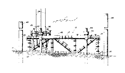
Fig. 2 is a side view of the modular template frame with
parts broken away, said frame piled and leveled on the seafloor with
the docking piles installed and the first pod inserted and secured in
its opening;
Fig. 3 is a detailed side view in partial section of one of
the guide rods with the pod positioned in the template frame;
Fig. 4 is a detailed side view in partial section of an
exemplary slip mechanism that may be used for rough leveling the
template;
Fig. 5 is a detailed side view in partial section of the
J-latch receptacle engaged by a running tool to facilitate rough
leveling;
Fig. 6 is a detailed side view with portions cut away
showing the latch mechanism and its associated leveling jack; and
Fig. 7 is a schematic top view showing how the foundation
template is positioned around the drilling template.
Detailed Description of the Preferred Embodiment(s)
The drilling template of the present invention is shown in
Fig. 1 generally at 10. Template 10 is comprised of two main
components: a light-weight tubular frame 12 and a plurality of (one
shown) well pods 14. Frame 12 is constructed of tubular members 16
that have ring stiffeners 18 formed thereon to stiffen (or reinforce)
~04t735
tubular members 16. Ring stiffeners 18 provide the walls of tubular
members 16 with sufficient strength, in conjunction with the wall
thickness, to prevent the walls from collapsing under the hydraulic
pressure from the 1800 foot water depth. Sacrificial anodes 20 are
affixed periodically along the lengths of members 16 to inhibit
cathodic reaction on the subsea template 10. Tubular frame members 16
define a plurality of pod-receiving openings 22 (six being shown).
Template frame 12 will be mounted on a pair of wooden skids
13 to facilitate its removal from a launching barge, or the like.
Positioned around the periphery of each pod receiving opening 22 are a
plurality of receptacles 24 that may selectively receive guide rods
26. As shown in Fig. 3, each guide rod 26 has a frusto-conical seat
28 that is received in conically shaped funnel 30 of receptacle 24.
One or more retractable dog(s) 32 protrudes below the bottom of
receptacle 24 and latches guides rod 26 in place. A guide wire 34
extends from each guide rod 26 to the surface for the purpose of
guiding well pod 14 into proper position in its respective opening 22.
Guide wires 34 and guide rods 26 will also be used to properly locate
other items such as pin piles and docking piles, as well.
Also located about the periphery near the corners of each
opening 22 are a plurality of latch-engaging tubes 38 which are also
each equipped with conical guide funnels 39 to facilitate entry of
latch mechanisms 40 of well pods 14. A plurality of pile sleeves 42
(four shown) are provided for receiving pin piles 44 (Fig. 2) to affix
template 10 in a particular location on the seafloor 11. Buoyancy
tanks 46 extend between pairs of sleeves 42 and a removable tank 48 is
mounted adjacent one end of template frame 12. Buoyancy provided by
tanks 46 and 48, as well as by tubular frame members 16 themselves,
enable the template to float at the drillsite so that it may be rigged
with a sling to lower it to the seafloor using a drill string, or the
like. Tank 48 is removed and tanks 46 and the remainder of frame
members 16 are ballasted to provide the desired lowering weight by
1304~73~
-- 5 --
opening valved ports (not shown) located on the various structural
members.
Once template 12 is seated on the seafloor 11, pin piles 44
are inserted into the ocean floor through sleeves 42 using any one of
a number of conventional pile driving or drilling techniques. The
technique preferred for this application involves the use of a tubular
pile through which a drill string can be inserted. As the hole is
drilled through the pile, the weight of the pile causes it to sink
into the muddy bottom. By way of example, pin piles 44 that are 280
feet in length will be drilled 250 feet or so into the ground tsome
25-30 feet protruding from the seafloor 11).
As shown in Fig. 2, the seafloor 11 designated for template
installation has an incline of approximately 6. The templa.e frame
12 is constructed with a complementary taper to make the upper tem-
plate surface generally level. Each pile sleeve 42 is equipped with a
slip assembly 50 (Fig. 4) to facilitate a coarse leveling of the
template (within 1) should one corner sink more deeply into the soil
or, if for any other reason, the template prove to be out of level.
These slip assemblies 50 may be uni-directional (i.e., resist only
downward motion) through mechanical devices such as camming surfaces
52 and springs 54 that bias arcuate slips 56 into engagement with the
surface of pile 44. Alternatively, the slips may be actuated to
engage piles 44 by hydraulic, pneumatic or electronic (e.g., solenoid)
means, as shown in U.S. patent 4,212,562, for example.
The template frame 12 is equipped with a receptacle 58
adjacent each pile sleeve 42. Receptacles 58 each have a J-latch slot
60 engagable by a running tool 62. Should the template frame 12 not
be leveled within design tolerance (1, as mentioned earlier), running
tool 62 will be engaged in J-latch slot 60 of the lowermost sleeve 42
and raised, as needed. Both the initial level and the effect of the
adjustment will be detected by a video camera mounted within a remotely
operated vehicle used to view the leveling bubbles (not shown)
- 13U~7~S
positioned on lateral and longitudinal frame members 12. The adjust-
ment of the template pile sleeves will continue as necessary until the
degree of level desired is provided.
Pod 14 comprises a generally rectangular frame formed by
lateral members 64 and longitudinal members 66. Actually, lateral
members 64 and longitudinal members 66 define a square that can be
received inside pod-receiving openings 22. End extensions 68 of
longitudinal members 66 protrude outwardly from the square such that
latch mechanisms 40 overlie the centerlines of frame members 16 so
that they may be secured in latch-engaging tubes 38. Pod guide
sleeves 70 are similarly mounted on arms 72 to overlie and engage
guide rods 26. This length difference requires that pods 14 be
installed in template openings parquet-style, alternately extending
laterally and longitudinally in adjacent pod-receiving openings 22.
By examining the differences in the positions of the guide rods 26
between Fig. 1 and Fig. 2 (Fig. 1 depicting a pod in the back corner,
Fig. 2 the front corner), one can appreciate the consequences of this
parqueting. The specific parquet patern is shown schematically in
Fig. 7.
Pod 14 supports one or more cylindrical sleeves 74 for
guiding a drill string (not shown) during well drilling operations.
The specific configuration depicted in the preferred embodiment shows
pod 14 configured with four such sleeves 74. A plurality of guide rod
receptacles 76 (eight shown) are positioned about the upper periphery
of pod 14. Once pod 14 is secured in place, guide rods 26 will be
retrieved by retracting dogs 32 and reeling in guide wires 34. The
inside diameter of sleeve 74 is sufficient to permit unobstructed
passage of frusto-conical seat 28. The same guide rods 26, or others,
may then be received in receptacles 76 to permit other equipment, such
as the drill string, to be lowered into position.
The details of latch and leveling mechanism 40 are shown in
Fig. 6. An extendable leg 78 is telescopically received within leg 80
that is attached to pod 14. Extendable leg 78 is mounted on screw
jack 82 by a gimbal nut 84. A pair of pivot pins 86 (one shown) are
threaded into each side of gimbal nut 84 and rotationally support
pivot frame 87 to which leg 78 is attached. By engaging and rotating
hex head 88 on screw jack 82, leg 78 may be extended to provide the
desired level of pod 14 and hence the verticality of cylindrical
sleeves 74. This adjustment can be done at the surface before the pod
is lowered or after the pod 14 is installed in its opening 22 by a
remotely operated vehicle. The gimbaled nut 84 enables one leg 78 to
be extended with respect to the other three without binding in the
tubes 38. It will be appreciated that it is extremely important that
sleeves 74 be vertical to help insure that the initial engagement of
the drill string is not angular so that the wellbore, wellhead, and
associated equipment will be vertically positioned. Leveling bubbles
(not shown) on well pod 14 facilitate the fine tune leveling process.
Latching dogs 90 are slidably mounted by virtue of pins 92
received in slots 93 are secured to the lower end 94 of extendable leg
78. Springs (not shown) bias latching dogs 90 to their outward (or
latching) position. Thus extended, dogs 90 will engage under inwardly
protruding flange 37 formed within tubes 38 thereby preventing inad-
vertent removal of pod 14 from frame 12.
Detachable docking pile guide 95, one of which will be
received on each end of template frame 12, is shown in Fig. 1 (one
shown). Guide 95 comprises a frame 96 mounting a cylinder 97 that
receives docking piles 45. Frame 96 includes a pair of cylindrical
pins 98 that are received in sleeves 35, sleeves 35 forming part of
frame 12. A similar pair of pins (not shown) are formed as extension
of legs 99 that are received in tubular sleeves 36 that also form part
of frame 12. Docking pile guide frames 95 may be attached to template
frame 12 prior to lowering but, more preferably are run into place
using guide wires connected to guide rods 26 after the template frame
has been deposited and leveled on the seafloor 11. Docking piles 45
~3U~'735
will be installed in a manner similar to pin piles 44 and need not be
quite as long (piles 45 may, for example, be on the order of 200 feet
long and drilled to a depth of 160 feet so that some 40 feet extends
above the seafloor 11). Once piles 45 are in place, dock pile guides
9S may be retrieved as, for example, by retrieving guide rods 26. The
aperture in the corresponding sleeve of the frame 95 will be insuffi-
cient to provide the clearance depicted in Fig. 3 and frame 95 will
travel upwardly with rods 26.
When sufficient delineation wells have been drilled to
confirm that sufficient barrels of oil and/or cubic feet of natural
gas are in place to warrant full scale production, the foundation
template 15 can be installed preparatory to anchoring the production
platform (not shown) thereto. Docking piles 45 project well above the
uppermost portions of template 10 and permit the foundation template
to be properly located around the drilling template thereby avoiding
damage to template lO. This enables postponement of the expenditure
of funds associated with foundation template installation until after
the formation has been proven to be commercial.
The drilling template of the present design is a
light-weight configuration that provides a cost effective alternative
that is much easier to install and level than conventional templates.
A skeletal frame is installed and leveled on the seafloor and well
pods installed as drilling proceeds. The design allows significant
expenses associated with subsequent well pods and post installation of
the foundation template to be postponed until a commercial reason to
proceed has been demonstrated.
Various changes, alternatives and modifications will become
apparent to one of ordinary skill in the art following a reading of
the foregoing specification. Accordingly, it is intended that all
such changes, alternatives and modifications as fall within the scope
of the appended claims be considered part of the present invention.