Note : Les descriptions sont présentées dans la langue officielle dans laquelle elles ont été soumises.
~3t~
MP1240 CA
TELECOMMUNCATIOWS 'rERMINA~ BLOCK
Fiel,d of the Invention
The present invention relates to a terminal block by
means of which a conductor of a multi-core cable can be con~
nected to a drop wire. The invention may be used for ~naking
other electrical connections but it will have this
capability.
Background of the Invention
A multi-core telecommunications cable may have many tens
or hundreds of conductor pairs, and some means may be
required ror terminating such a cable for final connection
to drop wires that lead to, for example, subscriber's
telephones.
Various types of terminal blocks have been used for this
purpose, each containing some means for anchoring an
incoming multi-core cable and having a number o~ pair~ oE
conductors, known as binding posts, to a base of each of
which a conductor of the cable is more or less permanently
connected. A top part of each binding post protrudes above
an upper surEace of the block, and is screw threaded, A
stripped drop-wire may be wrapped around the exposed binding
post and secured with a washer and nut, thus making a
breakable-electrical connection between a core of the
incoming cable and the drop-wire. A terminal block may
typically provide for connections of up to 25 pairs of con-
ductors, a pair of conductors of course being required for
each telephone.
` -
~4~02 26775-132
An improved terminal block is disclosed in Canadian
patent applicant Serial No. 571,291 Eiled 7 June 19~8 (Shimirak,
Huynh). That improved terminal block comprises:
an insulative housing containing a plurality of spaced-
apart conductive binding posts;
conductive binding posts having opening means therein
for receiving insulated wires; and
caps on the binding posts;
wherein:
the insulative housing has first opening means therein
aligned with the opening means in the binding posts
whereby an insulated wire is received -through the open-
ing in the housing and into the opening in the binding
posts; and
; the binding posts have thread means for engaging a
threaded cap and have first shoulder means positioned
between the threaded means and the opening means for
engaging opposite shoulder means in the cap and have
~` second shoulder means positioned on the opposite side of
the opening means which second shoulder means is adapted
for supporting the wire when pressure is applied to the
wire by the cap threaded onto the binding posts; and
: the caps have a conductive inner portion and an insula-
tive outer portion wherein the conductive inner portion
.
MP1240-CA
--3--
has thread means adapted to engage the thread means on
the binding posts and has shoulder means at the end of
said thread means for engaging the first shoulder means
of the binding posts and has bottom edge means :Eor
engaging the wire positioned in the opening means oE the
binding posts and compressing the wire against the
second should means of the binding posts as the cap is
tightened on the binding posts whereby the edge means
contacts a conductor in the wire by passing through
insulation on the wire;
wherein the distance between the shoulde:r means in the
cap and the edge means of the cap is such that when the
should means in the cap seats against the first shoulder
: means of the binding posts the distance between the
edge means o~ the cap and the second shoulder means of
the binding post is a preselected distance which allows
connection of the edge means of the cap through the
insulation of the wire to a conductor in the wire without
breaking or severing the wire; ancl
~ wherein the housing has second opening means positioned
: substantially at right angles to said wire receiving
openings through which second opening means the binding
: post e~tends and adapted ~or receiving the caps
therethrough.
The binding posts and wire connected thereto may be
sealed with a sealing material such as a gel, preferably
havlng an ultima-te elongation of at least 200~, and a cone
penetration value of about 100 to about 350 (10~1 mm).
``' ~3~8~2
MPl2~0-CA
A further instance in which such a sealing material is
used in conjunction with a termination block is disclosed in
U.S. 4,600,~61 tDebbaut)l the disclosure of which is incor-
porated herein by reference. In that instance a gel is
retained ln one or more caps that are then posi-tioned over
blnding posts, such that the gel is maintained under
compression.
German Gebrauchsmuster G8514551 (Raychem) also discloses
the use of such a gel to seal an electrical connection, but
in this case a coaxial cable is sealed within a socket of a
cable television (CATV) splitter box. The socket is pro-
vided with an expansion chamber or other means for accom-
modating gel that is displaced as the coaxial cable is
pushed in place. The gel may automatically move back when
the cable is withdrawn.
The situation in the case of a terminal block is rather
different, since the proper positioning of a cap on a
binding post may cause a sealing material to be driven out
of the aperture through which a drop~wire enters. This may
be messy, unsightly, and result in sufficient loss of gel
that on subsequent use o~ the terminal in question a
reliable seal is not achieved.
Summary of the Invention
We have now designed a terminal block that allows
displacement of sealing material as a cap is installed on a
binding post, but which is able to retain the material and,
if desired, return it to its original position, preferably
automatically on removal of the cap.
1.30~ Z
MP1240-CA
--5--
Thus, the present invention provides a terminal block by
means of which a conduc-tor of a multi-core cable can be con-
nected to a drop-wire, which comprises a housing having a
connection means having:
(a) a first aperture capable of receiving a sealing
material;
(b) a binding post within the first aperture, and to
which a conductor of the cable can be electrically
connected,
(c) a second aperture that communicates with the first
aperture and which is capable of receiv.ing the
drop-wire such that the drop-wire extends into the
first aperture;
(d) a cap that can be received on the binding post such
that a part of the cap is received in the first
aperture and can make electrical contact between
the binding post and the drop-wire e~tending into
the first aperture; and
(e) a third aperture in communication with the first
aperture and capable of receiving sealing material
displaced from the Eirst aperture by receipt of the
cap on the binding post.
-` ~3~9~8~;2
MP12~0-CA
--6--
Detailed Description o~ the Invention
The terminal block pre~erably comprises a monolithic
insulating block having the various apertures therein, and
having the binding post molded or otherwise positioned
therein, onto which the cap can be received. The terminal
block may, however, comprise more than one piece, for
example a base carrying the binding post, together with a
device ~hat may be positioned thereon and in which the aper
tures are formed. In this way, the invention may be applied
to a prior art terminal block, which would then function as
the base re~erred to.
The terminal block housing preferably has from ~-30,
more preferably 5~?5 pairs of said connection means, which
may be arranged for e~ample as a single row or as two or
more rows.
The terminal block rnay be part of, by being housed in or
adjacent, some protective enclosure. For example, it may be
part of a cable splice enclosure. In this instance, two
(or more) multi-core telecommunications cables are spliced
together, at which point several conductors oE one oE the
cables, say 25 pairs of conductors, will be connected to a
terminal block of the lnvention, rather than to the other
cable. The splice enclosure may provide an environmental
seal around both the cable splice and the terminal block.
Preferably the cable splice, which should require little or
no attention, is sealed in a more permanent way or is merely
less accessible, than the terminal block, which may require
access for testing of or for re-routing of drop-wires. The
~ 13~'~8~2
MP1240-C~
--7--
splice may be environmentally sealed in a separate enclosure
from that sealing the ~erminal block, which two enclosures
may be provided with means for holding -them together. A
similar situation may arise where conductors are broken out
of a single length of cable, example by removing an inter-
mediate length of cable jacket. Here there is no main cable
splice, but an au~iliary multi-core cable tsay of ~5 pairs)
may be spliced into the main cable~ As before, there is a
need to provide environmental sealing around the main cable
where cable jacket is missing.
The cable splice enclosure may be generally cylindrical
with the main cable entering and leaving at opposite ends,
or it may be generally cylindrical with the cable entering
and leaving through the same end, and looped around inside
the closure ~for example a pedestal closure) or it may be
generally rectangular such as many pole-mounted closures.
One or more terminal blocks of the invention may be used in
any of these closures.
The binding post and the cap of the block of the inven-
tion are preferably screw threaded so that the cap may be
screwed onto the binding post. Preferably the cap has
insulation-displacement means, for example a lower cutting
edge, such that when it is screwed, or otherwise received,
on to the binding post over an insulated drop-wire i-t can
make contact with a core of the drop-wire through insulation
thereof. We prefer that the drop-wire be retained, generally
by the second aperture, such that electrical connection to
the drop-wire is broken when the cap is unscrewed a certain
13~81D2
MP12~0-CA
distance. This allows connection between a drop-wire and
the corresponding conductor of the multi-core cable to be
broken at will, allowing circuit tests to be made selec-
ti~ely towards the subscrlber (ror example by using a probe
to the drop-wire) and towards the central office (for
e~ample, by using a probe to the binding post or cap).
The first aperture and the cap t or the binding post and
the cap, may be so configured (or other means may be provi-
ded) to limit the extent to which the cap is screwed on to
the binding post. In this way safe insulation-displacement
may be achieved without a core of the drop-wire being
se~ered or excessively damaged. For example, the cap may
ground on the top of or on a shouLder of the binder post, or
the first aperture may have a shoulder or a base on which
the bottom of the cap grounds.
The sealing material may be supplied within, or capable
of being placed in, the first aperture. The drop~wire, at
least when fully received within the second aperture
penetrates the sealing material, as does the cap when
installed, so that the insulation-displacement occurs
surrounded by the sealing material, or the sealing material
is later displaced to cover the e~posed drop-wire core, and
preferably also binding post and cap, or suitable parts
thereof. If desired, the sealing material may first be
positioned in or attached to the cap.
As the cap is screwed down onto the binding post the
sealing material is displaced into -the third aperture,
through its communication with the first aperture. As a
~ 3~ 302
MPl240-CA
9-
result excessive loss through the second aperture may be
avoided. This selective displacement of sealing material
may be ensured in any one or more of at least two ways.
Firstly, the third aperture may have a minimum cross-
sectional size greater than the minimum diference between
the cross-sectional size of the second aperture and that of
a drop-wire to be received therein. Terminal blocks are
designed and sold for specific applications where specific
sizes of drop-wires are to be used, and it will generally be
clear whether this requirement i9 met. The minimum cross-
sectional size of the third aperture may for example be at
least 5~, particularly at least 100% of -the second aper-
-ture.
A second technique for ensuring selective displacement
of sealing material is choice of the positionin~ of the com-
muncation of the second and third apertures with the first,
and choice of the angles of the second and third apertures.
We prefer that the third aperture break into the first at a
posi-tion lower down the first aperture than that at which
the second breaks in. The third aperture preferably breaks
into the first adjacen-t the bottom of the first. In this
way, communication between the second aperture and the ~irst
may be reduced by receipt of the cap on the binding post to
a greater extent than communication between the third and
the first aperture is thus reduced.
A further feature may also be provided, and it may
result from the second aperture breaking into the first near
its base. This urther feature is displacement of sealing
~3~ æ
MP12~0-CA
--10--
material from the third aperture back into the ~irst aper-
ture when the cap is released from the binding post by rota~
tion of the cap. A portion of the cap, Eor example a
cylindrlcal skirt (a bottom cutting edge of which may pro-
vide insulation-displacement), may drag sealing material
f;rom the third aperture as it is rotated across, or adja-
cent, its opening.
The third aperture may be open only at its communication
with the first aperture~ Air trapped in the third aperture
may then resist displacement of -the sealing ma-terial and
maintain the sealing material under compression around the
surfaces to be protected and this may be beneficial. Any
blind end to the third aperture may have a removable cap or
plug. Removal may be useful for adding sealing mater.ial or
electrical testing, etc. It will generally be desirable
that the third aperture be o~ greater volume than the volume
of sealing material displaced by receipt of the cap on the
binding post.
A preferred sealing material comprises a gel, for
example based on polyurethane or silicone. As an example a
material may be mentioned that is made by gelling curable
polyurethane precursor materials in the presence of
sub~tantial quantities of mineral oil, vegetable oil or
plasticizer or a mixture of two or more of them. AlSo, a
suitable material may be made by curing reactive silicones
with non-reactive extender silicones~ The material may con-
tain additives such as moisture scavengers te.g. ben20yl
chloride), antioxidants, pigments and fungicides. The
~3C)48(~
MP1240-CA
--11--
material is preerably electricaLly-insulating and
hydrolytically-stable.
We prefer a sealing ma-terial having a cone penetration
value as measured according to ASTM D216~68 at 21C o~
100-350 (10-1 mm), more preferably 150-350, especially
20~-300 (10~1 mm). ~one penetration is measured on an
undisturbed sample using a standard 1:1 scale cone (cone
weight 102.5g, shaft weight 42.5g) the penetration being
measured after 5 seconds. The material preferably has an
ultimate elongation as measured according to ASTM D638-80 at
21C of at least 200~, preferably at least 500~, especially
at least 750%. In the measurement o elongation, a Type 4
die is used to cut the sample, and elongation is measured at
50cm per minute. We have found with such materials it is
possi~le to provide excellent encapsulation of the binding
posts, caps and/or drop-wires etc., particularly if the
material is maintained under compression (a method was men-
tioned above), and that th~ material can be substantially
cleanly removed from them for inspection or repair etc.
Brief Description of the Drawings
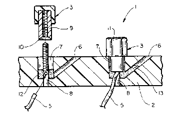
Figure 1 is a per~pective view of a terminal block
having four connection means; and
Figure 2 is a longitudinal partial cross-section through
a part of the b~ock of Figure 1.
~,
o~
MP1~ 4 O-CA
Detailed Description of the Drawinqs
Figure 1 shows a terminal bloclc 1 comprising a housing 2
having four connection means for t~o pairs of drop-wires. A
cap 3 is shown received on a binding post and partially
within a first aperture, the binding post and first aperture
therefore being invisible in the drawing. A second aperture
4 for receiving a drop-wire 5 is shown, and it can be seen
that aperture 4 communicates with the aperture within which
a part of cap 3 is received. When cap 3 is tightened down
to the position shown, a bottom edge of the cap can contact
a core of a d.rop-wire within an aperture 4. A third aper-
ture 6 also communicates with the aperture within which a
part of the cap 3 is received r and it is into this third
aperture 6 that sealing material may be displaced when the
cap is screwed down onto the binding posts.
The third aperture 6 is shown on a top face of the
housing 2, but it may appear at any surface of the housing,
or be blind and therefore not appear at all. For example,
it may appear at the back (i.e. at a face opposite to that
of aperture 4) or it may appear at the underside of the
~lock.
~ Figure 2 is a partial cross-section through a part of
; the bloc~ of Figure 1, showing two first apertures 7 having
binding posts 8 therein~ The cap 3 has a skirt or other
part 9 that will be received within -the first aperture 7, a
bottom edge of which part bears an insulation displacing
cutting edge 1~. A drop-wire 5 is positioned through the
second aperture 4 tsee figure 1) and -through a hole in the
~L3~8(~
MP12~0-CA
-13-
binding post 8 as indicated by the arrow leading from the
drop-wire 5 in figure 2. alternatively, the second aperture
4 may rer.ain the drop-wire 5 alongside the binding post.
The flrst aperture 7 contains a sealing ma-terial 12 such as
a gel, which can be seen, by comparing the left- and right-
hand halves 1 of figure 2, to be displaced into -the third
aperture 6 on installation of cap 3. When the cap 3 is
unscrewed, the part 9 thereof preferably drags the sealing
material out of the third aperture 6 from the position indi-
cated as 13. Preferably when the cap is fully removed from
the binding post, the sealing material is substantially
cleanly left behind in the first aperture 7 as shown in the
left-hand half Oe the figure. Alternatively, the cap and
apertures may be so designed that the sealing material is
retained on or in the cap.
.... .,..,.... ,..,
... ......