Note : Les descriptions sont présentées dans la langue officielle dans laquelle elles ont été soumises.
1304948
-- 1 --
PROCESSES FOR MAKING JEWELLERY COMPRISING ONE
OR MORE ROWS OF STONES, AN~ JEWELLERY OBTAINED
BY THESE PROCESSES
The present invention relates to processes
for making jewellery comprising one or more rows
of stones, and to the jewellery obtained by these
processes.
It is an object of an aspect of the present invention to
provide processes for making jewellery comprising
a number of precious stones, and in particular bril-
liants, set on a support made of precious metal,
in particular gold, to produce jewellery, for example
10 rivières of diamonds or diamond pavings comprising
one or more rows of precious stones, very close
to one another, with gaps between stones of the
order of 0.05 mm, this rendering them very bright
with a fine surface appearance.
The fixing of the precious stones on a gold
support, particularly the fixing of small-sized,
closely set diamonds, raises problems which are
very delicate to solve.
The housings for the stones must be machined
20 with very high precision both in their dimensions
~nd in their respective positions and, taking into
account the very high value of the precious stones,
the means for fixing them must be very reliable.
Moreover, the fixing means must not be too visible
25 from the outside in order not to spoil the aesthetic
appearance of the jewellery.
Numerical-control machine tools exist which enable
supports of precious metal to be automatically
machined with very high precision, of the order
30 of 0.01 mm.
It is an object of an aspect of the present invention to
provide processes for automatically prefabricating
in the factory supports made of precious metal,
particularly gold, of various shapes, for example,5 rings, bracelets, pendants, etc..., so that such
q~
130~948
supports are ready to receive one or more rows of
precious stones, disposed very close to one another, so
that these stones are very easy to fix by setting and so
that the fixing claws are hardly visible on the outside
face.
At the present time, precious stones are, in the
majority of cases, set on the jewellery.
French Patent No. 1 506 317 to H. FAVRE describes a
process whereby stones are set on a metal foil by means
of a setting tool comprising a plurality of heads which
penetrate in the metal, detaching a portion which they
push against the stone in order to form a claw.
French Patent No. 2 386 281 to BOWY, published
November 3, 1978 describes a process wherein equidistant
transverse grooves are cut in a gold support, then a
bore is drilled between each pair of grooves, whose
diameter is greater than the distance between grooves,
this resulting in four projecting catches which are then
bent over.
U.S. Patent No. 2 749 597 to Walter FUS describes a
process for manufacturing annular jewellery. The stones
are set between two rings which each comprise an inner
groove and the two rings are connected together by
welded crosspieces.
French Patent 80 04057 to DIAMANT APPLICATIONS
published September 1981 describes processes for
industrially manufacturing jewellery whereby the stones
are placed in position by clipping each stone in a
housing thanks to an elastic deformation of metal claws.
The objects of the invention are attained by means
of a process for making jewellery comprising one or more
rows of stones set in a support made of precious metal,
said process comprising the following operations:
~S
1304948
- one or more rows of cylindrical housings
extended by a conical seating and by a counter-bore,
are machined in said support;
- very thin metal bridges which separate the
juxtaposed housings are cut out, with a rotating
mill, over a height equal to that of said cylindrical
housings, with the result that each housing remains
surrounded by islets of metal, uniformly distributed
over its periphery;
- a stone is placed in each housing, said stone
abutting on said conical seating;
- and said stone is set by means of a hollow-
headed tool, which is applied axially on said islets
to deform them permanently by buckling.
According to a known embodiment, the diameter
of each cylindrical housing is slightly smaller
than the diameter of the circle circumscribed about
the stone and there is cut out on the periphery
of each cylindrical housing and above the seating,
20 a peripheral groove of triangular section of which
the diameter at the bottom of the groove is greater
than the diameter of the circle circumscribed about
said stone~
In this embodiment, a process according to
25 the invention comprises the following operations
of:
- cutting out with a rotating mill the metal <~
bridges separating the adjacent housings on the
part located above the median plane passing through
30 the bottom of said groove, with the result that
there remain around each seating metal islets which
constitute claws common to three seatings which
each comprise a head and a curvilinear triangular
foot, of reduced section, defined by three sections
35 of groove which penetrate beneath said head, and
1:~04948
the circle inscribed inside said heads has a diameter
less than the outer diameter of said stone;
- engaging in each housing surrounded by said
claws a stone which pushes said claws outwardly
by permanent deformation in flexion of the feet
of said claws;
- and, when the three stones surrounding a
claw are in position, applying axially on the head
of said claw a hollow-headed setting tool in order
10 to deform by buckling the foot of said claw.
According to a preferred embodiment, if the
stones are disposed in quincunx over several rows,
said metal bridges are cut out with a mill rotating
at high-speed about an axis which is placed successive-
15 ly above each of the points lying at the centreof the triangles formed by the centres of each group
of three housings disposed in a triangle.
According to another preferred embodiment,
if the stones are disposed in quincunx over several
20 rows, the metal bridges are cut out with a mill
rotating at high speed about an axis which is placed
successively above each point equidistant from the
two centres of two adjacent housings and said mill
comprises a rounded inner cutting edge.
The invention makes it possible to obtain jewelle-
ry of the type comprising several rows of stones
disposed in quincunx which are set in a support
made of precious metal, by claws which have undergone
a permanent deformation.
This jewellery is characterized in that each
stone is surrounded by siX claws and each claw is
located at the centre of three stones and is common
to these three stones.
Each claw presents, in that part located above
35 the seating on which the stone rests, the form of
1304948
a concave, curvilinear, triangular prism, of which
the three side faces are constituted by three cylindri-
cal sectors.
According to a preferred embodiment, each claw
comprises a hemispherical head or a head in the
form of a convex, curvilinear trihedron, which sur-
mounts a foot of smaller section, having the form
of a concave curvilinear triangle which is defined
by three circular groove po~ions of triangular
10 cross section which penetrate beneath said head.
The invention results in jewellery comprising
a very dense paving of precious or semi-precious
stones set in a support made of precious metal,
for example rivières of diamonds.
The jewellery according to the invention compri-
ses stones preferably disposed in quincunx, each
stone being set by six claws and each claw is located
at the centre of three stones disposed at the vertices
of a triangle and it is common to these three stones.
This results in that each stone is set firmly
by six claws whilst having a reduced total number
of claws, hence a greater density of brilliants
and an improved aesthetic appearance.
The processes for manufacturing jewellery accor-
25 ding to the invention make it possible to prefabricate
supports in the factory on numerical-control machine
tools with the very high precision required both
for the implantation of the housings for each stone
and for the dimensions of these housings, such preci-
30 sion being of the order of a hundredth of a millimetre.
The curvilinear triangular form of the claws
obtained by the process of machining facilitates
the permanent deformation thereof by buckling and
leads to a~very reliable setting.
3S The proc-ss of setting by buckling the clsws
1304948
~,-
is particularly suitable for setting fragile stones,
such as emeralds or semi-precious stones as the
mechanical efforts causing buckling are essentially
applied on the claws without the stones being subjected
to dangerous stresses.
Another aspect of this invention is as follows:
Jewellery of the type comprising several rows of
stones which are set in quincunx in a support made of
precious metal, by claws which have undergone a
permanent deformation, wherein each stone is surrounded
by six claws and, each claw is located at the centre of
three stones to which it is common, and presents, in
that part located above the seating on which the stone
rests, the form of a concave, curvilinear, triangular
prism, of which the three side faces are constituted by
three cylindrical sector.
The invention will be more readily understood on
reading the following description with reference to the
accompanying drawings, in which:
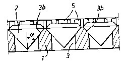
Fig. 1 is a transverse section through a piece of
jewellery according to the invention.
Figs. 2 and 3 respectively show a plan view and a
section along III-III of the first step of machining of
the support.
Figs. 4 and 5 respectively show a plan view and a
section along V-V of the support during the second phase
of machining.
Figs. 6 and 7 respectively show a plan view and a
section along VII-VII of a second phase of the machining
of the support in a variant embodiment.
Figs. 8 and 9 respectively show a plan view and a
section along IX-IX of a third phase of machining of the
support in the same variant embodiment.
Figs. 10 and 11 respectively show a plan view and a
section along XI-XI of a third phase of machining of the
support, in a variant.
I:S
~304948
6a
Referring now to the drawings, a piece of jewellery
according to the invention comprises a support 1 made of
precious metal, preferably gold. This support may for
example be a foil garnished with contiguous precious
stones 2, generally brilliants, and which may then serve
to make jewellery such as rings, brackelets, pendants,
brooches, etc.
The support 2 may also be constituted by the body
of the jewellery itself, for example by a gold ring or
bracelet or by a gold pendant or any other
B
J.304948
--7--
jewellery.
The jewellery according to the invention compri-
ses one or more rows of contiguous stones 2, the
gap between brilliants being of the order of 0.03
mm, with the result that the visible face is very
bright.
The stones 2 used for making this jewellery
are generally small-sized stones. These stones are
calibrated by passage through screens whose meshes
increase by 0.05 mm from one class to the following.
Series of screens may be used, having closer
mesh dimensions, which define granulometric classes
increasing by steps of 0.02 mm. In any case, the
precision on the outer diameter of the stones, which
constitutes the largest dimension, is therefore
very high, the tolerance being 0.05 or 0.02 mm.
Each piece of jewellery is composed of stones belon-
ging to determined granulometric classes. Each stone
2 is set in a housing 3 which comprises a conical
seating 3b, on which the stone abuts. The angle
of opening of this conical seating corresponds substan-
tially to the angle of the stones which is a
determined angle.
The Figures show embodiments in which the stones
are identical and are disposed in quincunx in parallel
rows, the centres of the stones being equidistant.
It is specified that these examples are not
limiting. The same jewellery may comprise rows of
stones of different size. The stones may be disposed
in curved lines, for example along arcs of circle.
The centres of the stones need not be equidistant.
The jewellery may comprise one or more rows
of stones. If it comprises several rows, the stones
are advantageously disposed in quincunx.
Each stone 2 is maintained in its housing by
, ~
1~04948
-8-
six claws 5 distributed regularly about its periphery.
Figs. 2 to 5 show the successive steps of a
first process for machining the support.
The support 1 which is to be garnished with
S stones, is placed on the work table of a numerical-
control machine tool which displaces the table beneath
a rotating mill or drill. This tool pierces through
the support 2 rows of cylindro-conical housings
3 which are equidistant and disposed in quincunx.
Each housing comprises an outer cylindrical
bore 3a whose diameter is slightly greater than
the upper limit of the class of granulometry chosen.
For example, if diamonds having a diameter of between
1.10 mm and 1.15 mm are chosen, bores 3a are machined,
15 having an outer diameter of 1.15 mm with a tolerance
of ~ 0.01 mm. The depth of the bores 3a is greater
than the thickness of the head of the stones, so
that, when the brilliants are placed on the conical
seating 3b, their upper face lies below the upper
20 face of the support 1, as shown in Fig. 1.
Each housing also comprises a conical seating
3b of which the angle of opening corresponds to
the angle of cut of the stones. Finally, each housing
3 comprises a cylindrical bore 3c which may open
25 out on the rear face of the support, as shown in
Fig. 2.
In a variant, the bore 3c may be a blind bore.
It suffices that the depth of bore 3c be greater
than the height of the stones.
The cylindro-conical housings 3 are disposed
in quincunx and their respective positions are such
that the bridges of metal which separate two adjacent
housings are very thin webs having a thickness of
the order of 0.05 mm.
i304948
By machining the housings 3 on a numerical-
control machine tool, the very high precision necessa-
ry in the dimension of the bores and in the implanta-
tion thereof is obtained. The tool may also be orien-
ted perpendicularly to the front surface of thesupport l. The quincunx arrangement enables a greater
density of brilliants per surface unit to be obtained.
Figs. 4 and 5 respectively show a partial plan
view and a section along V-V of the support l during
the second machining phase.
The support l is still disposed on the work
table of a numerical-control machine tool, on the
tool-holder of which is mounted a tool 6 which rotates
about an axis x-xl. This tool is for example a cylin-
drical bar made of tungsten carbide comprising ahead 6a which is driven in rotation at very high
speed. This head comprises two cutting edges parallel
to the axis of rotation x-xl.
The work table is displaced to bring axis x-xl
successively above each of points O located at the
centre of each group of three housings 3 disposed
in a triangle.
Figs. 4 and 5 show the tool 6 positioned so
that its axis x-xl passes through point O located
at the centre of the triangle formed by the centres
l' 2 and O3 of a group of three housings 3.
In the precise case of the Figure, points l'
2 and O3 are disposed at the vertices of an equi-
lateral triangle of which point O is the centre.
Fig. 4 shows the two concentric circles swept
by the cutting head 6a. The height of head 6a is
equal to the depth of the bores3a, with the result
that the tool 6 removes the three metal bridges
intercalated between the three housings 3a centred
at l' 2 and O3.
13()4948
--10--
The outer diameter of head 6a is slightly greater
than the distance separating the centre O from the
three sides of the equilateral triangle.
After removal of the intercalated bridges,
there remains around each centre O an islet of metal
having the form of a curvilinear triangular prism
of which the side faces are concave and are constitu-
ted by three cylindrical sectors belonging to three
adjacent bores 3a.
Fig. 4 shows an intermediate step. For greater
clarity, the metal islets 5a, 5b, 5c, 5d are hatched
in Figs. 4 and 5.
Once the machining operations are terminated,
a stone 2 is placed by hand in each housing so as
15 to abut against the conical seating 3b~ In this
variant, the circle inscribed inside the six claws
which surround a housing, has a diameter greater
than the diameter of the stone which therfore pene-
trates freely in its housing. When the three stones
20 surrounding an islet of metal 5 have been placed
in position, a setting tool 7, shown in axial section
in Fig. 5, is applied on this islet. This tool is
in the form of a cylindrical punch terminating in
a hollow head 7a whose diameter is slightly greater
25 than the diameter of the circle in which the islets
5 may be inscribed. Tool 7 is applied with a suffi-
cient force to cause the islet 5 to undergo a perma-
nent deformation by buckling, with the result that,
when all the islets have been deformed, each stone
is set by six triangular claws formed by the islets
5. Each claw is common to three juxtaposed stones
disposed at the vertices of a triangle.
Each claw which is surrounded by three stones
with a ver~ small clearance, is deformed by buckling
solely in the axial direction as it is maintained
1304948
laterally by the three stones which surround it
and which prevent any deformation in flexion.
Figs. 6 to 9 show the successive steps of machi-
ning of a support l in a variant of the process.
The first machining step is identical and is
not shown. At the end of this first step, support
l is pierced with a plurality of rows of housings
3 disposed in quincunx. Each housing 3 comprises
an outer bore 3a, a conical seating 3b and a counter-
bore 3c, whose diameter is less than that of bore
3a and which may be a blind bore.
Contrary to the process according to Figs.
2 to 5, the diameter of the outer bore 3a is slightly
less than the diameter of the stones. For example,
for stones having a diameter of between 1.75 mm
and 1.80 mm, the bores 3a have a diameter of 1.65
mm.
Figs. 6 and 7 respectively show a partial plan
view and a view in section along VII-VII after the
second machining step. In the course of this step,
an inner groove 8 is cut out on the periphery of
each bore 3a and immediately above seating 3b, said
groove having a triangular section which extends
the slope of the conical seating 3b. The diameter
at the bottom of the groove 8 is larger than the
outer diameter of the stones. For example, for stones
whose diameter is between 1.75 and 1.80 mm, the
diameter at the bottom of the groove is at least
2 mm.
In this embodiment, the metal bridges separating
two housings 3a before the grooves 8 are hollowéd
out, are thicker. For example, for housings 3a having
a diameter of 1. 65 mm, the distance between centres
of two adjacent bores is 1.97 mm.
This distance is advantageously less than the
1304948
-12-
outer diameter of grooves 8 so that the grooves
of two adjacent housings intersect as shown in Figs.
6 and 7. References 8a represent the intersections
of groove 8 of the bore located in the plane of
section with the grooves of the bores located to
the rear of the plane of section.
The fact that the grooves intersect means that
the transverse sections of the feet of the claws
are sufficiently weak to bend laterally, to allow
10 the stones to pass, then to buckle during setting.
The grooves 8 are machined on a numerical-control
machine tool by means of a rotating mill which is
positioned successively in the axis of each of bores
3.
Figs, 8 and 9 show another step of machining
of a support 1 in the second embodiment. In the
course of this step, the support 1 still being on
the work table of the machine tool, a rotating mill
9 is mounted on the tool holder, which mill comprises
20 a milling head 9a having an inner edge 9b of rounded
shape, for example in the form of a quarter circle.
The height of the milling head is preferably equal
to or slightly greater than the distance separating
the median plane of the groove 8 passing through
25 the bottom of said groove from the outer face of
the support, with the result that the mill 9 removes
metal only above the bottom of the groove.
By displacing the work table, the support 1
is placed in successive positions where the axis
30 x-xl of the tool passes through points O located
at the centre of each triangle formed by the centres
l' 2 and O3 of each group of three bores 3 disposed
in a triangle.
Fig. 8 represents by broken-line circles the
35 circular traces of the tool 9 which removes the
~304948
metal bridges located between the bores and which
leaves metal islets 10a, 10b, 10c which are hatched
in order to render the drawing clearer.
Each metal islet which constitutes a claw com-
prises a hemispherical head 10a, 10b, 10c whichhas been cut out by the rounded edge 9b. This edge
surmounts a foot of smaller section which has the
form of a curvilinear triangle of which the three
sides are concave and are defined by three circular
10 groove sections 14a, 14b, 14c, of triangular cross
section which penetrates beneath the hemispherical
head.
The circle inscribed inside the six heads of
claws which is the primitive circle 3a, has a diameter
15 less than the outer diameter of the stone.
Once the machining operations are terminated,
a stone 2 is engaged in each housing 3 surrounded
by six claws. When the stone is being engaged, it
pushes claws 10a, 10b, lOc, etc... outwardly of
20 the housing 3.
The claws deform by flexion of the foot which
is the weakest and such deformation is permanent.
When a stone is placed in an adjacent housing,
said stone pushes the claws Iocated between the
25 two housings in opposite direction and said claws
are deformed again by flexion of the foot. The groove
14 located on the side where the first stone has
already been positioned, presents a clearance with
respect to this stone and enables the claw to
30 straighten up.
When the three stones surrounding a claw have
been positioned, the hollow end lla of a setting
tool 11 is then applied axially on the head of each
claw 10a, lOb, 10c,
This end lla is preferably in the form of a
1304948
hemisphere which follows the shape of the heads.
Thrust of the tool 11 provokes axial bucking of
the foot of each claw.
The grooves 14a, 14b, 14c which define a foot
of reduced section, facilitate, on the one hand,
the outward flexion of the claws when a stone is
engaged and, on the other hand, the buckling of
the foot. During the operation of setting by buckling,
each claw is maintained laterally by the three stones
which surround it, with the result that they cannot
bend laterally and an axial buckling is obtained.
It will be noted that the process of setting
by axial buckling is different from the processes
of setting in which the claws are bent down onto
the stones, as well as from the processes by clipping
in which the stones are driven between the claws
which deform elastically then resume their initial
position under the action of the elastic return
forces.
Figs. 10 and 11 show a second variant of the
embodiment of Figs. 6 to 9.
The first steps of machining are identical
to those of the preceding process, i.e., in a first
step, rows of cylindro-conical housings 3, disposed
in quincunx as shown in Figs. 2 and 3, are hollowed
out, then a groove 8 having a triangular profile
as shown in Figs. 6 and 7, is cut out on the periphery
of these housings.
Fig. 10 shows a partial plan view and Fig.
11 a section along XI-XI during the operation of
machining the metal bridges which separate the bores
3. This machining is effected by means of a rotating
mill 12, of axis x-xl, which comprises a milling
head 12a having an inner edge 12b of concave form.
The radius of tool 12 is greater than the radius
1304948
of tool 9. By successive displacements of support
1, mounted on the work table of the machine tool,
the axis x-xl of the tool is brought above each
point O, equidistant from each pair of centres l'
2 of two juxtaposed housings 3. Several successive
paths of tool 12 have been shown in Fig. 10 by dashed
circles.
After all the metal bridges have been removed,
there reamain between the housings 3 metal islets
10 13 which comprise on their top a dome formed by
three convex surfaces which define a cuvilinear
trihedron. At its base, each islet is defined by
three grooves 14 which are portions of three grooves
8 disposed as a curvilinear triangle, which penetrate
15 beneath the dome.
Figs. 10 and 11 show an islet 13 which has
been hatched to render the drawing clearer. As before,
a stone is then engaged in each housing 3, applying
it on the seating 3b then there is applied on each
20 islet 13 a setting tool having a hollow head in
which the islet penetrates and it is pushed sufficient-
ly to obtain permanent deformation by buckling of
the feet of the islets defined by the grooves 14.
According to this variant embodiment, each
25 stone is set by six claws 13, of curvilinear triangu-
lar form with convex faces which give the jewellery
an original aesthetic appearance. Each claw 13 is
common to three stones and is located at the centre
thereof.
Figs. 4 and 5, 8 and 9, 10 and 11 show the
machining of the bridges located between two rows
of housings.
If there is only one row and if there are several
rows as far~as the border rows are concerned, the
35 metal bridges which separate the claws are removed
1304948
-16-
by means of the same rotating mill 6 or 9 which
is positioned successively above points occupying,
with respect to the centres of the stones, geometrical
positions corresponding to the positions of points
O shown in these Figures.
In the case shown in Fig. l, the axis x-xl
of mill 12 may be positioned successively in line
with the axis of each bore 3.
Figs. 4 and 5 show claws having the form of
a curvilinear triangular prism of which the side
faces are concave and constituted over the whole
of their height by cylindrical sectors belonging
to three adjacent bores 3a.
In order to improve the aesthetic effect, it
is preferable to have claws with rounded head. To
this end, the upper part of each claw is machined
so as to have a downwardly tapering truncated form
of which the base is inscribed inside the curvilinear
triangular section of the triangular prism.
Such machining may be effected on a numerical-
control machine by means of a rotating mill having
an oblique cutting edge which is successively posi-
tioned in the axis of each claw. It may also be
made by circular interpolation with a rotating mill
in the form of a truncated punch of which the axis
of rotation describes a circle centred on the axis
of each claw.