Note : Les descriptions sont présentées dans la langue officielle dans laquelle elles ont été soumises.
PULLING OR LOADING VEHICLE W_TH
FRElE SPACE BETWEEN THE REAR WHEELS
The present invention relates to a pulling or loading
vehicle.
Pulling or hauling vehicles have been used for decades,
particularly in the form of tractors for agricultural
or forestry purposes. Although the requirements made on
such vehicles and the uses thereof have undergone
considerable changes, the basic construction thereof has
essentially remained unchanged.
Although originally a relatively high tractor weight was
desired, because they were used purely as pulling
vehicles and consequently the rear axle had to be
ade~uately loaded, of late and in particular following
the occurrence of tools or implements to be directly
suspended on the tractor, the weight of the tractor and
the weight distribution have proved disadvantageous. By
means of three-point suspensions or hydraulic lifting
devices, numerous means are now coupled to the rear of
the tractor and during operation can be lowered onto the
ground or raised when moving. These implements or tools
in part have a considerable weight and therefore lead to
an additional loading of the rear tractor axle.
Xf very heavy tools are hung on the rear of the
tractor, there is a risk that this will cause leverage
and consequently an unfavourable weight dis~lacement,
which can bring about a lifting of the front axle. The
presently conventional countermeasure comprises fitting
additional weights in the vicinity of the tractor front
axle, so that the front axle load is raised. Although
this is able to stabilize the tractor and prevent a
lifting of the front axle, it simultaneously
considerably increases the total tractor weight and
cvnsequently causes a very considerable ground or soil
" ~3~5~G~5
pressure. ~ue to the great overall weight, it is
frequently necessary to have a four or all-wheel drive
in order to increase the tractive power, but this only
insignificantly improves the pulling capacity, because
in accordance with the short construction of such
tractors the vehicle weight is displaced to the rear
axle due to the pulling moment and the weight
distribution in operation.
As a result of the weight of the tractor and tools and
the consequent considerable loading in particular of
the rear axle, the soil is greatly compressed and
damaged along the wheel track. This is prejudicial to
the activity of soil organi~ms and bacteria and the
field is wheeled together, so that there is an
inadequate oxygen supply and a disturbed water
conservation of the soil. Due to the destroyed soil
capillarity, the water drainage under rainy conditions
and the rising of the water during good weather are
impaired. This excessive soil loading also leads to the
destruction of plant growth, the obtaining of a lower
yield and the necessitating of increased fertilizer and
pesticide application. This lPads to an additional
harming of the environment, which could be avoided by
the use of suitabIe txactors and tools. ~loreover, the
travelling characteristics of vehicles designed in this
way are very unfavourable and dangerous. This more
particularly applies as a result of an inadequate
loading of the fxont axle and consequently to difficult
controllability of the vehicle, particularly when
travelling rapidly on roads.
The problem of the present invention is to provide a
pulling or loading vehicle, which ensures more
favourable travelling characteristics through a suitable
~3~ 5
2a
weight distribution and loading of the rear whPels, has
a limited overall weight of vehicle and tocls, whilst
causing limited soil loading in the case of high
manoeuvrability and small dimensions.
An aspect of the invention is as follows:
A pulling or loading vehicle, particularly a tractor,
comprising two front and two rear wheels; drive means
for driving at least said rear wh els;
a substantially rigid vehicle frame supporting the front
wheels of said vehicle and said drive means, said frame
having a front end and a rear end; and
wheel mounting means rigidly attached to said vehicle
frame Xor rotatably supporting said rear wheels of said
vehicle, said wheel mounting means comprising
longitudinally extending struts spaced outwardly from
said rear end and laterally spaced from each other,
thereby de~ining an open space between said rear wheels
in which auxiliary equipment for said vehicle can be
mounted.
By way of added explanation, the inventive pulling
vehicle according to an aspect of the invention has a
rear wheel fixture or mounting with two legs or
longitudinal struts. This rear wheel mounting
pre~erably comprises a transverse strut construction and
two U-shaped-arranged longitudinal struts carrying the
wheels~ It is preferably located in a substantially
horizontal plane and is oriented in such a way that the
transverse strut construction is fixed to the rear end
of the vehicle chassis and the two longitudinal struts
project rearwards laterally and parallel to the
direction of travel. The two rear wheels are fitted to
,;~ .
_.
~ ~3~5~5
2b
the free ends of these two longitudinal struts, so that
there is a free space or gap between the wheels. This
makes it possible to couple or hang a tool and/or other
implement to the vehicle in such a way that the centre
of gravity thereof is in front of or only just behind
the rear wheel axle line. This relieves the rear~wheels
and brings about an optimum weight clistribution. This
simultaneously offers completely
~.~,
~3t155~5
-- 3 --
new possibilities ~or thP use of tools or additional drive mKans. The
advantages brought about by the in~ention ~ore particularly become apparent
in the case of a short construction of the pulling vehicle, because then the
risk of a lifting of the front axle is particuLarly acute. This i~proved
axle load distribution also increases safety th m~lgh an improved fast
travelling behaviour of the tractor, particu~ly on roads.
Enbodiments of the invention are described hereinafter relative to the
drawings, wherein ~how:
Fig. 1 A conventional tractor.
Fig. 2 An inventive tractor with U-shaped rear wheel mcunting.
Fig~ 3 A tractor with a U-shaped rear wheel mounting and a three-point
suspension.
Fig. 4 A tractor with a U-shaped rear wheel mcunting and an
a~ditional driving caterpillar.
Fig. S A tractor with a U-shapad rear wheel mcunt m g and a saddle coupling in ~rant of the rear wheel axle line.
Fig. 6a A tractor with a U-shaped rear wheel mcunting and a double
cable winch suspended between the rear wheels.
Fig. 6b A tractor with a U-shaped rear wheel mcunting and a fertilizer
distributor fitte~ between the rear wheels.
Pig. 6c A tra~tor with a U-shaped rear wheel mcunting and a field
spr~y~r su~pend~d betwe2n the rear wheels.
Fig. 7 A tractor with a U-sh~ped rear wheel mcunting and a rear
loading shc~vel.
Fig. 8 The rear ~heel mountmg with an inte~rated drive in
cr~ss-section.
~3~S~
-- 4 --
Fig. 9a A longitudinal section through a rear wheel drive with a
chain and a planetary gearing down means m t0grated into the
wheel.
Fig~ 9b A longitudinal section thrcugh a rear wheel drive with a
chain and a gearing down by means of an internal pinion.
Fig. 10 A longitudinal section -through a rear wheel driv~ with gears.
Although herein æ ter reference i essentia1ly only made to a tractor, the
inventive vehicle construction can be used for all types of pulling and
loading vehicles.
Fig. 1 is a view from above of a conventiQnal tractor. It is possible to
see the chassis with the engine asse~bly 5, the solid rear axle 8 and the
re æ wheel drive block 9. The comstruction o~ such a tractor leads to an
uneven weight distribution on the axles with approximately a third of the
weight on the front axle and two thirds of the weight on the rear axle 8.
As can be gathered fm m fig. 1, if e.g. a three-point suspension with three
hinged brackets 17 i~ pnoYided, whereby said brackets can be moved vertically
by a not shown hydlaulic lifting d~vice, thRn same must necessarily be
positioned ~ the rear wheel drive block 9. Howev ~, ~ leads to an
additional weight displacement, because a tooI fixed to said hinged brackets
17 exerts a lever~ge with respect to the rear axle, front wheels 2 are
relieved and~conseguently additional weight is applied to the rear wheels 3.
Thu~, the bearing p~ints of the rear wheels 3 eKert a considerable pressure
on the soil and soil strucbure, i.e. both the capillarity of the soil and
small and very small organismæ are destroyed. ~he additional weights 19 in
the fr~nt of ~he tractor o~ten provi1ed for increasing the stability or
Dmproving the æteerability of the tractor do not prevent the loading o~ the
re æ wheels 3 and fail to relieve the latter. In fact, the overall weight
of the tractor~is mcreased, so that additional soil loading occurs.
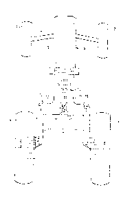
Fig. 2 dlagramm~tically shows from abcve a tractor according to the invention.
In the same way as with conventional tractors, there is an engine ass ~ ly 5
with an engIne 7. A gear block 14 is diagrammatically indicated. The vehicle
~ ,
~.
~3~
-- 5 --
can either have a rear wheel or an all-wheel drive. Contrary to the
conventional pr~cedure, the two rear wheels 3 are not mcunted on a rigid,
CommQn drive axle, but on two lateral legs or longitudinal struts 11 of a
rear wheel maunting or fixture 10. A conventional axle arrangement
conse~u~ntly does not exist and instead said mcunting fulfils the functions
of a chassis and an axle. This wheel mounting 10 preferably CQntainS a
transverse strut construction 12 and two lateral longitudinal struts ll and
in general has a substantially U-shaped configuration. The transverse strut
construction 12 is rigidly connected to the rear ~ 13 of the vehicle
chassis. Both t~ transverse strut construction 12 and the longitudinal
struts 11 are internally hollow and constructed as a torsion-resistant, load-
carrying casing. The two rear wheels are mounted on the free ends of the
l~ngitudinal struts 11 and are driven by means of a drive 15 prov;~ed in
the interior of the wheel mKunting 10. The space in the transverse stnut
constr~ction 12 offexs sufficient ~pace for a transverse gear 14 (spur bevel
gear and differential). The width of the transverse strut construction 12
determines the spacing o~ the rear wheels 2. As a result of the lateral,
spaced, rearwardly directed longitudinal struts 11, there is a free space 1
between the rear wheels and sai~ space is appr~ximately rectanguLar in plan
view in the represented embodiment. The U-shaped wheel m~unting 10 is
preferably horizontal, i.e. apprQximately parallel to a horizontal plane.
The two lRngitudinal struts or legs 11 are so long that their attachmen-t
point to the vehicle chassis or to the transverse strut construction 12 is
in f~ont of or in the vicinity of the leading edges of rear wheels 3. The
free space 1 between the rear wheels can be detenmined by a suitable choice
of the length of the legs 11 and by their lateral spacing. There are
practical l~nits as a result of the loads occurring when travelling and the
necessary materi~l thickness of the wheel mcunting 10. The wheel base is
roughly the same as in ccnv~ntional tractors, although the rearwardly
projecting longitudinal struts or legs ll are prw ided. This is possible,
bscause hithsrto the clutch case was lengthened and furthsr components wers
m~de too large in older to obtain the necessary overall tractor length.
However, as a cGmpact constN ction is aimed at in the case of the inventive
tracto~, thers is no nesd for a large clutch case and consequently the
standard wheel base is obtained. The free space 1 between the rear whsels
permits the fitting of tools or other means, as well as the coupling of
a1ditional implements or trailers. This construction permits a displacemen-t
~3~ 5
-- 6 -
of the centre of gravity of the thus provided tools or wei~hts in the
direction of travel and consequently leads to a more uniform weight
distribution on the front and rear axles of the vehicle.
Fig. 3 shwws an embodiment of a tractor with a three-point suspension for
the fitting of e.g. agricultural tools. Three hinged brackets 17 are fixed
in articulated manner to a support profile 16. A comparison with fig. 1,
which shcws a conventional tractor with three-point suspension, reveals that
in the case of an identical wheel axle positioning of the not shown tools
fixed to the free enhs of the hinged brackets 17~ longer hinged brackets are
used in the case of the inventive tractor. This has the advantage that a
much greater freedom of movement is obtained, i.e. both the lateral swinging
out possibility and the vertical movement are increased. This makes it
possible to raise long tools or tool combinations by means of a not shown
hydraulic lifting means, which was hitherto not possible due to inade~uate
freedom o~ movement. The use of long hinged brackets in the case of
conventional tractors would have led to the tools being positioned well
behind the vehicle, so that the manoeuvrability and travelling stability
would have suffered.
Fig. 4 shows an embodiment of a tractor with a novel drive possibility for
the use thereof in the case of higher hauling loads. A driving caterpillar
20 is coupled to the rear end 13 of the vehicle chassis and is essentially
Jocated between the two rear wheels 3. Use is e.g. made of a thrust unit in
accordance with European patent application 85107772.1 with the drive also
described therein. This cate~pillar or thrust unit 20 is so positioned in
the longitudinal direction of the vehicle, that its central axis coincide~
or virtually coincides with the rear wheel axle lme. This ensures that the
oontrollability of the vehicle is not impaired, because when steering and
turning the vehicle both thR rear wheels and also the driving caterpillar 20
are essentially located an a conmon line at right angles to the direction of
travel. Through the use of such a caterpillar 20 the relatively lightweight
tractor can be reequipped in a v~ry short time to a powerful tractor with a
~ery high pulling capacity. This leads to considerable advantages particularly
in agriculblre which re~uires tractors to carry out many different tasks and
consequently hitherto tWQ tractors have usually been needed to ccver all
these tasks. As a result of the additional bearing surface of the driving
3L3~ 5
-- 7 --
caterpillar 20 the maximum soil pressure loading the rear wheels can be
reduced and slmultaneously the pulling capacity increased, which is
particularly advantageous in the case of ploughs, harrows or ~hen carrying
out heavy harvestmg work. For difficult tasks, such as e.g. seedbed
preparation, a compression of the soil can be avoided thrcugh the use of the
caterpillar. As the caterpill~r can be constructed with a total height of
only roughly 50 om, it is possible to e.g. addition,ally use tools such as
three-point suspensions, trailer ccuplings, rear loading shovels, etc.
Fig. 5 sh~ws the object of the invention with a saddle coupling 22. The
advantage of the inventive rear wheel fixture or mounting is that heavy two-
wheel -trailers, such as e.g. loaders, are not as hitherto located behind the
rear wheel axle of the tractor and are instead positicned abcve the same or,
as shcwn in fig. 5, are coupled and supported upstream of the driving axle
line 8. This enables the pulling tractor to take up a much higher saddle
load without the rlsk of relieving the front axle 4 and thereby making the
tractor uncontrollable. It is also possible to relieve the trailer axle, in
that there is a load transfer to the tractor. This imprcwed axle load
distribution increases the travelling safety due to imprcved travelling
characteristics and braking pcwer of the tractor when travelling rapidly,
particularly on roadsO
Figs. 6a, 6b and 6c show an inventive vehicle with fitted tools. It c3n be
seen that the free space between the rear wheels 3 can be used for the often
voluminous and heavy tools. A double cable wincA 24J sucA as is e.g. used
in forestry, is fixed by means of a suspension mechanism 25 to the rear
tractor end 13. The centre of gravity of the often heavy winches is locate1
in fr~nt of the imaginary rear wheel 3xis and leads to a unifo~m weight
dis~ributic~ ~n thR frcnt and rear wheels. This simultaneously le~ds to an
improved transfer of the pulling load to the prime mover, so that in use a
much higher torque than hitherto can be transferred via the wheels, which is
partic~larly im~ortant in the case of heavy pulling loads or when travelling
uphill. '
~nother possible use is shown in fig. 6b, where a fertilizer distributor 27
is positioned between the two r~ar wheels 3. Distributor 27, which often
weighs over 500 kg when loacled, no longer has to be fitted, as hitherto, well
55~
behind the wheel axle. This also obviates the additional weights 19 (fig. 1),
which norna~ly have to be fitted to the front 6 of the tractor, because
there is no leverage with respect to the rear wheel axle due to the forwardly
displaced positicn of the distributor centre of gravity when travelling~ The
weight of the fertilizer distributor acts directly on or upstream of the axle
of the re æ wheels, which simultaneously leads to good travelling
characteristics.
In a simil~ manner it is possible to fit a field sprayer or sprinkler 29 to
the tractor, as shown in fig. 6c. The spraying liquid container 31 with a
y city of a few hundred to over one thousand litres is favourabl~ positioned
betwean the rear wheels 3. Apart fmm the soil pressure reduction caused by
the improved weight distribution, it is also possible to r~duce the over~ll
length of the tractor with fitted fieJ~ sprayer compared with conventional
ve~icle-tool ccmbinations, so that improved manoeuvrability is achieved.
ed with the hitherto used vehicles with loading bridges or si~ar
structures for fitting implements over the r~ar wheel axle for i~proving the
load distribution, the inventive ccnstruction leads to a much smaller
overall height, in that the space between the large rear wheels is i~eally
utilized.
Fig. 7 shows an inventive tractor with a fitted rear loading shovel or
bucket 33. Such a loading shovel installation behind the tractor has not
hit~erto been possible due to the axle block 9 (fig. 1). The disadvantageous,
conventional frGnt loader can ncw be replace~ by a better and more efficient
cQnstruction. 8y means of a fitting device 34 a hydraulically movable
suspension means 35 can be fixe~ to the rear of the tractor chassis. For
increasing adhesion an reducing soil or ground pressure, it is possible to
use simultaneously wi~h said loading sh~vel a driving caterpillar 20 (fig. 4).
This makes it possible to carIy out excavation work in much the same wa~ as
with construction machlnes. Such work ~as not possible with conventional
front 1O3ders due to the loads caused by the weight distribution. Compared
with front loaders, it is possible to use much laryer shovels or bucXets and
therefor~ the lo~ding or cubic metre capacity can be significantly increased.
The free space be~ween the rear wheels permits ~he coupling of further
auxilia~y means or tools, as well as trailers or other machines. It is also
~3~5S~
possible to mcunt any other bulky loads, tools or loading pla fforms between
the rear wheels. T~e fitting devices, couplings or other auxiliary means
can be pr~vided directly on the vehicle chassis or on the wheel mKUnting 10.
Obviously wheel mK~nting 10 need not have a U-sh~pe. Thus, in particular
the transverse strut construction can be omitted and there can be two legs
11 e~anating fmm one point. F~r special uses the transverse strut
construction 12 can be made even wider and more stable, so that the rearwc~rdly
projecting longitudinal struts 11 are located on the ~utside of the rear
wheels and their wheel axles 11 are mcunted in said struts 11 and directed
inwands. This makes it possible to also fix or support tools or auxilia}y
means on the autside of the rear wheels an said struts 11. The free end of
the longitudinal struts 11 can also be forked, the rear wheels in each case
being located between said forks.
In on1er to achieve a balanced loalmg o~ the longitudinal struts or legs ll
the wheel mounting 10 can also be inclined with respect to the horizontal
position and can e.g. slcpe rearwards. In the case of a corresponding
chassis design, the transverse strut construction can be eliminated or
integrated into the chassis and the longitudinal struts can be directly
mounted on the latter.
A pcssible drive 15 for the rear wheels 3 is diagrammatically shown in fig. 8.
I~ the interior of the transverse strut construction 12 is located a
transverse gear (spur bevel gear and differential) 18, which is connected
by means of a driving shaft 40 and a gear-shift mechanism 14 to motor 7
(cf. fig. 1)~ By m~ans of shafts 38 and further drive elements 39, preferably
a chain drive, ~he two raar wheels 3 are driven. A gearing down means 42 is
provided on each of the e~ds of the longitudinal struts 11. This gearing
down mean~ is preferably ~rranged in such a way that it projects into the
free area o~ rear wheels 3.
Fi~s. 9a and 9b shaw two possible variants of the chain drives 41. As the
longit~dinal struts 11 are exposed to considerable lo~ls, particularly when
travelling ov~r uneven gr~ and cons~ently tosion ar~d twisting can occur,
it is advantageals to use chain drives. This m~lces it possible to avoid or
caT~ensate mschanical loading ~ transferring forces fmm shafts 38 to the
~3~55~
-- 10 --
reax wheel axles 8. In addition, such chain drives have relatively limited
force or power losses of approximately 1~. It is possible to use chains
with internal pinions (fig. 9b) or a planetary gear (fig. 9a).
In the case of adequate strength of the casing wall of the longitudinal
struts 11, it is also possible to use a gear dri~e 42 for driving the rear
wheels 3, as shown in fig. 10. The force is txansferred from shafts 38 to
rear wheel axles 8 by means of a plurality of spur gears 45.
Another variant of the invention makes use of a hydrostatic drive for the
rear wheel~ 3 or, in the case of a fGur-wheel drive, also for the front
wheels. The necessary connecting lines are located in the interior of the
rear wheel mounting 10 or pass along the same to the corresponding gearing
dcwn means 42.
Preferabl~ both the gear case and the rear wheel mcunting 10 and drive 15
have a lightweight construction, so that the overall weight of the vehicle
is low. As the weight distribution does not, as hitherto, occur on the rear
wheels as a result of the inventive rear wheel mcunting 10, a low vehicle
weight does not impair the pulling capacity. The aorementioned possibili~y
of an additional thrust unit is possible for læge pulling capacities.
, .
'
,