Note : Les descriptions sont présentées dans la langue officielle dans laquelle elles ont été soumises.
<,
BACKGROUND OF THE INVENTION
1. Field of the Invention
This invention relates to measurement of the liquid
flow velocities and liquid mass flowrates in a multiphase
flow containing at least two liquid phases. As used
herein the term "phase" is intended to refer to separate
immiscible liquid phases such as oil and water as well as
liquid and ~as phases. As used herein the term
"multiphase" is intended to refer to a mi~ture including
at least two such phases.
Determination of mass flowrate of components ;n a
flow requires a knowledge of the respective flow velocity
of each phase. As used herein the term "velocity" is
intended to refer to mean flow velocity in the flow
direction, for example along a tube. Hitherto the
accurate measurement of flow velocity of liquid phases in
a flow has proved difficult and has hampered the
development of mass flowra~te measurement techniques.
2. Description of the Prior Art
Measurement of the mass flowrates of components of
flows containing several phases is desirable in many
fields ~ut is of particular importance in the oil industry.
~Crude oil production is normally accompanied by
gaseous hydrocarbons and water. These three components
are piped from the oil well as a multiphase mixture. The
mass flow rate measurement of the oil, water and gas from
individual oil wells is important ~or better reservoir
management, better production allocation, and optimisation
~ - 2 -
of total oil production over the field life. Normally,
the required accuracy of determination of mass flow of
each component is 5%.
Additionally, there is often a need to measure the
relative concentrations of oil and water in a flow after
separation of the gas and some of the water. This
measurement can present considerable practical difficulty
particularly where the densities of the 3i 1 and water are
the same or similar.
Current practice for the measurement of mass flowrate
of the components of oil well flows is to periodically
physically divert the well output to a test separator.
After separation the flow rate of each component is
measured with conventional devices such as orifice or
turbine flow meters. There are several inherent
disadvantages associated with this technique. Firstly,
accurate measurement requires stabilised well flow which
can take some time to establish. Often testing the output
of a single well may take a whole day. In addition, the
physical size of the separator and associated equipment
occupies significant space which can lead to increased
costs on off-shore platforms. Finally, in practice it is
not feasible to provide each well with its own test
separator system and often many wells share a common
facility. Continuous monitori~g of the output of each
well is therefore not possible.
Various techniques have been suggested for on-line
mass flow measurement Oe multiphase mixtures. Nost depend
- ~3~
on determination of the concentration of one or more of
the components coupled with a determination of either the
mean velocity of one or more of the components or the
total mass 1Ow of the mixture. ~oncentration measurement
by capacitance is described in a paper entitled "On-line
measurement of oil/water/gas mixtures using a capacitance
sensor" by Beck M.S. Green R.G., Hammer E.A. and Thorn R,
Measurement 3 ~1) 7-14 (1985). Measurement of component
concentration using a dual energy ga,~a-ray transmission
; 10 technique has also been described by the following:
Fanger U., Pepelnik R. and Michaelis W. - Determination
of conveyor-flow parameters by gamma-ray transmission
analysis, pp. 539-550 in Nuclear Techniques and Mineral
Resources 1977, IAEA, Vienna, 1977.
Michaelis W. and Fanger H.U.-Device for determining the
proportions by volume of a multiple-component mixture,
U.K. Patent Application GB2083908 A, 1982.
Abouelwafa M.~.A. and Kendall E.J.~. - The measurement of
component ratios in multiphase systems using gamma-ray
attenuation, J.Phys.E.: Sci. Instrum, 131 341-345
(1980).
Kendell E.J.M. - Gamma-ray analysis of multicomponent
material, U.K. Patent Application GB 2088050 A, 1982.
Tomada T., Xomaru M., Badono S., Tsumagari K. and Exall
D. - Development of gamma-ray oil/water/~as fraction
meter for crude oil production systems, Paper presented
at the International Conference on Industrial Flow
Measurement On-shore and Off-shore, 22-23/9/87, London.
Microwave measurement of component concentration is
also known from U.S. patent 4,301,400. Neutron inelastic
scatter techniques have also been used.
Velocity is usually determined by measuring the time
taken for the fluid to flow between two sensors, one
downstream of the other, by cross-correlation of the
output signals of the two sensors, and combining this
~3~5iS~
with the distance between the two sensors. This
technique is described in Beck M.S. and Plaskowski A. -
Cross Correlation Flowmeters, Adam Hilger, Bristol,
1987. Doppler measurements are an alternative techni~ue
to determine velocity and have been described by Stuchly
S.S., Sabir M.S. and Hamid A. - Advances in monitoring of
velocities and densities of particulates usin~ microwave
Doppler effect, IEEE Trans. Instrumentation and
; Measurement IM-26 (1~ 21-24. The mass flow of a two
component mixture such as oil and water can be determined
by a gauge depending on Coriolis force. This is
described by Liu K.T. and Revus D.E. - Net-oil computer
improves water-cut determination, Oil and ~as Journal pp.
41-45, 19 December 1988. None of these techniques fully
solve the requirement for accurate on-line determination
of mass flow rate of each separate component of a
multiphase flow.
SUMMARY OF THE INVE~TION
It is an object of an a~ of this invention to provide methods
and apparatus for measuring liquid flow velocity and mass
flowrates of a multiphase flow containing at least two
liquids which will at least ameliorate one or more o ths
above disadvantages.
Accordingly, in a first aspect this invention
consists in a method for measuring liquid flow velocity
of a multiphase flow containing at least two liquid
phases, said method comprising the steps Of:
(i) passing said flow through a tube;
- 5 -
-
9a3~
(ii~ measuring at a first location the intensities of
gamma-rays transmitted through a selected volume of said
flow at two different gamma-ray energies, at least one of
said gamma-ray energies having substantiall~ different
mass absorption coefficients in each of said two liquids
to obtain a time varying measurement indicative of the
ratio of the mass absorption co-efficients of the
selected volume at said energies;
(iii) measuring at a second location spaced from the
first in the direction of said flow the intensities of
gamma-rays transmitted through a corresponding volume of
said flow at said two different gamma-ray energies to
obtain a time varying measurement indicative of the ratio
of the mass absorption co-efficients of said
corresponding volume at said energies;
(iv) cross correlating the time varying measurements
obtained at said first and second locations to deri~e a
liquid flow transit time and
~v~ calculating s~aid liquid flow velocity from the
transit time and the ~spacing of said first and second
location.
In a second aspect this invention consists in an
apparatus for measuring liguid flow velocity of a
: multiphase flow containing at least two liquid phases,
: said apparatus comprising a tube through which said flow
is passed; first gamma-ray transmission means to measure
at a first locatio~ the intensities of gamma-rays
transmitted through a selected volume of said flow at two
- 6 -
~3~5~
different gamma-ray energies, at least one of said
gamma-ray energies having substantially different mass
absorption coefficients in each of said two li~uids to
obtain a time varying measurement indicative of the ratio
of the mass absorption co-efficients o:E the selected
volume at said energies; second gamma-ray transmission
means to measure at a second location spaced from the
first in the direction of said flow the intensities of
gamma-rays transmitted through a corresponding volume of
said flow at said two different gamma-ray energies to
obtain a time varying measurement indicative of the ratio
of the mass absorption co-efficients of said
corresponding volume at said energies; means to cross
correlate the time varying measurements obtained at said
first and second locations to produce a liquid flow
transit time and to calculate said liquid flow velocity
from the transit time and the spacing of said first and
second locations.
In a third aspect this invention consists in a
method for measuring the liquid mass flowrates of a
multiphase flow containing at least two liquid phases,
said method comprising the steps of:
(i) passing said flow throug.h a tube;
measuring at a first location the intensities of
gamma-rays transmitted through a selected volume
of said flow at two different gamma-ray energies,
at Ieast one of said gamma-ray energies having
substantially different mass absorption
','
~3~
coefficients in each of said two liquids to o~tain
a time varying measurement indicative of the ratio
of the mass absorption co-efficients of the
selected volume at said energies;
~iii) measuring at a second location spaced from the
first in the direction of said ilow the
intensities of gamma-rays transmitted through a
corresponding volume of said flow at said two
different gamma-ray energies to obtain a time
varying measurement indicative of the ratio of the
mass absorption co-efficients of said
corresponding volume at said energies;
: (iv~ cross correlating the tirne varying measurements
obtained at said first and second locations to
derive a liquid flow transit time and
~ v) calculating the liquid flow velocity from the
; transit time and the spacing of said first and
; : second location.
:: (vi~ determining the component fractions of each liquid
phase in said flow and calculating each liquid
mass flowrate from said llquid flow velocity and
: component fractions.
: ~
: In~a fourth aspect this invention consists in an
~apparatus for measuring the liguid mass flowrates of a
multiphase flow at ~lea~st two liguid phases, said
apparatus comprising:
a tube through:which~said flow is passed; first
: gamma-ray transmission means to measure at a first
: - 8 -
s
location the intensities of gamma-rays transmitted
through a selected volume of said flow at two different
gamma-ray energies, at least one of said gamma-ray
energies having substantially different mass absorption
coefficients in each of said two liquids to obtain a time
varying measurement indicative of the ratio of the mass
absorption co-efficients of the selected volume at said
energies; second gamma-ray transmission means to measure
at a second location spaced from the first in the
direction of said flow the intensities of gamma-rays
transmitted through a corresponding volume of said flow
at said two different gamma-ray energies to obtain a time
varying measurement indicative of the ratio of the mass
absorption co-efficients of said corresponding volume at
said energies; means to cross correlate the time varying
measurements obtained at said first and second locations
to produce a liquid flow transit time and to calculate
the li~uid flow velocity from the transit time and the
spacing of said first and second locations;
: 20 and m~ans to determine the component fractions of
each liquid phase in said flow and calculate each liquid
mass flowrate from said flow velocity and component
fractions.
For preference the cross correlation is performed
in respect of a time varying measurement of
: ln(I'/IO')
, R =
: .ln(I /Io~)
.' :
:: :
~'
~3C~
where
I' = intensity of gamma-rays of a first energy
passing through the selected volume of flow
Io' = intensity of gamma-rays of the first energy
passing through the selected volume with
the tube empty
I" = intensity of gamma-rays of a second higher
energy passing through the selected volume
of flow
Io" = intensity of gamma-rays of the second
higher energy passing through the selected
volume with the tube empty,
The selected~volume of the ~flow can vary from a
relatively narrow volume across the tube to a volume
; : including substantially a full cross-section of the tube.
~. ~
; In~the measurement of mass flowrates the component
fractions~of each liquid phase are preferably determined
by means of the dual energy gamma-ray transmission
technique which will be described below.
The invention~will now be described, by way of
: : e~ample only, with ~reference to~the accompanying drawings.
BRIEF DESCRIPTION OF THE ~RAWINGS
Figure 1 is a~schematic sectional elevation o a dual
~ ~ :
energy gamma-ray transmission assembly forming part of an
` ~ apparatus according to this invention;
-- 1 0
~3~
Figure 2 is an end elevation of the assembly shown in
Figure l;
Figure 3 is a schematic block diagram of the signal
processing equipment forming part of the apparatus
according to this invention;
Figure 4 is a view similar to Figure 1 showing a
first alternate embodiment of the dual energy gamma-ray
transmission assembly.
Figure 5 is a view similar to Figure 1 showiny a
second alternate embodiment of the dual energy gamma-ray
transmission assembly.
Figure 6 is a view similar to Figure 1 showing a
third alternate embodiment of the dual energy gamma~ray
transmission assembly.
Figure 7 is a view similar to Figure 1 showing a
fourth alternate embodiment of the dual energy gam~a-ray
transmission assembly.
DESCRIPTION OF THE PREFERRED EMBODIMENTS
In the following description the invention is
described with reference to its application to a flow
contalnlng water, oil, and gas.
The measurement of gamma-ray absorption of a selected
volume of material at two different gamma-ray energies is
generally refe.rred to as a dual energy gamma-ray
transmission technique.
The dual e~ergy gamma~ray transmission technique
depends on the measurement of the transmission of
gamma-rays, at two different energies, through the sample
-- 1 1 --
.
~3~55i6~
.
to be analysed. If the gamma-ray path length in the
sample is constant, for e~ample, across a diameter such as
for oil, water and gas in a pipeline, calculations show
that the volume fractions of the three components can be
determined from the transmission measurements by solving
the equations
Iu e~p[ (~il Poil oil ~ater Pwater wate~ lgas ~as gas3] (1)
I" = I "e~p~ "p. ~ +~ "~ 2 +~ " p X ) ] ~ 2 )
o oil oll oil ~ater ~ater water gas gas ga3
D = ~ ~ ~x ~3)
oil water gas
where: -
I',Io',I",Io"
are as defined above, and
~water mass absorption co-efficient for water o
. ~ gamma-rays of the first energy
~water mass absorption co-efficient for water of
gamma-rays of the second energy
~oil mass absorption co-efficient for oil of
gamma-rays of the first energy
~oil = mass absorption co-eficiqnt for oil of
gamma-rays of the second energy.
D = in~ernal diameter of the pipe,
x ,x ,x = length of respective component
oll water gaR transversed by khe gamma-ray beam in the
pipe
;
!` Poil~Pwater~Pgas = respective densities of
- 12 components
.
~gas'~gas" = respectively mass
absorption co-efficients
for gas of gamma-rays of
the first and second
energies.
These eguations can be solved to give volume
fractions of:
~ oil = _oi1 water = water and gas = g
; The velocity of the gas bubbles can be de~erminèd in
a known manner by cross-correlation of the detected
intensities of transmitted gamma-rays. This requires only
single energy gamma-ray transmission systems, spaced apart
along the flow, however the measurements at one of the
energies of spaced dual gamma-ray transmission systems can
be used or even a dual energy system and a spaced apart
single energy system can be used. The time delay
determined by the cross correlation, and the distance
20~ ~between the gamma-ray beams from the two systems~along the
pipe, are combined to give the velocity of the bubbles of
. :
gas.
The velocity of the liquids (oil and water~ will
often be less~ than that of the gas. It is unlikely that
the velocity of the liquid (oil and water) can also be
obtained~from the correlation techniques described in the
previous paragraph because the main changes in transmitted
intensities are~due to changes to the bulk density of the
: ~ ,
oi1/water/gas~mi~ture.~ That is, due to changes in the
overall gas bubble volume. Hence the much smaller changes
,: :
~ 13 -
:
, . . . .
~3~5~
..
in density of the oil/water liquid are likely to be masked
by the much larger changes in gas volume.
This invention proceeds from the realisation that a
specific use of the detected gamma-ray intensities
measured in dual energy gam~a-ray transmission techniques
provides a measurement which is sensitive to the weight
fraction rat:io of oil to water and substantially
insensitive to variation of gas volume in the three phase
mi~ture; and that this measurement can be used to
determine the velocity of the oil and water mi~ture.
The mathematical basis for the invention can be
summarised as follows.
Consider the general case of dual energy gamma-ray
transmission but expressing the equations differently than
in equations (1) to (3) above. The weight fraction C of
; . each component, and the ratio R, are given by
oil water~Cgas = 1 (4)
~: ln(~
R = ~5)
ln(I /lo)
The mass absorption coefficients ~' and ~"
~: respectiv~ly of the lower and higher energy gamma-rays in
the three phase mixture of oil, water and gas are given by
:
- 14 -
s~
= ~oil Coil~water Cwater+~gas Cgas ~6)
~oil Coil+~water Cwater~gas Cgas (7)
Equations (4~ to (7) can be combined to give
C ~R~ '~ ) + [ ( ~ C }t8)
o~ater water ~as water ~as water_ ~as
oil water . oil water
w2ter {~oil R g i~ Ygas ~oii ) (~gas ~oil )] gas}(9)
(~oil ~~water ) R(~oil ~water )
The gas weight fraction Cgas in equations ~8) and
(9) is small compared with the oil and water weight
fractions. It can be shown by substituting appropriate
values of parameters equations (8) and (9) that the oil
weight fraction COi1 and water weight fraction CWater
depend only slightly on changes to the gas. Hence C
; and CgaS are approximately~a function of R as given in
~equations (83 and (g). This relationship is substantially
unaltered even if there is no~gas present.
Thus R which can be determined exper-imentally
according to equation (5) provides a measure of COil and
,~ ~
~water-
~ Time varying measurements of R using a dual energy
gamma-ray transmission~;technique at ~wo locations spaced
;~ ~ apart by a known distance can be cross correlated to
provide a ~ransit time~between the locations. Transit
15 -
~ ~ :
~3~5~i
time and the spacing of the locations allows a calculation
of velocity of the oil water mixture. The mean velocity
of the mixture thus obtained is a sufficiently accurate
estimate of the separate oil velocity and water velocity
to give mass flowrate measurements of the generally
required accuracy.
From a knowledge of liquid velocity the mass
flowrates can be calculated by using the volum~ fractions
` obtained from dual energy gamma-ray transmission
measurements at one or both o the locations as described
above and the density of the oil and water in the flow
which are determined using known techniques. Gas veloclty
can be determined using the same system according to the
technique described above. Gas volume can be determined
from the gas component fraction, measured as described
ahove, and using a knowledge of temperature and pressure
the gas mass flowrate can be calculated. That is, an
arrangement comprising two dual energy gamma-ray
; transmission systems can be used to determine mass flow
rate of each component.
Figures 1 and 2 show a dual energy gamma-ray
transmission assembly 1 forming part of a first embodiment
of an apparatus to measure flow velocity and mass flowra~.e
of each component in an oil, water and gas mixture. The
; assembly 1 comprises a tube 2 through which the mixture 3
is passed. The tube 2 is provided with diametrically
opposed windows 4, 5 formed of a low atomic number
material so that low en rgy gamma-rays can pass
- 16 -
therethrough without substantial attenuation. The windows
must transmit a substantial fraction of the low energy
gamma-rays, and be able to withstand pressures up to 5000
psi and temperatures up to 150~C occurring in some
pipelines carrying oil, water and gas mi~tures. As an
alternative the whole pipe over the cross-section may be
made of the low atomic number materiaL. Window 5 is of a
larger size than window 4 to allow for some divergence of
a gamma-ray beam as it passes through the flow 3. Two
radioisotope gamma-ray sources 6 are located adjacent
window 4 and surrounded by shielding 7 of a suitable
gamma-ray absorbing material. The source is any suitable
radioisotope or combination of radioisotopes which produce
gamma-rays o two different energies with at least one of
the gamma-ray energies having substantially different mass
; absorption co-efficients in each of oil and water.
.
Suitable sources include:
(i) 24lAm and l33Ba which produce
gamma-rays with energies of 59~5 keV and
20 ; around 356 keV; and
(ii) 24lAm and l37Cs which produce
gamma-rays with energies of 59.5 KeV and
663 keV.
~: ~ (iii) 24lAm above fos small dlameter pipes by
utilising both the 59.5 keV and lower
energy emissions.
Other well known radioisotope sources emitting low
energy gamma-rays can also be used either with 24lAm
- 17 -
~L3~
or separately. It will be apparent that it is notessential for both of the gamma-ray sources to be
completely mono-energetic.
The gamma~ray sources are placed at the end of a
passage 8 in shielding 7 so that a relatively narrow beam
of gamma-rays 9 is produced.
A scintillation detector 10 is disposed adjacent
window 5 to detect the intensities of both energy
; gamma-rays in the beam 9. Suitable scintillators are
sodium iodide and other well-known scintillator
materials. For best gain stability, the scintillator and
photomultiplier are temperature controlled to within about
1C, and gain stabilised electronics (not shown) are
provided. Shielding 11 of suitable gamma-ray absorbing
material surrounds scintillation detector 10 and a
cylinderical passage 12 is provided in the shielding 11 to
allow the beam 9 to reach the detector. Thermal
insulation 13 of suitable known type is provided around
the~shielding 11 to minimise the heat from the
oil~water/gas mixture reaching the scintillator and help
maintain the temperature stabllity of the detector. In
some applications it is necessary to use a heat pipe to
minimise the rise in temperature of the scintillator.
Temperature of the scintillation detector is preferably
controlled by use of a small electric heating element ~not
shown) inside the termal insulation 13 together with a
temperature sensing device such as a thermistor (not
shown) and a control device (not shown) for the supply of
~3~ 5
power to the heating element,
The assembly 1 shown in Figures 1 and 2 is provided
at two locations spaced apart by a known distance in the
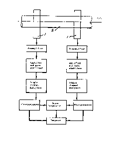
direction of the flow at each location. Figure 3
schematically shows the location of two assemblies 1 and
the signal processing equipment used in the apparatus.
As shown in Figure 3 the outputs of the scintillation
detectoxs are amplified by a preamplifier and an amplifier
and gain stabilizer. The signals are then analysed using
either two single channel analysers as shown or a
multichannel analyser so that the detected intensities at
the two gamma-ray energies can be separately measured.
The single channel analysers or multichannel analyser are
gated so that counts over short time intervals, for
example in the range 1 to 50 milliseconds, can be
measured. In some applications where there are small
changes in count rates during the counting interval the
:,
use of short counting intervals is not necessary, A
mlcroprocessor calculates the value of R according to
equation (5), corresponding to each selected time
interval. A cross correlator of known type is used to
: :
cross~correlate the calculated values of R from each
:
channel to determine the time delay in passage of the
~ ~ oil/water between the two gamma-ray beams. A computer
: ~ inputs signals from the cross correlator and each
microprocessor. The computer is used to calculate:
i~ ~ (i) the velocity of flow of the li~uid from the time
~ : ~
~ delay and the known distance between the two
gamma-ray beams;
(ii) the mean volumes of oil, water and gas over the
cross section of the pipe from the ratio of the
intensities of the two gamma-ray beams of different
energies as descri~ed above; and
(iii) the mass flow rate of each component from (i) and
(ii)
Figures 4 to 7 show alternate embodiments of the
apparatus to measure flow velocity and mass flowrate. The
same reference numerals have been used to identify similar
parts. Only the features of these emhodiments which
differ from that described above will be discussed in
detail.
Figure 4 shows a geometrical arrangement of a
scintillation detector 10, detector collimators or
shielding 11 and thermal insulation 13 which can be used
to replace that in Figures 1 and 2. The main advantage of
this alternative geometry is that it i5 more compact than
that in Fiqures l~and 2.
: :
Figure 5 shows the major features of a second
embodiment of an apparatus to measure flow velocity of the
liquid~component ln an oil/water/gas mixture. This
embodiment utilises a~number of dual energy gamma-ray
transmisslon assemblies, but with a common set of two
radioisotope sources 6, to scan different parts of the
pipe cross-section. This is necessary when the
oil/water/gas ml~ture~is heterogeneous over the
cross-section of the pipe. The gamma-ray beam is
.
- 20 -
~3~
relatively hroad over the cross-section of pipe shown, ~ut
is narrow along the length o the pipe as for the
arrangement in Figures 1 and 2. As shown five spaced
apart scintillation detectors 10 sspaIated by shielding 11
forming collimator systems are employed. B~ arrangin~ the
detectors and collimators around an arc and providinq
additional windows 5 gamma-rays from source 6 reach each
of the detectors 10. The operation of the Figure 5
embodiment is for practical purposes the same as for the
first embodiment save for the processing of several
channels of data. Thermal insulation, although not shown,
can be used to surround the detector and the collimator
systems.
Figure 6 shows the major features of a third
embodiment of an apparatus to measure flow velacity of the
liquid component in an oil/water/gas mixture. This
embodiment utilises a number of dual energy gamma-ray
transmission assemblies to scan different parts of the
pipe cross-section, necessary when the oil/water/gas
mi~ture is heterogeneous over the cross-section of pipe.
In this arrangement a number of gamma-ra~ sources 6 are
arranged in a linear array with shielding 7 forming a
number of parallel collimator systems. A similar linear
arrange of scintillation detectors 10 with shielding 11 is
provided on the opposite side of tube 2. This arrangement
allows a number of beams 9 to be transmitted through a
selected volume of the flow which includes substantially
the full cross-section of the tube. The operation of the
- 21 -
~3~
Figure 6 embodiment is for practical purposes the same asfor the first embodiment save for the processing of
several channels of data.
The processing system developed for use with
multiple detectors of the kind shown in Figures 4 to 6 can
accommodate up to 15 scintillation detectors under
computer control, giving values of R over time intervals
of down to one millisecond.
Figure 7 shows the major features of a fourth
embodiment of an apparatus to measure flow velocity of the
liquid component in an oil/water/gas mixture. This
embodiment has the dual energy gamma-ray assembly in the
form of a probe formed by the radioisotopes 6, source
collimation and shielding 7, the window 5, and pillars 14
which provide rigid support. The probe is immersed into
the main pipe stream of the oil, water and gas mi~ture.
This arrangement is used when pipe diameters are so large
that insufficient low energy gamma-rays penetrate the oil,
water and gas mixture and hence the detected intensity of
low energy gamma-rays cannot be measured accurately.
Although the foregoing describes the invention with
particular reference to a three phase oil~water/gas
mixture it is e~ually applicable to multiphase flows
comprising at least two liquid phases. Thus the invention
is also applicable to a flow consisting of two liquid
phases or a gas and more than to immiscible liquid phases.
~: :
- 22 -
:~:
,: .