Sélection de la langue

Search

Sommaire du brevet 1305603 

Énoncé de désistement de responsabilité concernant l'information provenant de tiers

Une partie des informations de ce site Web a été fournie par des sources externes. Le gouvernement du Canada n'assume aucune responsabilité concernant la précision, l'actualité ou la fiabilité des informations fournies par les sources externes. Les utilisateurs qui désirent employer cette information devraient consulter directement la source des informations. Le contenu fourni par les sources externes n'est pas assujetti aux exigences sur les langues officielles, la protection des renseignements personnels et l'accessibilité.

Disponibilité de l'Abrégé et des Revendications

L'apparition de différences dans le texte et l'image des Revendications et de l'Abrégé dépend du moment auquel le document est publié. Les textes des Revendications et de l'Abrégé sont affichés :

  • lorsque la demande peut être examinée par le public;
  • lorsque le brevet est émis (délivrance).
(12) Brevet: (11) CA 1305603
(21) Numéro de la demande: 1305603
(54) Titre français: PROCEDE D'ENTRELACEMENT DE FILS, A GUIDE CRANTE
(54) Titre anglais: NOTCHED GUIDE FILAMENT YARN INTERLACER
Statut: Durée expirée - après l'octroi
Données bibliographiques
(51) Classification internationale des brevets (CIB):
  • D02J 1/08 (2006.01)
(72) Inventeurs :
  • COONS, ANDREW MONROE, III (Etats-Unis d'Amérique)
(73) Titulaires :
  • HONEYWELL INTERNATIONAL INC.
(71) Demandeurs :
  • HONEYWELL INTERNATIONAL INC. (Etats-Unis d'Amérique)
(74) Agent: GOWLING WLG (CANADA) LLP
(74) Co-agent:
(45) Délivré: 1992-07-28
(22) Date de dépôt: 1989-05-25
Licence disponible: S.O.
Cédé au domaine public: S.O.
(25) Langue des documents déposés: Anglais

Traité de coopération en matière de brevets (PCT): Non

(30) Données de priorité de la demande:
Numéro de la demande Pays / territoire Date
220,042 (Etats-Unis d'Amérique) 1988-07-15

Abrégés

Abrégé anglais


ABSTRACT OF THE INVENTION
Disclosed is a fluid jet interlacing device for
commingling yarns. The interlacing device features notches in the
inlet and exit orifices which provide for better wear resistance
and evenness between related devices.

Revendications

Note : Les revendications sont présentées dans la langue officielle dans laquelle elles ont été soumises.


The embodiments of the invention in which an
exclusive property or privilege is claimed are defined as
follows:
1. An apparatus for entangling filaments of one or more ends of
synthetic yarn comprising:
(a) a housing;
(b) a longitudinal cylindrical bore through said housing
for the passage of said yarn therethrough, said bore
having an inlet and an exit opening in said housing;
(c) a fluid passage through said housing intersecting
the yarn passage bore;
(d) a slot or notch in the cylindrical bore at each inlet
and exit opening.
2. The filament entangling apparatus of Claim 1 wherein the
inlet and exit slot or notch have a radial curvature.
3. The filament entangling apparatus of Claim 2 wherein the sides
of the slot or notch are straight.
4. The filament entangling apparatus of Claim 2 wherein the sides
of the slot or notch are angled or curved.
5. The filament entangling device of Claim 1, wherein said slot
or notch comprises a straight notch of substantially 45°.
6. The filament entangling device of Claim 5 wherein said 45
notch has angled sides, the angle between the sides being about
90°.
-7-

Description

Note : Les descriptions sont présentées dans la langue officielle dans laquelle elles ont été soumises.

~3~5~03
C-10316
BACRGROUND oF THE INVENTI~N
Jet interlacers of natural and synthetic fi~ers are
known.In U.S. Letters patent 2,884,756, for example, there is
di~c10s2d an apparatus and process for produciny a bulked yarn,
wherei~ ~ smooth or flat yarn is drawn in from the side (see
Figure 3 therein) into an aspirator-type device. The yarn is
withdra-~n from the device at a lesser speed, whereby the action of
fluid within the aspirator ~one causes the individual fila~ents of
the yarn therein to form small loops and the ~ila~ents bind among
the~selves. As noted at column 3, tha yarn is withdrawn from the
device at an abrupt angle. The device in U.S. Letters Patont
2,997,771 is simllar in desi~n and operation, but has an even
greater flared exit orlfice. See a~lso U.S. Letters Patent
3,103,731.
U.S. Letters Patent 3,026,59? is an example of an
interlacingftsxturing iet in which the fluid for interlacingf
texturing enters from on~ side of th2 yarn conduit. In this
device, the yarn co~duit or passage i~ tapered uniformly from the
inlet end to its exit. The fluid passage com~unicates with the
yarn passage about midway through thc d~vice. See also U.S.
Letters Patent 3,665,566 for another example of side entry fluid
lnlets.
--1--

~339~ 3
U.S. Letters Patent 3,574,24g dQscribes a yarn
threadline treating apparatu~ including 1 series o~ guides for the
threadline associated with a ~luid withdrawal enclosure. U.S.
L~tters P~t6nt 4,188,6~2 descri~a~ an air jet device having
alternate inlets to the yarn passageway and an angled air inlet.
V.S, Letters Patent 3,846,968 and 4,223,520 are typical
of the use of such devices as air jets to entangle ~ultiple ends
o~ synthetic fila~ents. U.S. Letters Patent 4,318,21C reflects
the use of a hot air device for hot drawing yarn drawn at an angle
over pin~ 12. Finally, U.S. Letters Paten_ 4,570,31~ describes a
method and process for air entangling a plurality of yarn ends.
It is a characteristic of these d~vices, regardless of
the materials of ~onstruction, to u:Lti~ately wear due to continual
passage o~ yarns through the device under varying amounts of
frictional forc~s. In the somewhat random nature of contacting
the yarn filaments with the jet sur~ace, wear from device to
device is uneven, and much care and exercise ~ust be taken to
prev~nt thQ inconsistencles in wear ~ro~ being translated into
inconsis~encies in the entan~led product being ~ade.
This is especiaily true for jet~ in which yarn is fed
thereto in angled relationship to the yarn passage. The tensions
created in ~ragging the yarn through tbe jet entrance lowers the
entangling performan~e of the jet.

~3~S603
The improve~ant of this lnvention i.n such devices
comprises the addition of a means for eli~inating or subst~ntially
reducing tha variations in consistcncy fro~ position to position.
S The means provides for greater uni~or~ity ln tension or drag
levels through the air ~et de~ice. Furthermore, the ~eans serves
as an aid for guiding yarns into th~ yarn passaseway of the jet.
It serves to increa~e th~ life expectancy of the air jet by
mini~ zing tension drag variations over a longer period than
t0 d~vices heretofore known.
The invention co~prises placement of a small notch or
slot in the entrance and exit sections of the yarn passage in the
area where the yarn will contact the jet. ~ore detailed
desc~iptions o~ the invention ~ay ~e seen in reference to the
draw~ngs in which:
BRIEF DESCRIPTION OP THE DRAWINGS
Figure l represents an end view of an air jet of the
design o~ the invention:
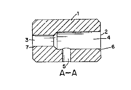
i Figure 2 represents a seGtlonal view of the air jet in
Figure l along reference line A-A:
Figure 3 i9 an enlarged sectional view of a rounded slot
e~bodiment;
Figure 4 represents an end view of a fluid jet design
lncorporating another erbodi~ent of the invention; and
.

~S~3
F$qure 5 and Figure 6 ~how details of the notch
e~bodi~ent of FigNrc 4.
pETAILED DESCRIPTION OF THE DRAWINGS
Figur~ 1 depicts a conventional air jet housinq 1 ha~inq
a yarn passageway 2 comprising two concentric cylindrical bores 3
and 4 of different diameters and end to end. An air inlet 5 tSee
Figure 2) intersects the larger cylindrical passage bore 4
perpendicular to the yarn passage. Yarn threaded through the
passageway normally enters the larger bore 4. Air or other fluid
~rom a supply not shown enters the yarn passageway in a manner
similar to that disclosed in the ref~rences cited herein.
At th~ yarn contact point of each end, a slot 6 and slot
7 shown in enlarged detail in Figure 3, slots 6 and 7 in this
embodiment are formed with a radial ~:~rvature. The site 8 o~ the
~lot i3 shown straight, but ~ay itself be curved or angled (se~,
e.g., Figore 6)~
The air jet body may be made from any conventional
material suitable ~or such devices. Type 316 stainless steel may,
for example, be the material oE construction. The details of th~
~et may be ~achined from bar stocX or cast. The jet housing may
also be ~ade fr~m a nu~ber oE ceramic materials, known or their
hardness and abrasion res$stance. In the latter instance, the
details may be molded into green or unfired units. The slots 6
and 7 ~ay b~ formed in the green state ~r cut before firing.

~3~
Th~ notch e~bodi~ent in Figure~ 4 to 6 compris~s a
straight notch 10 o~ substanti~lly 45- x 90-. This e~bodiment ls
more ea~ily formed in, ~or ~xample, a green cera~ic jet be~oro
~iring.
E~A~P~E 1
An air jet stoc~ is formed fro~ aluminum oxide cera~ic
material having the configuration shown in Figure 2. The housing
dia~eter is 3~4" and i9 1~ in length. ~he two yarn passage inner
diameters are 1/4" and 3/8~. ~ 1/8" air inlet is ~s shown in
Figure 2. ~owever, no notch is placed in the inlet and exit
sections of the yarn passag3.
A second air jet is constructed in tha same ~anner, but
notohes o~ 450 x 90 similar to that shown in Figures 4-6 are
formed ~n the green ~aterial prior to firing.
Two ~nd~ of 2,200 denier nylon yarn, each having 112
filaments, are passe~ through the first jet, with tile jet having
alr at 110 PSIG beinq fed to lt. The inlet tçnsion on tl~e varns
ls 75-125 g. rhe yarns are passed ~Irou~h the jet at 500 ypm.
The above test is repeated with t~e second jet ~notched)
2~ using the same conditions. The entangle~ent ~odes (se~ U.S.
Lstter~ Patent 4~223,520) with ~et 1 (no notch) averages 30/meter.
The entang~ement nodes of the yarns through jet 2 ~45 x 90-
notch) averages 35/meter. Surprisingly, a 17% increase in
~ntanglement ~ of node~ per ~eter) is obtained under the same
processing conditions through the use of tho 4S X 90 notches.
-

~30S~;03
An air jet body si~ilar to j~t 1 in Example 1 wasconstructed, but slots a~ in Figure 1 and 2 are added. IWO ends
of nylon yarn are passed through the jet under conditions set out
in Example 1. The entanglement of ~hese yarns avera~s 33
nodes/meter or an increase of 10% over jet 1 in Example 1.
The improvement in entanglement in Example~ 1 and ~ does
not reflect a more difficult to characterize improvement in
consistency and uniformity noted in carpets made from yarns passed
lo through the notched jets. Further, the increase in life expectan~y
and point t~ point unifor~ity of t~e notched jets has made this
significant improvement in the end product possible.
--6--

Dessin représentatif
Une figure unique qui représente un dessin illustrant l'invention.
États administratifs

2024-08-01 : Dans le cadre de la transition vers les Brevets de nouvelle génération (BNG), la base de données sur les brevets canadiens (BDBC) contient désormais un Historique d'événement plus détaillé, qui reproduit le Journal des événements de notre nouvelle solution interne.

Veuillez noter que les événements débutant par « Inactive : » se réfèrent à des événements qui ne sont plus utilisés dans notre nouvelle solution interne.

Pour une meilleure compréhension de l'état de la demande ou brevet qui figure sur cette page, la rubrique Mise en garde , et les descriptions de Brevet , Historique d'événement , Taxes périodiques et Historique des paiements devraient être consultées.

Historique d'événement

Description Date
Inactive : Périmé (brevet sous l'ancienne loi) date de péremption possible la plus tardive 2009-07-28
Lettre envoyée 2005-08-23
Lettre envoyée 2001-08-08
Accordé par délivrance 1992-07-28

Historique d'abandonnement

Il n'y a pas d'historique d'abandonnement

Titulaires au dossier

Les titulaires actuels et antérieures au dossier sont affichés en ordre alphabétique.

Titulaires actuels au dossier
HONEYWELL INTERNATIONAL INC.
Titulaires antérieures au dossier
ANDREW MONROE, III COONS
Les propriétaires antérieurs qui ne figurent pas dans la liste des « Propriétaires au dossier » apparaîtront dans d'autres documents au dossier.
Documents

Pour visionner les fichiers sélectionnés, entrer le code reCAPTCHA :


Pour visualiser une image, cliquer sur un lien dans la colonne description du document. Pour télécharger l'image (les images), cliquer l'une ou plusieurs cases à cocher dans la première colonne et ensuite cliquer sur le bouton "Télécharger sélection en format PDF (archive Zip)" ou le bouton "Télécharger sélection (en un fichier PDF fusionné)".

Liste des documents de brevet publiés et non publiés sur la BDBC .

Si vous avez des difficultés à accéder au contenu, veuillez communiquer avec le Centre de services à la clientèle au 1-866-997-1936, ou envoyer un courriel au Centre de service à la clientèle de l'OPIC.


Description du
Document 
Date
(aaaa-mm-jj) 
Nombre de pages   Taille de l'image (Ko) 
Page couverture 1993-11-04 1 12
Abrégé 1993-11-04 1 8
Dessins 1993-11-04 1 24
Revendications 1993-11-04 1 24
Description 1993-11-04 6 156
Dessin représentatif 2002-02-01 1 7
Correspondance 2001-08-08 1 29
Taxes 1996-06-18 1 43
Taxes 1995-06-10 1 38
Taxes 1994-06-10 1 46