Sélection de la langue

Search

Sommaire du brevet 1305748 

Énoncé de désistement de responsabilité concernant l'information provenant de tiers

Une partie des informations de ce site Web a été fournie par des sources externes. Le gouvernement du Canada n'assume aucune responsabilité concernant la précision, l'actualité ou la fiabilité des informations fournies par les sources externes. Les utilisateurs qui désirent employer cette information devraient consulter directement la source des informations. Le contenu fourni par les sources externes n'est pas assujetti aux exigences sur les langues officielles, la protection des renseignements personnels et l'accessibilité.

Disponibilité de l'Abrégé et des Revendications

L'apparition de différences dans le texte et l'image des Revendications et de l'Abrégé dépend du moment auquel le document est publié. Les textes des Revendications et de l'Abrégé sont affichés :

  • lorsque la demande peut être examinée par le public;
  • lorsque le brevet est émis (délivrance).
(12) Brevet: (11) CA 1305748
(21) Numéro de la demande: 1305748
(54) Titre français: CORDON SURMOULE POUR CHAUFFE-MOTEUR
(54) Titre anglais: CORD SET FOR BLOCK HEATERS
Statut: Périmé et au-delà du délai pour l’annulation
Données bibliographiques
(51) Classification internationale des brevets (CIB):
  • H01R 13/627 (2006.01)
  • H01R 13/64 (2006.01)
(72) Inventeurs :
  • WERNICKE, WALTER (Canada)
  • PETERSEN, ARTHUR (Canada)
(73) Titulaires :
  • PHILLIPS & TEMRO INDUSTRIES LTD.
(71) Demandeurs :
  • PHILLIPS & TEMRO INDUSTRIES LTD. (Canada)
(74) Agent: ADE & COMPANY
(74) Co-agent:
(45) Délivré: 1992-07-28
(22) Date de dépôt: 1988-02-18
Licence disponible: S.O.
Cédé au domaine public: S.O.
(25) Langue des documents déposés: Anglais

Traité de coopération en matière de brevets (PCT): Non

(30) Données de priorité de la demande: S.O.

Abrégés

Abrégé anglais


- 11 -
ABSTRACT OF THE DISCLOSURE
An electrical cord set is used with an AC
operated automotive accessory, such as a block heater.
The cord set includes a multi-conductor electrical cord
having one end connected to the accessory or a connector
for electrical coupling to the accessory. At the other
end of the cord is the usual multi-prong electrical plug
for connection to a mains power outlet or the end of an
extension cord. To enable the cord set to pass through a
small dimension opening in an automotive grill, the cord
is provided with a disconnectable coupling between its
ends. The coupling includes mating male and female
parts, with the male part having a thin, plate-like shape
dimensioned to fit through a narrow slot in an automotive
grill. This avoids the necessary routing of the cable
either under the bumper of the vehicle or through the
joint between the hood and the surrounding vehicle body.

Revendications

Note : Les revendications sont présentées dans la langue officielle dans laquelle elles ont été soumises.


- 8 -
CLAIMS:
(1) An electrical cord for use with an AC
operated automotive accessory, comprising a multi-
conductor electrical cord having an accessory end fixed
to a part of substantially greater size than the cross-
sectional dimension of the cord, a plug end fixed to a
multiple contact electric plug also substantially greater
size than the cross-sectional dimension of the cord, and
a disconnectable cord coupling between the accessory and
the plug ends of the cord, having mating components
connected to respective parts of the cord, at least one
of said components having a thin profile with at least
one transverse dimension substantially less than the
minimum cross-sectional dimensions of the part and the
plus.
(2) A cord according to Claim 1 wherein the
plug is a three conductor male plug.
(3) A cord according to Claim 1 wherein the
part is an accessory plug for connection to the acces-
sory,
(4) A cord according to Claim 1 wherein the
cord coupling comprises a female component and a substan-
tially flat male component engageable therewith.
(5) A cord according to Claim 4 wherein the

- 9 -
male component is a flat, plate-like block.
(6) A cord according to Claim 5 wherein the
male component has sockets in a free end thereof.
(7) A cord according to Claim 6 wherein the
female component is a block with a recess in one end for
receiving the free end of the male component.
(8) A cord according to Claim 7 wherein the
female component has pins in the recess for engagement in
the sockets of the male component.
(9) A cord according to Claim 5 wherein the
male component has a chamfered leading edge at the free
end.
(10) A cord according to Claim 9 wherein the
male component has a peripheral groove adjacent the lead-
ing edge.
(11) A cord according to Claim 10 wherein the
female component has an internal peripheral rib for
engagement in the peripheral groove of the male compon-
ent.
(12) A cord according to Claim 4 wherein the
male and female components are configured to allow
engagement of the two in one orientation only.
(13) A cord according to Claim 1, 2 or 3
wherein the accessory is a block heater.

- 10 -
(14) A cord according to Claim 4, 5, or 6
wherein the accessory is a block heater.
(15) A cord according to Claim 7, 8 or 9
wherein the accessory is a block heater.
(16) A cord according to Claim 10, 11 or 12
wherein the accessory is a block heater.

Description

Note : Les descriptions sont présentées dans la langue officielle dans laquelle elles ont été soumises.

~3~ 8
FIELD OF THE INVENTION
The present invention relates to automotive
accessories and more particularly to a cord for an auto-
mobile accessory operated by AC current through an exten-
sion cord.
BACKGROUND
Known automobile accessories operated by AC
power through extension cords include block heaters,
battery chargers, battery warmers and in-car heaters. In
most cases, such accessories have an electrical cord that
extends from the accessory to a three prong plug that is,
in use, plugged into an extension cord for connection in
turn to a conventional AC mains power outlet.
In the past, it has been conventional practice
to pass the cord of the accessory through the grill in
front o~ the automobile radiator so that the plug is
readily available. The cord may be tied or otherwise
connected to the grill to keep the plug in place. How-
ever, some automobile designs are such that the relative-
ly large plug cannot fit through the small openings
available in the automobile grill. This makes it diffi-
cult to pass the cord to the front of the automobile in a
protected and relatively secure position. In these

i7~
cases, practice has been either to drop the cord out of
the engine compartment and pass it under the vehicle
bumper to hook on to the front of the vehicle, or to pass
the cord between the hood and the surrounding body
panels. Neither arrangement is particularly satisfac-
tory. If a cord running under the bumper should come
loose, the plug and cord will drag on the ground and will
become dirty, difficult to extract from under the car and
likely damaged. Passing the cord through the joint
between the hood and the surrounding body of the vehicle
leads to jamming, possible damage to the vehicle and
cutting of the cord.
The ob]ective of the present invention is to
provide a cord set that ameliorates this problem.
SUMMARY
According to the present invention there is
provided an electrical cord for use with an AC operated
automotive accessory, comprising a multi-conductor elec-
trical cord having an accessory end ~ixed to a part of
substantially greater size than the cross-sectional
dimension of the cord, a plug end fixed to a multiple
contact electric plug also substantially greater size
than the cross-sectional dimension of the cord, and a
'~

13~5~
disconnectable cord coupling between the accessory and
the plug ends of the cord, havi:ng mating components
connected to respective parts of the cord, at least one
of said components having a thin E~rofile with at least
one transverse dimension substantially less than the
minimum cross-sectional dimensions of the part and the
plug.
The thin component of the cord coupling is
~esigned to pass through narrow openings in a vehicle
grill so that one part of the cord can be installed in
the engine compartment and the other outside, with the
thin part of the coupling threaded through the grill for
connection to the other part of the coupling.
BRIEF DESCRIPTION OF THE DRAWINGS
In the accompanying drawings, which illustrate
an exemplary embodiment of the present invention:
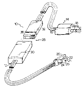
Pigure 1 is a pictorial representation of a
cord set according to the present invention for use in
conjunction with a block heater;
Figure 2 is a plan view of the thin component
of the cord coupling;
Pigure 3 is a side elevation of the thin c~m-
ponent of the cord coupling; and
Figure 4 is a plan view, partially broken away,
"

~3~
showing the internal configuration of the two components
of the cord coupling.
DETAILED DESCRIPTION
Referring to the accompanying drawings, ther~
is illustrated a cord set 10 for an automotive block
heater. The cord set has a three wire electrical cord 12
with a plug 14 fitted to one end. The plug consists of a
molded block 16 with two blades 17 and a round ground
prong 18 projecting from its end. This type of plug is
conventional in form and is used to engage a grounded
mains power outlet of the conventional type.
At the other end of the cord 12 is a molded
block 20 that includes an arcuate lug 22 projecting from
one of its side faces. The lug has two sockets 24 for
connection to contact pins of an automotive block heater,
and a ground socket 26 for connection to a ground contact
of the heater. Between the plug 14 and the heater con-
nection 20, there is a cord coupllng 28 that has a female
part 30 and a male part 32. The male part is thin, flat
:
and of ~enerally rectangular outline as illustrated in
Figures 2 and 3. The dimensions are such that this part
can flt through the small openings in an automotive
grlll. The leading edge 34 of the male part 32 is cham-

~3~ 8
-- 5 --
fered and a peripheral groove 36 is provided spacedslightly from the chamfered edge.
The female part 30 of the coupling 28 is also
of flat, rectangular form, although it is larger in
dimension than the male part. As illustrated most parti-
cularly in Figure 4, there is a socket 38 in its end face
that is dimensioned to receive the end of the male part
32. There is a peripheral rib 40 around the inner lip of
the socket 38 to engage the groove 36 in the male part,
when it is seated in the socket 38. During the engagement
process, the wall of the female part around the socket 38
stretches over the end of the male part until the rib 40
contracts into the groove 36.
The female part 30 of the coupling 28 has three
prongs 42 spaced along the socket 38 and projecting from
it. These correspond to the ~hree wires of cord 12 an~
fit into matching sockets 44 in the end of the male part
32. The sockets 44 are lined with sleeves a6 that are
electrically connected to the three wires of the cord 12,
as are the prongs 42. As illustrated most particularly
in Figure 4, the prongs and the sockets are asymmetrical-
ly arranged 50 that the male and female parts can only be
coupled in one orientation.
To install the cord ~et 10 for use, the part of

13~1S7~1~
-- 6 --
the cord containing the heater plug 20 and the female
part 30 of the coupling 28 is installed in the engine
compartment of the vehicle, with the female part 30
located adjacent the grill through wh:ich the cord is to
exit the engine compartment. The cord may be fastened in
place with appropriate fasteners. The heater plug 20 is
engaged in the usual way with the engine block heater.
The remainder of the cord set is located outside of the
engine compartment and the male part 32 of coupling 28 is
threaded through an appropriate opening in the vehicle
grill. Because of the thin dimension of this part, it
can fit through much smaller spaces than either the plug
of 14 or the heater connection 20. The two parts of the
coupling 28 are then engaged with one another to provide
a complete cord set with one end connected to the block
heater and the other end available outside of the grill
of the automobile for connection to the usual extension
cord.
While the invention has been described in
connection with a block heater cord, it is to be under-
stood that it is equally appllcable to electrical cords
for other automotive accessories, such as battery
chargers, battery warmers, in-car heaters and the like.
With some accessories of this sort, the end of the cord

~L3~ 8
-- 7 --
opposite the plug 14 will be connected directly to the
accessory or to another component equivalent to the
heater connection 20 ~hat is too large to fit through
many automotive grill openings.
Thus, while the invention has been described in
one embodiment, it is to be understoud that the scope of
the invention is to be construed solely by reference to
the appended claims.

Dessin représentatif
Une figure unique qui représente un dessin illustrant l'invention.
États administratifs

2024-08-01 : Dans le cadre de la transition vers les Brevets de nouvelle génération (BNG), la base de données sur les brevets canadiens (BDBC) contient désormais un Historique d'événement plus détaillé, qui reproduit le Journal des événements de notre nouvelle solution interne.

Veuillez noter que les événements débutant par « Inactive : » se réfèrent à des événements qui ne sont plus utilisés dans notre nouvelle solution interne.

Pour une meilleure compréhension de l'état de la demande ou brevet qui figure sur cette page, la rubrique Mise en garde , et les descriptions de Brevet , Historique d'événement , Taxes périodiques et Historique des paiements devraient être consultées.

Historique d'événement

Description Date
Inactive : CIB désactivée 2011-07-26
Inactive : CIB de MCD 2006-03-11
Le délai pour l'annulation est expiré 2004-07-28
Inactive : Demande ad hoc documentée 2003-09-09
Lettre envoyée 2003-07-28
Inactive : Transferts multiples 1998-05-13
Lettre envoyée 1998-03-02
Accordé par délivrance 1992-07-28

Historique d'abandonnement

Il n'y a pas d'historique d'abandonnement

Historique des taxes

Type de taxes Anniversaire Échéance Date payée
Enregistrement d'un document 1996-01-25
TM (catégorie 1, 5e anniv.) - générale 1997-07-28 1997-07-10
TM (catégorie 1, 6e anniv.) - générale 1998-07-28 1998-07-08
TM (catégorie 1, 7e anniv.) - générale 1999-07-28 1999-07-02
TM (catégorie 1, 8e anniv.) - générale 2000-07-28 2000-07-04
TM (catégorie 1, 9e anniv.) - générale 2001-07-30 2001-07-03
TM (catégorie 1, 10e anniv.) - générale 2002-07-29 2002-06-18
Titulaires au dossier

Les titulaires actuels et antérieures au dossier sont affichés en ordre alphabétique.

Titulaires actuels au dossier
PHILLIPS & TEMRO INDUSTRIES LTD.
Titulaires antérieures au dossier
ARTHUR PETERSEN
WALTER WERNICKE
Les propriétaires antérieurs qui ne figurent pas dans la liste des « Propriétaires au dossier » apparaîtront dans d'autres documents au dossier.
Documents

Pour visionner les fichiers sélectionnés, entrer le code reCAPTCHA :


Pour visualiser une image, cliquer sur un lien dans la colonne description du document. Pour télécharger l'image (les images), cliquer l'une ou plusieurs cases à cocher dans la première colonne et ensuite cliquer sur le bouton "Télécharger sélection en format PDF (archive Zip)" ou le bouton "Télécharger sélection (en un fichier PDF fusionné)".

Liste des documents de brevet publiés et non publiés sur la BDBC .

Si vous avez des difficultés à accéder au contenu, veuillez communiquer avec le Centre de services à la clientèle au 1-866-997-1936, ou envoyer un courriel au Centre de service à la clientèle de l'OPIC.


Description du
Document 
Date
(aaaa-mm-jj) 
Nombre de pages   Taille de l'image (Ko) 
Dessins 1993-11-04 2 58
Abrégé 1993-11-04 1 25
Page couverture 1993-11-04 1 16
Revendications 1993-11-04 3 69
Description 1993-11-04 7 205
Dessin représentatif 2001-10-24 1 15
Courtoisie - Certificat d'enregistrement (document(s) connexe(s)) 1998-03-02 1 118
Avis concernant la taxe de maintien 2003-08-25 1 174
Correspondance 2003-08-25 3 166
Taxes 1995-06-21 1 62
Taxes 1996-06-18 1 44
Taxes 1994-04-26 1 33