Note : Les descriptions sont présentées dans la langue officielle dans laquelle elles ont été soumises.
13C)5924
VOLUME CONTROL CIRCUIT FOR USE IN
PORTABLE TELEPHONE OR THE LIKE
BACKGRO~ND OF THE INVENTION
The present invention relates to a volume control
circuit and, more particularly, to a volume control circuit
applicable to a portable vehicle-mounted telephone and
other equipment which are usable in any desired location.
A portable telephone, for example, is designed to be
usable inside and outside of a motor vehicle as desired
and, usually, provided with a volume control circuit to
facilitate communications at an optimal sound level with
no regard to the environment, i.e. both in the inside and
the outside of a motor vehicle. Specifically, the sound
level is raised while the telephone is used fixedly
positioned in a vehicle compartment (hereinafter referred
to an onboard condition), which suffers from much noise,
and lowered while it is carried by a person ou-tside of the
vehicle compartment (hereinafter referred to as a portable
condition). A drawback with a prior art volume control
circuit is that the sound level has to be adjusted every
time the condition under which the telephone is used is
changed as mentioned above. This adds to the labor
required for communication and, therefore, makes the
telephone inconvenient to use.
~ '
.
~` ~30~i9~
-- 2
SUMMAR~ OF THE INVENTION
It is, therefore, an object of the presen-t invention
to provide a volume control circuit which is convenient
to use.
It is another object of the present invention to
provide a volume control circuit which frees a person
from the need for adjusting sound level every time the
environment changes.
It is another object of the present invention to
provide a volume control circuit capable of automatically
controlling sound level depending upon the condition of
use of equipment in which the circuit is built.
It is another object of the present invention to
provide a vol,ume control circuit suitable for use with
a transportable type mobile telephone.
A volume control circuit of the present invention
~, includes amplifier means for amplifying an audio signal,
,`, and first and second holding means for holding the gain
of the amplifier means at a first and a second predetermined
value, respectively. Condition detector means produces
a condition detect signal by detecting a condition in
which equipment with the circuit is used. In response
~, to the detect signal,, switch means enables one of the
', first and second holding means, whereby sound level is
automatically controlled in matching relation to the
' condition of use of the equipment.
.'-:',
, . ~
. ' ~ ' .
~' ' ' ":
1305924
-- 3
BRIEF DESCRIPTION OF THE DRAWINGS
The above and other objects, features and advantages
of the present invention will become more apparent from
the following detailed description taken with the
accompanying drawinqs in which:
Fig. 1 is a schematic block diagram showing a portable
vehicle-mounted telephone to which the present invention
is applicable;
Fig. 2 is a schematic block diagram showing a volume
control circuit embodying the present invention;
Figs. 3A to 3C and 4A to 4C are views schematically
showing essential parts of the circuit of Flg. 2;
Fig. 5 is a schematic block diagram showing another
embodiment of the present invention;
Fig. 6 is a flowchart demonstrating the operation of
the circuit of Fig. 5;
Fig. 7 is a circuit diagram representative of a
specific cons~ruction of an electronic volume control circuit
which is included in the circuit of Fig. 5;
Figs. 8A and 8B are schematic views showing a specific
construction of a condition detector which is included in
the circuit of Fig. 5;
Fig. 9 is a diagra~ schematically showing a specific
construction of volume setting means which is also included
in the circuit of Fig. 5;
. .
' '
13059;~
-- 4
Fig. 10 is a flowchart demonstrating the operation of
a controller which is associated with the means of Fig. 9;
and
Fi~. 11 is a circuit diagram representative of back-
up means associated with a RAM (random access memory) ofFig. 5.
DETAILED DESCRIPTION OF THE INVENTION
Referring to Fig. 1 of the drawings, a portable
telephone, generally 10, may be selectively used in a fixed
position within a motor vehicle, or onboard condition, and
carried by a person outside of the motor vehicle, or
portable condition, as desired. The portable telephone 10
is communicatable with ordinary subscriber telephones and
other portable telephones via a base station (not shown),
which is connected to a public telephone network.
Voice entering a microphone 1~ is subject to frequency
modulation (FM) or the like, and frequency conversion into
a radio frequency at a transmitter 13. The output of
transmitter 13 is applied to an antenna 11 via an antenna
duplexer 12 to be transmitted to the base station. On -the
other hand, a signal from the base station which comes in
through the antenna 11 is routed to a receiver 16 by way
of the duplexer 12. The receiver 16 subjects the received
signal to frequency conversion and other processing, then
demodulates it to produce an audio signal, and then feeds
,
:
' '''''''''' .
~.3~)5~
~ 5 --
the audio signal to a speaker 18 via a volume control
circuit 17, which embodies the present invention. The
volume control circuit 17 serves to control the level of
the auaio signal automatically in matching relation to a
particular condition in which the telephone 10 is used,
as described in detail later. For example, the volume
control circuit 17 raises the sound level while the
telephone lO is in the onboard condition and lowers it
while it is in the portable condition, although it is
capable of controlling the sound level in the opposite
manner depending upon the ambient noise condition.
A controller 15 controls the transmission and reception
of various kinds of control signals from the base station~
tunes the transmitter 13 and receiver 16 to a desired
channel, while performing other various kinds of control.
In a second embodiment of the present invention which will
be described, the controller 15 may control the volume
control circuit 17 as schematically represented by a dotted
line.
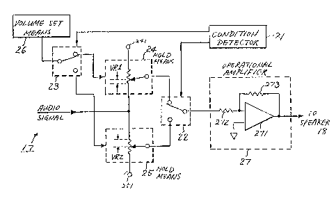
Referring to Fig. 2, the volume control circuit 17 in
accordance with the present invention is shown in a block
diagram. The audio signal from the receiver 16 (Fig. 1)
is fed to an operational amplifier (OP AMP) 27 via first
volume holding means 24 or second volume holding means 25
each of which comprises a variable resistor. The OP AMP 27
includes a differential amplifier 271, an input resistor 272,
~63 ~ 5 9~ ~
_
and a feedback resistor 273. The output of -the OP ~MP 27
is applied to the speaker 18 ~Fig. 1).
In response to an output of a condition detector 21,
a switch 22 determines whether to pass -the audio signal
through the first volume holding means 24 or to pass it
through the second volume holding means 25. The condition
detector 21 actuates~-the switch 22 depending upon the
condition of use of the telephone 10 (Fig. 1), i.e., the
onboard condition or the portable condition, as described
later. Further, the condition detector 21 controls a
switch 23 which is adapted to connect volume setting means
26 to either one of the first and second volume holding
means 24 and 25. The volume setting means 26, as stated
later, serves as means for changing the resistance values
~VRl and VR2) of the first and second volume holding means
24 and 25. One end 241 of the volume holding means 24 and
the end 251 of the volume holding means 25 are open-circuited.
When the telephone 10 is in the onboard condition,
the condition detector 21 controls the switches 23 and 22
to connect both the volume setting means 26 and OP AMP 27
to the first volume holding means 24. When the telephone
10 is in the portable condition, it controls the switches
23 and 22 to connect the means 26 and OP AMP 27 to the
second volume holding means 25. When the OP AMP 27 is
held in connection with the first volume holding means 24,
the input resistance of the amplifier 271 is the sum of
13~5~
-- 7 ~
the resistance of the resistor 272 and -the set resistance
(VRl) of the holding means 24. Similarly, when the OP
AMP 27 is in connection with the second volume holding
means 25, the input resistance of the amplifier 271 is
the sum of the resistance of the resistor 272 and the se-t
resistance VR2 of the holding means 25. Since the gain
of the amplifier 271 is dependent upon -the ratio between
the input resistance and the feedback resistance, the
amplification ratio of the audio signal is determined by
either one of the resistance values VRl and VR2 of the
holding means 24 and 25, respectively. This allows the
sound level or volume of the audio signal to be automatically
adjusted to suit a particular condition of use of the
telephone 10.
Referring to Figs. 3A to 3C, there are shown specific
cons~ructions of the switches 22 and 23, condition detector
21, and volume holding means 24 and 25. The conditions
shown in these figures hold when the telephone 10 is used
in the onboard condition. As shown, a knob 26 constitutes
the volume setting means and is held in toothed engagement
with the first volume holding means 24, so that the knob
26 may be rotated to rotate the holding means 24 so as to
change the set value of the holdiny means 24. The holding
means 24 is constituted by a resistance volume which per
se is well known in the art. When the telephone 10 is
fixed to a mount 30 of, for example, a motor vehicle as
13C~59;~4
-- 8 --
shown in Fig. 3B, the condition detector (plunger) 21 is
forced upward to in turn rotate the switch 23 about a
shaft 31 by leverage to the position shown in Fig. 3A.
At the same time, a metal plate or pattern 32 provided on
the plunger 21 and the switch 23 are brought into contact
with each other. The switch 23 is made of a conductive
material and connected to a power source line PS, so that
a control signal Sc to the switch 22 is maintained at
ground potential, thereby connecting the hold means 24
to the amplifier 27 as shown in Fig. 2.
When the telephone 10 is removed from the mount 30
as shown in Fig. 4B, the plunger 21 is forced downward by
the action of a leaf spring 29. As a result, the switch
23 is urged clockwise by a spring 28 until it becomes
fixed at the position of Fig. 4A. Simultaneously, the
switch 23 is moved away from the ground pattern 32 resulting
; with the control signal Sc being switched to a power source
voltage, e.g., +5 volts to actuate the switch 22, thereby
connecting the hold means 25 to the amplifier 27. Since
the knob 26 is connected to the second volume holding
means 25, the set value of the holding means 25 may be
changed.
Referring to Fig. 5, another embodiment of the present
invention is shown and made up of a CPU (central processing
25 unit) 51, an electronic volume 52, a condition detector 53,
volume setting means 54, and a RAM (random access memory) 55.
~30~;924
The CPU 51 may be constituted by the controller 15 of the
telephone 10 and implemented with, for example, ~uPD70008
manufactured and marketed by NEC Corporation. The
operation of the volume control circuit will now be
described with reference to Fig. 6.
When the telephone 10 is powered (Step Sl), whether
it is in the onboard condition or in the portable conditio
is determined based on an output signal of the condition
detector 53 (Step S2). If it is in the onboard condition,
the program advances to Step S3 for controlling the
electronic volume 52 to a particular value which is stored
in a first memory area of the RAM 55 and associated with
the onboard use of the telephone 10. When the telephone 10
is in the portable condition as decided in Step S2, the
flow advances to Step S4 so that the electronic volume 52
is controlled to another particular value which is stored
in a second memory area of the RAM 55 and associated with
the portable use. In this manner, a different optimal
sound level is set up for each of the onboard use and
portable use of the telephone 10.
A procedure which occurs in response to a change in
set sound level is as follows. When the volume setting
means 54 is operated (Step S5) to change a set sound level,
the CPU 51 determines whether the telephone 10 is in the
onboard condition or in the portable condition by referencing
the output signal of the condition detector 53 (Step S6)o
~L30592~
-- 10 --
If it is in the onboard condition, the program advances
to Step S7 for storing in the first memory area of the
RAM 55 a particular onboard value which is associated
with a change signal from the volume setting means 54,
whereby a sound level for onboard use is set. Step S7
is followed by Step S3.
When the telephone 10 is in the portable condition
as decided in Step S6, Step s8 is executed to store in
the second memory area of the RAM 55 a portable value
which is associated with the change signal. This sets
another particular sound level for portable use.
The Step S8 is followed by Step S4.
As shown in Fig. 11, the RAM 55 is backed up by a
super-capacitor 111 or the like so that it maintains the
values stored therein even if the power of the telephone 10
is turned off. In Fig. 11, the reference numeral 112
designates a diode which is connected to the power source
line for eliminating reverse~urrent flows.
Referring to Fig. 7, the electronic volume 52 is
schematically shown. An audio signal is amplified by a
first amplifier 65 to a predetermined level and, then,
applied to a resistance division circuit 66 to 70. A
first to a fourth switch 71 to 74 are so controlled as
to change the division ratio of the audio signal, the
resulting audio signal being applied to a second amplifier
75. Changing the division ratio of an audio signal causes
`` 1.30~924
-- 11 --
the sound level to change. The control over the switches
71 to 74 is effected hy the CPU 51 on the basis of set
values which are stored in the R~M 55. ~he outpu-t of -the
amplifier 75 is applied to the speaker 18.
Figs. 8A and 8B show a specific construction of the
condition detector 53. As shown, a reed switch 81 is
located adjacent to the outer periphery of a housiny 83
of the telephone 10 while a magnet 82 associated with the
reed switch 81 is provided on a mount 84 of a motor vehicle.
The reed switch 81 is connected at one end to a power
source voltage of +5 volts and the CPU 51 via a pull-up
resistor 85 and at the other end to ground. As shown in
Fig. 8A, when the telephone 10 is in the portable use,
the reed switch 81 is open so that the power source voltage
+5 volts is applied to the CPU 51 which, therefore, detects
the portable use of the telephone 10.
As shown in Fig. 8B, when the telephone 10 is in the
onboard condition, the reed switch 81 is closed to apply
ground potential to the CPU 51 allowing the CPU 51 to
detect the onboard use of the telephone 10.
Referring to Fig. 9, a specific construction of the
volurne setting means 54 is shown and constituted by a
push-type up-key 91 for raising the sound level and a
push-type down-key 92 for lowering it. The up-key 91 is
connected at one end to the CPU 51 and, via a pull-up
resistor 93, to the power source voltage (+5 volts) and
13059~4
- 12 -
at the other end to ground. Likewise, the down-key 92 is
connected at one end to the CPU 51 and, via a pull-up
resistor 94, to the power source voltage and at the other
end to ground.
When none of the up- and down-keys 91 and 92 are
pressed, the power source voltage is continuously applied
to the CPU 51. When any one of the keys 91 and 92 is
pressed, ground potential is applied to the CPU 51.
Detecting any of such voltages, the CPU 51 executes Step S5
(Fig. 6) for detecting the change in set sound level. More
specifically, as shown in Fig. 10, when the CPU 51 detects
the depression of the down-key 92, it decrements the set
value by 1 (one) and, then, advances to Step S6 (Fig. 6).
Upon detection of the depression of the up-key 91, the
CPU 51 incrernents the set value by 1 and, then, advances
to Step S6.
In summary, it will be seen that a volume control
circuit of the present invention is capable of changing
the sound level automatically in association with the
condition of use of a portable vehicle-mounted telephone
or like equipment, thereby promoting convenient use of
such equipment.