Note : Les descriptions sont présentées dans la langue officielle dans laquelle elles ont été soumises.
130621~
The present invention relates to e.g. an automatically
operated freezing plant comprising a plate freezer having a stack
of horizontal freezing plates and stepping means for subjecting
the ~tack to a succession of lifting steps each followed by a
smaller lowerlng step in such a manner as to successively place
each plate except the uppermost one at a charging and discharging
level. For each step, the respective upwardly next plate is
detained at a distance above the charging and discharging level
sufficient to permit the charging of freezinq goods from one side
of the stack into the enlarged interspace between the two plates
defining the charging and discharging level. At the same time,
simultaneous discharging of frozen goods from the interspace at
the other side of the stack occurs. Means are also provlded for
lowering the whole stack to lts original po~ltlon after freezing
and after frozen good~ have been charged into and discharged from
the lnterpace between the lowermost two plates. The plate freezer
1~ comblned wlth a plurality of identical plate freezers to form a
series of plate freezers in horizontally aligned arrangement with
the charging sides and discharging sides of the stacks situated ln
common planes.
It ls known to use a stepping arrangement as above
described in so-called manually operated horlzontal plate
freezers. In the operatlon of these, upon lowering of the stack
of plates to its origlnal positlon, a pre~sure is applled to the
stack, whereafter a freezing period is initiated during whlch the
;~ product i~ frozen followed by a thawing loose perlod, whereafter
the emptying and filling operations are repeated. Such manually
-- 2 --
.
1~06217
L
operated plate freezer has the advantage that since pressure is
applied to the product to be frozen during the freezing period, a
compact structure of the frozen material is achieved and, accord-
lngly, air pockets and uneven surfaces are avoided. However, such
plate freezer suffers from the drawback that the feeding of the
product to be frozen to the plate freezer and the removal of the
product must be carried out intermittently because the feeding of
the product to and the removal of the frozen product from the
plate freezer must be stopped during the freezing period and the
thawing loose period.
So-called automatic plate freezers of the kind referred
to whlch allow more or less continuous feeding of the product to
be frozen to the freezer and more or less continuous removal of
the product are di~clo~ed in GB 2,145,805, US 4,240,470 and US
; 4,553,406. In these known freezer~, cooling medlum is fed to the
plates all the time, and when an emptylng/fllling cycle has been
termlnated the whole stack i3 lowered, whereafter the emptying/
filling cycle ls repeated lmmedlately or wlth a mlnlmum delay.
During the freezing the product ls not sub~ected to other pres~ure
force~ than the pressure forces which the plates apply to each
other. The plate, whlch at any time forms "ceiling" above the
, ~
emptylng/free~ing interspace will be subjected to the pressure
~:,
from the plates positioned there above, and the plate whlch at any
tlme ls posltioned at the bottom of the stack will be sub~ected to
the pressure from the plates arranged there above incluslve the
plate which forms "floor" of the emptylng/fllllng interspace.
Accordlngly, the product positloned below the uppermost plate will
-- 3 --
~ . "
-` 130621t7
at the maximum be subjected to the pressure from this plate and
parts which may be connected thereto, if any. Furthermore, since
the plate freezer does not have any thawing loose period it may be
necessary to use violence upon the frozen product when this is to
be removed.
According to the present invention there is provided an
automatically operated freezing plant, comprising a plate freezer
comprising a stack of horizontal freezing plates, stepping means
for sub~ecting the stack to a succession of lifting steps each
followed by a smaller lowering step in such a manner as to
succeYsively place each plate except the uppermost one at a
charging and discharging level, while each time detaining the
respective upwardly next plate at a distance above the charging
and dlscharging levels sufficlent to permit the charging of freez-
lng good~ from one side of the stack into the enlarge interspace
between the two plates considered and the simultaneous discharging
of frozen goods from said inter~pace at the other slde of the
stack, and for lowering the whole stack to lts orlginal posltlon
after freezlng and after frozen goods have been charged into and
discharged from the interspace between the lowermost two plates,
characterized in that said plate freezer is combined with a
plurality of identlcal plate freezers to form a series of plate
freezers in horizontally aligned arrangement with the charging
sides and discharging sides of the ~tacks situatéd in common
planes, means being provided for automaticallyJ
applying a compressional force to each stack, after it has
~i been lowered to its original positlon, and concurrently
:1
l - 4 -
.~
. , .
. ~ .. , .; . .. . , .. .. .... - - .
.
~306;~7
initiating a supply of a freezing medium to each plate
of the stack;
maintaining the application of compressional force to the
stack and the supply of freezing medium to the plates
for a freezing period sufficient to freeze the goods in
position between successive plates;
: interrupting the supply of freezing medium to the plates and
~: substituting a supply of a thawing medium ~or a thawing
loose period sufficient to thaw the frozen goods loose
from the plates;
causlng said stepplng means to execute a full stepping period
finalized by lowerlng the stack to its original position
upon interrupting the application of compressional force
to the stack;
,. mutually timing recurrlng sequences of said perlods for the
; several stack~ in cyclical order in such a manner that
the stepping period of each stack is complsted during
;~ the freezing and thawing up periods of the re~aining
,'' stacks,
the number of stacks being equal to at least one plu5 the sum
:~ of the durations of a freezing period and a thawing
,~,
loose perlod of a stack dlvided by the duratlon of a
~; stepping period of a stack.
I~ is the object of the present invention to provlde a
freezing plant which may operate continuously without the draw-
backs connected with the abovementioned automatic plate freezer,
and which, accordingly, re~ult~ in the advantages which are
,:
- 4a -
.' ~
~ ' ,,~, " ''' ''''.. , :,.. .
- ' . - ~ ; .: '
1306217
achieved by means of the manually operated plate freezer, and this
object is accordlng to the invention achieved by constructing the
freezing plant according to the present invention described above.
~ereby lt i5 achleved that the freezing plant in question can
operate continuou#ly because one plate freezer may be emptied and
filled step by step while the other freezers freeze the product in
question and provide for thawing the product loose, but in such a
way that the next plate freezer is available for commencing its
first emptying and filling step immediately after the beforegoing
plate freezer has completed its last emptying and filling step.
Accordingly, lt is achieved that the series may be fed with the
product to be frozen in a continuous way and the product may also
continuously be removed from the ~eries and an excellent product
i~ achieved, because pressure is applled to the product durlng the
freezing perlod, and due to the thawlng loose period the with-
drawal of the frozen product causes no difficulties.
A freezing plant consisting of a series of vertical
plate freezers ls known from Prof. Dipl. Ing. Heinrich Drees,
"K~hlanlagen~, published 1972 by VEB Verlag Technik ~erlin, see
pages 273-274. In this known freezing plant the individual
vertical plate freezers are in turn subjected to a thawing medium
and emptied and then re-filled in a bath-wise operation under the
control of the operator. The known freezing plant therefore does
not allow for the establlshment of an uninterrupted smooth flow of
freezing and frozen goods through the freezing plant from an lnput
conveyor to an output conveyor wlthout human attendance.
- 4b -
~306217
The invention will hereinafter be further explained with
reference to the drawing, on which
Fig. 1 schematically shows a top view of an embodiment
of the freezing plant according to the invention,
Fig. 2 shows a side view of a plate freezer belonging to
the plant in Flg. 1, wherein, however, some parts have been
omitted for the sake of clarity,
Fig. 3 shows the plate freezer shown in Fig. 2 from the
left hand side of Fig. 2,
Fig. 4 shows a picture corresponding to Fig. 2 for
illustrating the
:
,,
,
- 4c -
: ~
~: . ' : , ' - ' .
,
-- 1306217
plate freezer during a first step during an emptying/filling opera-
tion, and
Fig. 5 shows a picture corresponding to Fig. 4 for illustrating a
final step after an emptying/filling cycle.
The freezing plant shown in Fig. 1 consists of four plate freezers
1, 2, 3 and 4 and a conveyor system which according to the
embodiment shown consists of a feeding conveyor 5 and a removing
conveyor 6. The plate freezers 1, 2, 3 and 4 constitute a series and
are according to the embodiment shown aligned with each other in
such a way that the feeding conveyor 5 and the removing conveyor 6
may serve all the plate freezers.
As it appears from Figs. 2-5 each plate freezer, e.g. the plate
freezer 1 on Fig. 1, comprises a stack of freezing plates 7 of which
seven are provided according to the embodiment schematically shown
on Figs. 1-5.
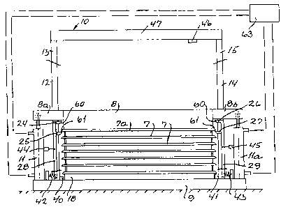
The uppermost freezing plate 7a is supported by means of a cross
beam 8 which at each end of the plate freezer has an outwardly
~ extending end 8a and 8b, respectively, and between each of the ends
; and a basis 9 for the frame 10 of the plate freezer a double acting
hydraulic cylinder 11 and 11a, respectively, is arranged.
The cylinders are arranged outside end frame parts each consisting
of two columns 12,13 and 14,15, respectively. Within each end frame
part 12,13 and 14,15, respectively, the corresponding end of the
cross beam 8 carries an end beam 15a extending crosswise with
;~ 30 respect to the cross beam, and of which only one is visible in Fig.
-~ 3. Each of these end beams is by means of bolts 16 and 17, connected
`~ with a supporting plate 18 for the lowermost freezing plate. The
upper ends of the bolts extend with clearance through a bracket 19
and 20, respectively, supported by the corresponding end beam 15a.
The upper ends of the bolts extend with a surplus length up over the
corresponding holes and a stop in the form of a nut 22 and 23,
respectively, is arranged at the upper end of each bolt.
At each end frame part two pawls 24,25 and 26,27, respectively, are
!
~306~17
arranged and each set of pawls is supported by a pawl arm 28 and 29,
respectively. The pawl arms are pivotally supported at their lower
ends with respect to the basis 9, and the bearing for the pawl arm
28 is shown in Fig. 3 and is designated 30. Accordingly, each pawl
arm 28 and 29 may make a small pivot movement as indicated by means
of the double arrow 32 in Fig. 4.
As it appears from Fig. 3 the plate freezer shown has a feeding
device 33 consisting of two horizontal arms of which only one 34 is
shown in Fig. 3. Each of the arms is supported by one of the columns
12 and 14, respectively. This feeding device has been omitted in
Figs. 2, 4 and 5 for the sake of clarity. Between the arms 34 a
pushing plate 35 is suspended by means of a pair of chains (not
shown) which by means of a motor 36 arranged above the pair of
chains may be moved to and fro as indicated by means of the double
arrow 37 in Fig. 3. The pushing plate 35 has a length which
generally corresponds to the length of the freezing plates 7. In
Fig. 3 the pushing plate 35 is shown in its outermost position,
wherein it is positioned above the edge of the feeding conveyor 5,
indicated by means of a broken line, facing away from the plate
freezer. Also the removing conveyor 6 is indicated by means of a
broken line, and accordingly it will be understood from Fig. 3 that
the two conveyors are arranged in the same level as the lowermost
pawls 25,27.
As indicated above each of the pawl arms 28 and 29 are pivotable in
the direction of the double arrow 32. Their pivoting in the inward
direction is limited by a stop 40 and 41, respectively, and moreover
each of the pawl arms are biased by a pressure spring 42 and 43,
respectively, which keep the pawl arms in the positions shown in
Fig. 2, but which permit the pawls 24,25 and 26,27, respectively, of
the pawl arms to pivot outwardly while compressing the springs in
; question and provided solenoides 44 and 45, respectively, which are
; arranged one between each of the cylinders 11,11a and the
corresponding pawl arm 28 and 29, respectively, are activated by the
activation of a contact 46 carried by the uppermost cross beam 47 of
the frame 10.
Each of the four plate freezers shown in Fig. 1 is provided with
1;~06217
manifolds 48,49; 50,51; 52,53 and 54,55, respectively, which by
means of conduits are connected with a distributor 56 arranged in
such a way that it can conduct cooling medium to the manifolds
49,51,53 and 55 and cause exit of cooling medium from the manifolds
48,50,52 and 54 in a controlled way. Moreover, the distributor 56
may conduct thawing up medium, e.g. hot gas to the manifolds
49,51,53 and 55 and provide exit for such thawing up medium via the
manifolds 48.50,52 and 54 also in a controlled way.
Each of the manifolds is connected with each of the plates of the
corresponding plate freezer for feeding said plates with cooling
medium/thawing loose medium and for removal of cooling medi-
um/thawing up medium. Such connections, preferably, are constituted
by flexible reinforced tubes which allow the movement of the
freezing plates.
The operation of the plant shown will be further explained below:
It is supposed that the plant shown in Fig. 1 is in operation and
that a freezing operation and a thawing loose operation have just
taken place as regards the plate freezer 1, and that the plates
thereof thereafter have been made inactive controlled by the
distributor 36. Now the hydraulic cylinders 11,11a of the plate
freezer in question are activated by means of a control system 63
schematicaliy shown in Fig. 2, whereby the cross beam 8 is lifted.
Thereby also the uppermost plate 7a is lifted, viz. corresponding to
the surplus lengths of the bolts 16,17. Thereafter the remaining
plates in the stack are lifted. When the uppermost plate 7a passes
- the pawls 24,26 the pawl arms 28 and 29 are pivoted outwardly by
cooperation between inclined surfaces 60,61 on the pawls and the
plate, respectively. After the passage the pawl arms pivot back to
the positions shown in Fig. 2. When the next plate passes the
lowermost pawls 25,27 the same operation occurs. The plate freezer
is provided with means (not shown) which when the two uppermost
plates have passed each set of pawls operate the control system 63,
-~ which now reverses the hydraulic cylinders 11,11a for lowering until
the two uppermost plates occupy the positions shown in Fig. 4. A
well defined interspace is now provided between the two plates and
this interspace is higher than the height of the interspace which
~ 7
~, . . .
~306217
the plates had during the freezing due to the surplus lengths of the
bolts 16,17 shown exaggerated in Fig. 3 for the sake of clarity.
Accordingly, it will be understood that this surplus movement does
not need to be considerably greater than the increase of the
interspace to be provided between the plates for emptying and
filling thereof. Now the feeding device 33 is activated whereby the
corresponding pushing plate 35 pushes a product, which in the
meantime has been fed by means of the feeding conveyor 5 and stopped
by means of the movable stop 65, Fig. 1, sideways into the
interspace provided between the two uppermost plates. This
pushing-in movement will simultaneously result in pushing at least a
part of the frozen product in the interspace in question out upon
the moving conveyor 6, because the two conveyors as previously
explained and as it appears from Fig. 3 are arranged exactly aligned
with the plate supported by means of the pawls 25 and 27. Now the
feeding device 33 by reversing the motor 36 moves the pushing plate
35 back to the position shown in Fig. 3, whereafter a new transfer
to the interspace of product which has been fed towards the stop 65
takes place These operations continue until the frozen product in
the interspace concerned has been transferred to the conveyor 6 and
product to be frozen has been inserted into the interspace in
question from the feeding conveyor 5.
Now the cylinders 11,11a are again activated and in the way
explained above the second plate from the top will now be brought to
rest upon the pawls 24 and 26, whereas the third plate from the top
will be brought to rest upon the pawls 25,27. Now a new
feeding/emptying interspace will be arranged opposite the conveyors
and filling and emptying of this interspace is now carried out in
the same way as previously explained. These operations continue
until the product in the whole stack has been exchanged. At the
final lifting step the contact 46 is activated whereby the two
solenoids 44 and 45 are activated whereby the pawl arms 28 and 29
are pivoted away from each other to the position shown in Fig. 5.
These movements simultaneously affect the control system 63 which
; reverses the cylinders 11,11a for lowering the whole stack until the
stack occupies the position shown in Fig. 2. After this position has
been reached the control system 63 will arrange for the applying of
a downwardly extending force upon the cross beam 8 by means of the
6217
cylinders, ll,lla and, accordingly, upon the plate stack ln such a
way that the product will be put under compression for driving
air, if any, out. Then the distributor 56 serves for feeding the
freezlng plates of the plate freezer in question with cooling
medium.
During at least the last part of the exchange cycle
explained above thawing loose is arranged for as regards the
product frozen in the plate freezer 2 controlled by means of the
distributor 56. Now the plate freezer 2 is refilled because the
stop 65 is lifted by means of the corresponding solenoid 65a, Fig.
3, and the product fed is now stopped by means of the second stop
66. The cycle explained above as regards the plate freezer 1 is
now repeated as regards the plate freezer 2 and in this way the
operatlon contlnues as regards the plate freezers 3 and 4, because
also these freezers are provided with movable stops 67 and 68,
re~pectively, ~orrespondlng to the stops 65 and 66.
The number of plate freezers belonqing to the line in
question ls equal to one plus the sum of the freezing period and
the thawing loose period of a plate freezer divided by the
inactive period of the plate freezer. Hereby it is achieved that
the plant in question can operate continuously, because one plate
freezer always undergoes an emptying/filling cycle while the other
operate for freezing and the next plate freezer to be subjected
the filling/emptying cycle undergoes the thawing loose step.
According to the example illustrated on the drawing four
plate freezers are provided. The freezing time plus the thawing
loose time according to the example shown for one of the plate
g
:
062~7
freezers is approximately one hour and an emptying/filling cycle
takes approxlmately twenty minutes.
It will be realized that in the drawing a series of
plate freezers is shown wherein the number of the plate freezers
i8 at a minimum. Howeverr it may be appropriate to provide the
serles with one or more further plate freezers in case of shifting
over to the freezing of another product or in order to be able to
operate the plant in case one or more of the plate freezers should
break down.
:~:
.
'
.
-- 10 --
: ~
-'- : . ; . - . .