Note : Les descriptions sont présentées dans la langue officielle dans laquelle elles ont été soumises.
~3~ 3'~
CAR(:.`O HANDLING SYSTEM
TEC~NI CAL FI ELD
This invention relates to material handlin~
system, such as ship loadin~ and unloadinq system and a
method for using the same. More particularly, this inven-
tion relates to a method and apparatus for loading and
unloading wherein the apparatus utilizes elevators intercon-
nected with a bridge structure and where the apparatus is
mounted on a quay and movable with respect thereto.
BACKGROUND ART
There are known various constructions of devices
for loading and unloading ships and other cargo carriers.
Exemplary of such devices is the reknown standard crane
which adorns ports worldwideO These cranes are mounted on
.; the quay of a port, or in some constructions to a mobile
base. The crane generally is provided with a hook which
i suitably is configured so as to engage cargo to be loaded
il 20 to, or unloaded from, a ship moored to the quay. To load,
; the crane hook engages cargo resting upon the quay and is
then moved vertically and horizontally toward the moored
ship~ The cargo is then deposited at a desired location on
! the ship and precisely located through independent means.
Unloading proceeds via a similar process.
This typical construction suffers from a variety
of problems. First, inasmuch as the crane hook cannot
handle cargo during its return time from the ship back to
the quay during loading, efficiency of the process is low.
Second, the utilization of independent means, especially
during unloading as required on the quay to remove deposited
cargo, mandates coordination between handlers which is often
difficult to obtain. In the case where the removal of cargo
from the quay fails to coincide with the unloading cycle of
the crane, either a pile up or extensive "dead time" is
experienced.
Others have attempted to obviate some or all of
these ~roblems. One early cons~ruction is the cargo
i
~.~3`n6~3~
handlin~ apparatus of U.S. Pat. No. 1,525,950, to Prescott.
The apparatus disclosed therein comprises a bridge, a
cantilever arm, a ship leg and a pier leg. The leg members
and arm utilize continuous conveyors for conveying the cargo
remote from the apparatus. The conveyors comprise trays
having concave-grid arm bottoms which move circuitously
throughout the entire apparatus.
U.S. Patent No. 3,952,891, to Terayama et al.,
and 4,172,685, to Nabeshima et al., provide methods of
improved handling of cargo with use of container cranes.
U.S. Pat. No. 4,175,908, to Andersson, discloses
an apparatus and method of loading and unloading heavy
objects. The complex apparatus disclosed therein provides
an alternative to harbor cranes or pontoon cranes.
According to the method a heavy object is lifted from the
quay, or a vehicle driveable along the quay, moved along
girders to a position above the hold of a ship, and then
lowered into the hold of the ship. While providing a viable
method of loading heavy objects, the method suffers from
inefficiency and other problems discussed hereinabove.
.S. Pat. No. ~,293,077, to Makino, is directed
to a container handling apparatus which provides an improve-
ment of an existing crane. The apparatus comprises a
~ traveling portal frame having a container transfer space and
¦ 25 an elevating device. A truck is also provided as a con-
tainer transport vehicle. In operation, the portal frame is
moved along the quay to a desired position. While providing
mobility, such action limits the usefulness of that portion
of the quay which must be reserved for this frame movement.
It should be evident, while the art has provided
ameliorations of harbor crane structures, a truly efficient
method and apparatus for loading and unloading of ships has
not heretofore been known. A further problem in the loading
and unloading of ships is encountered when the cargo being
handled may not be exposed to the elements. For example,
unloading of paper goods in rainy weather may not be accom-
plished without ùestruction of at least some of the carqo.
a ~r~
In this reqard, the aforesaid ~.S. Pat. No.
1,525,950, discloses the use of a support means/shield means
which is fitted over the hold of the ship. The cargo is
not, however, protected from the elements as it is unloaded
from the ship to the quay.
Russian Patent No. 796,130 discloses the use of a
flexible shield means which is fitted over the hatch of a
ship and is interconnected to an enclosed container handler.
The shield means however is not capable of being adapted to
different sized hatches or hatches at different angles due
to the mooring of the ship.
DISCLOSURE OF THE. INVENTION
It is therefore a primary object of the present
invention to provide a truly efficient material handling
system for use in the loading and unloading of ships.
It is another object of the present invention to
provide a material handling system, as above, wherein large
scale jobs and large objects may be unloaded or loaded with
~o relative ease.
It is a further object of the present invention
to provide a material handling system, as above, which is
movably affixed to the quay of the port and angularly
adjustable with respect to vessels moored to the quay
It is a still further object of the present inven-
tion to provide a material handling system, as above, which
enables loading or unloading of cargo which can be protected
from the elements of the weather throughout the process.
It is yet another object of the present invention
to provide a material handling system, as above, wherein
cargo can be easily removed from within the ship through the
hatch.
These and other objects of the present invention,
as well as the advantages thereof over existing and prior
art forms, which will be apparent in view of the following
specification, are accomplished by means hereinafter
described and claimed.
:~3~
--4--
In general, a system ~or transporting cargo
between a storaqe area and a cargo carrier includes a bridge
structure spanning bet~leen the storage area and the cargo
carrier. A first elevator is located at one end of the
bridge structure proximate to the storaae area. A second
elevator is located at the other end of the bridge structure
positionable relative to the cargo carrier. A trackway
extends along the bridge structure interconnecting the first
and second elevators. Independent cars are also provided
for carrying the cargo. The cars are movable on the first
and second elevators, and also along the trackway.
One preferred, exemplary embodiment of a cargo
handling system incorporating the concept of the present
invention is shown by way of example in the accompanying
drawings without attempting to show all the various forms
and modifications in which the invention might be embodied,
the invention being measured by the appended claims and not
by the details of the specification.
BRIEF DESCRIPTION OF THE DR~INGS
Fig. 1 is an elevational schematic view of a
cargo handling system embodying the concept of the present
invention.
Fig. 2 is a top plan schematic view of the cargo
handling system of Fig. 1.
Fig. 3 is an enlarged fragmentary plan view of the
articulated member of the bridge of the cargo handling
system taken substantially along line 3-3 of Fig. 1.
Fig. 4 is a fragmentary perspective view of the
shipboard loading station and hoist platform of the cargo
handling system of Fig. 1.
Fig. 5 is a frag~entary view of the hatch
cover and boom structure; and
Fig. 6 is a top plan view, par-tially in cross-
section, of a transport car of the cargo handling system
of Fig. 1.
~3~ 3~7
--5--
EXEMPLARY EMBODIMEI`~T FOR CARRYING OllT THE INVENTION
-
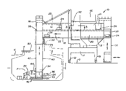
A cargo handling system, according to the concept
of the present invention, is indicated generally by the
numeral 10 in Fig. 1 of the accompanying drawings. Such a
cargo handling system 10 is positioned on a quay (Q) to
facilitate loading and unloading a cargo shipping vessel
(V). The cargo handling system 10 basically includes a
portal frame 11 which can travel along the quay (Q) using
suitable travel drives 12, known in the art. A fixed bridge
structure 13 is carried on portal frame 11. On the dock
side of fixed bridge structure 13 is located a dockside
elevator 14 as will be discussed more fully hereinbelow.
At the opposite side of the fi~ed bridge structure
13 is a rotating boom structure 15. As will be appreciated
hereinbelow, rotating boom structure 15 constitutes an
operable extension of fixed bridge structure 13 for purposes
of handling the cargo. ~ shipside elevator 16 is mounted
at the distal end of boom structure 15 for movement there-
with
Before discussing the details of the present
invention, it will be beneficial to appreciate certain
features of the structure heretofore described. The cargo
handliny system 10 is suitable for selective positioning
relative to the vessel (V) with which it is being used; and
more specifically it is positionable with respect to the
particular holds of the vessel ~V). The mobility of the
cargo handling system 10 is derived from travel drives 12
which enable the cargo handling system 10 to be positioned
along the quay (Q) and by rotating boom structure 15 which
swings outward from the quay (Q) to position shipside
elevator 16 relative to a hatch opening (H) of the vessel
(V) as depicted in Fig. 2.
Specifically with reference to Fig. 2, the cargo
handling system 10 is depicted with boom structure 15 in its
stored position (I), shown in solid lines. Such a position
permits cargo vessels to be docked and moored alongside the
quay (Q) free of any obstruction by the cargo handling
3~
system 10. When a cargo vessel has been properly moored,
boom structure 15 may be swung outward ~rom its stored
position (I) to a partially extended position (II) or a
fully extended position (III), eac~ depicted in broken lines
in Fig. 2, as necessary to align shipside elevator 16 over
a desired hatch opening.
Another aspect of the cargo handling system 10
which should be appreciated is the fact that it provides
protection to the cargo against weather. In order to
provide such protection, the respective cargo passageways of
bridge structure 13, dockside elevator 14, boom structure 15
and shipside elevator 16 all are enclosed with protective
material. Such material is well known in the art and may
include structural metal, or similar building material.
Turning now to the specific structure of the
invention, fixed bridge structure 13 houses a pair of track-
ways, designated as lower bridge trackway 20 and upper
bridge trackway 21. These trackways, 20 and 21, communicate
at one end with dockside elevator 14 and at the other end
with correspondina lower boom trackway 22 and upper boom
trackway 23, respectively, housed within boom structure 15.
As will be appreciated hereinbelow, the foregoing network of
trackways constitute a portion of the material handling
passageways of the cargo handling system 10, and are
suitably configured to permit travel o~ cargo cars 24 there-
through.
Inasmuch as lower trackways, 20 and 22, respec-
tively, are substantially identical to upper trackways, 21
and 23, respectively, discussion will be directed to the
latter, with reference being made to Fig. 3. Specifically,
each trackway 21 and 23 includes a guide rail, 25 and 26,
respectively, to guide cargo cars 24, as will be more fully
discussed hereinhelow. A rotatable platform 30 interfaces
between bridge trackway 21 and boom trackway 23 and includes
a platform rail 31. Rotatable platform 30 serves to accept
a cargo car 24 for one trackway, for example bridge trackway
21, and then align it with the other trackway, boom trackway
~6~t7
23, so as to permit cargo car 24 to contin~e onward, as will
be discussed hereinhelow. Rotatable platform 30 is partic-
ularly useful whenever boom structure 15 is not ali~ned with
bridqe structure 13. Flexible wall members 32 serve to
enclose rotating plat~or~ 30 to facilitate weatherproofing.
The nature of wall members 32 permit substantially unre-
stricted movement of boom structure 15 relative to bridge
structure 13.
Dockside elevator 14 provides a means for moving
cargo cars 24 between the brid~e structure 13 and the quay
level (Q) as depicted in Fig. 1. Specifically, a carrier
33 travels within dockside elevator 14 carrying cargo cars
24 between either lower bridge trackway 20 or upper bridge
trackway 21 and the quay (0). Suitable sensors and con-
trollers, known in the art, are provided to stop carrier 33at the appropriate locations ~o receive or discharge cargo
cars 24.
Similarly, shipside elevator 16 provides a means
in the form of a carrier 34 for moving cargo cars 24 between
rotatin~ boom structure 15 and the cargo hold of the vessel
tV). Unlike dockside elevator 14, the housing 35 of ship-
side elevator 16 does not extend down to the lowermost
limit of travel of carrier 34. Rather, housing 35 termin-
ates above the uppermost deck of the vessel (V). The lower~
most travel of carrier 34 is defined by a work station 36
which may be lowered from housing 35 into the cargo hold of
the vessel (V).
With reference to Fig. 4, work station 36 is
lowered, and supported by, suitable cables or ropes 40.
These may be affixed to the four lower corners of work
station 36 and operatively connected to suitable winches to
raise and lower work station 3~ as desired. Work station 36
preferably has a cubical frarnework 41 with a pair of
foldable platforms 42 and 43, respectively, mounted on
opposite sides thereof. Platforms 42 and 43 are suitably
configured to support cargo cars 24 when extended, and to
fold upright into framework 41 to provide a compact assemb]y
~3~3~
--8--
while work station 36 is maneuvered through a hatch opening
(~1). Once work station 36 is positioned within the cargo
hold of the vessel (V), work platforms 42 and 43 may be
extended to facilitate handling of cargo, as will be
appreciated hereinbelow. ~ork station 36 also may be
provided with at least one suitable jib crane structure ~4,
which preferably is mounted so as to be foldable against
framework 41. Jib crane 44 provides suitable means to
facilitate handling of cargo, as will be discussed herein-
below.
Carrier 34 is moved between work station 36 andlower boom trackway 22 or upper boom trackway 23 as desired
using suitable cables or ropes 45 operatively connected to
suitable winches. As with dockside elevator 14, suitable
sensors and controllers are provided to stop carrier 34 at
the appropriate locations to receive or discharge cargo
cars 24.
Inasmuch as carrier 34 travels below housing 35
of shipside elevator 16, it is preferable to use cables 40
of work station 36 as guides for carrier 34. Specifically,
as depicted in Fig. 4, cables 40 may be passed through
suitable guide openings in carrier 34 such that carrier 34
may slide freely therealong. Cables ~0 are maintained
taunt against the weight of work station 36 to provide
adequate guidance for carrier 34.
As heretofore discussed, work station cables 40
and carrier cables 45 are operatively connected to suitable
winches. Such winches may preferably be located in a
machinery house 46 remote from shipside elevator 16, as
depicted in Fig. 1. Indeed to counter-balance the combined
weight of boom structure 15 and ~hipside elevator 16,
machinery house 46 preferably is located diametrically
opposite therefrom about the fulcrum point defined by the
centerline of rotation of boom structure 15. In such fashion,
boom structure 15 and shipside elevator 16 may handle
greater cargo loads without exceeding the safe working
limits of the structures.
43'7
Shipside elevator 16 may carry, about the lower
end of housing 35, a hatch cover 50 suitable for being
placed over the hatch opening ~H) of the vessel (V) while
the cargo with the hold is being handled. Hatch cover 50 is
useful to maintain the weatherproof integrity of t~e cargo
handling system 10 by shielding the cargo hold from
inclement weather during loading and unloading processes.
Hatch cover 50 also is useful when refrigerated cargo is
being handled as it facilitates maintaining the low tempera-
ture within the refrigerated hold.
Hatch cover 50 is suitably mounted to housing 35
such that it is freely adjustable vertically as depicted in
Fig. 1. In this fashion9 hatch cover 50 may be fully
raised to permit freedom of movement of boom structure 15
as it swings over the cargo vessel (V). Furthermore, as the
cargo vessel ~V) is loaded or unloaded the displacement
thereof in the water may change and the vertical movability
o~ hatch cover 50 assures proper securement thereof over the
hatch opening (H) throughout the cargo handling process.
In addition to vertical movement, ha~ch cover 50
is rotatable about housing 35 and also is expandable, as
depicted in Fig. 5. Such mobility enables hatch cover 50
to be usable on many different size hatch openings (H) and
when boom structure 15 is oriented at different angles over
the vessel ~V).
It should be appreciated that the present inven-
tion heretofore described provides a structure ideally
suited for efficiently handling cargo in a weatherproo~
environment. Actual movement of the cargo through the fore-
going structure is accomplished by means of cargo cars 24.
SpeciEically a plurality of cargo cars 24 are utilized to
transport the cargo through the system. These cargo cars
24 may be designed primarily to travel in a straight line
and can be driven using a mechanical drive system inde-
pendent of cargo cars 24. Howeverr it may be more preferable
that each cargo car 24 be substantially self-contained with
its own drive system utilizing an on board power source,
3~
1 o -
such as batteries, or an external power source, such as an
electrified collector system. In any event, it is preferred
that cargo cars 24, specifically the movement thereof
throughout the system, be controlled and tracked using a
suitable programmable logic controller system. In this
manner, the unmanned cargo cars 24 may be properly con-
trolled at all times.
With reference to Fig. 6, the structure of cargo
cars 24 can be appreciated. Principally, each cargo car 24
provides the structural framework to support and move a load
of cargo. The travel drive assembly provides the means
for moving cargo car 24 from one location to another. The
wheels 51 are driven by a suitable drive motor 52 and gear
train assembly 53. Guide roller assemblies 54 are located
at each end of cargo car 24 to engage the guide rail system,
as for example bridge guide rail 26, to assure proper guidance
at all times during movement of cargo car 24 throughout the
cargo handling system 16.
Inasmuch as cargo cars 24 preferably are unmanned,
an emer~ency stop system should be provided to prevent
collisions with adjacent cars or any unplanned obstruction.
Such an emergency stop system may employ a safety bumper
rail 55 on each end of cargo car 24 which is integrated
with the drive systsm so as to stop movement of cargo car
24 immediately whenever bumper rail 55 contacts an obstruc-
tion, so that the body 56 of cargo car 2~ does not contact
the obstruction.
Pallet supports 57 are provided along the top
surface of body 56. These supports 57 are suitably arran~ed
in such a manner as to permit easy access of standard fork-
lift tines from all sides while maintaining adequate support
for the load. It also may be preferable to provide adequate
depth between pallet supports 57 to permit insertion of
special load handling devices which may be used during the
handling process.
In addition to the emergency stop system, and to
facilitate unmanned operation of cargo cars 24, the cargo
~31~
--11--
handlinq system 10 may have suitable position sensors
mounted throughout the cargo car path. Such position
sensors indicate and con~irm the location of each cargo cars
24 at all times. Similarly, slow down sensors, stop sensors
and start sensors mav be located at each end of cargo car 24
to slow, stop and start, respectively, cargo car 24 at
appropriate locations as designated by the programmable
logic control system. Of course, if desired, operation of
cargo cars 24, and the cargo handling system 10 overall, may
be controlled manually. The use of a suitable logic con-
troller, however, which currently are available in the art,
frees the system to act somewhat automatically and provides
for a more efficient handling of cargo with the cargo
handling system 10.
The cargo handling system 10 as heretofore dis-
cussed may be more fully understood and appreciated by
considering the operation of the same in conjunction with
thè unloading of a cargo vessel (V) which has been moored to
the quay (Q) on which the cargo handling system 10 is
located. Shipside elevator 16 is positioned over an open
hatch (H) by maneuvering portal frame 11 and boom structure
15. Hatch cover 50 is lowered onto the deck so as to close
the hatch (H) and protect the contents of the hold from
weather elements.
Cargo cars 24 are released in the system 10 from
the designated temporary storage areas on bridge trackways
20 and 21. Specifically, cargo cars 24 which are located on
upper bridge trackway 21 are loaded onto carrier 33 of
dockside elevator 14 which lowers them to, and discharges
them onto, lower bridge trackway 20. Cargo cars 24 then
travel to rotatable platform 30 which aligns the cargo cars
24 with lower boom trackway 22, where they proceed to ship-
side elevator 16.
During the repositioning of cargo cars 24, or
prior thereto, work station 36 is lowered into the cargo
hold via cables 40. As the hold generally may be filled
with palletized cargo, work station 36 is suspended immedi-
3~
ately above the top of the cargo. Work plat~orms 42 and/or
43 are extended outward and work station 36 is ready to
begin transporting cargo. Carrier 3~ receives a cargo car
24 from lower boom trackway 22 and lowers it down to work
station 36 where it moves outward onto one of the platforms
42. Carrier 3~ returns to ~ower boom trackway 22 to receive
and lower another cargo car 24.
While this is taking place, the ~irst cargo car
24 on plat~orm 42 may be loaded using jib crane 44 to lift
the cargo from the hold and set it onto cargo car 24. ~y
the time the first cargo car 24 is loaded, the next caryo
car 24 has been lowered to work station 36 and moved out
onto platform 43 for loading. The loaded cargo car 24 is
moved onto carrier 34 which raises it to upper boom trackway
23 where the cargo car 24 is discharged. Carrier 3~ then
proceeds downward to lower boom trackway ~2 to receive an
empty cargo car 24 to transport down to work statlon 36,
thereby continuing the cycle.
The loaded cargo car 2~ which is discharged onto
upper boom trackway 23 proceeds to rotatable platform 30
where it is aligned with upper bridge trackway 21. rhe
loaded cargo car 24 proceeds therealong to be received by
carrier 33 of dockside elevator 14 which lowers it down to
a transfer station which permits unloading the cargo car
and/or cargo for subsequent handling outside of the system
10. Carrier 33 then returns empty cargo car 24 to lower
bridge trackway 20 thereby continuing the material handling
process.
Returning to the activity at work station 36, as
more cargo is unloaded from the hold, work station 36
continually is lowered until it rests on the inner deck of
the hold. When sufficient cargo has been removed from the
hold, forklift trucks (F) may be carried into the hold from
the quay (~) via empty cargo cars 2~ to facilitate handling
of cargo within the hold and to load cargo cars 24 at work
station 36.
It should be appreciated that work station 36
provides a highly maneuverable platform to facilitate
~3~ 7
handling o~ cargo. Indeed, it may continually be reposi-
tioned, vertically and horizontally within the hold to
accommodate the ~orkers handling the cargo therein.
When the cargo handling system 10 achieves a
consistent operating rythm -- loaded and unloaded cargo
cars 24 are moving consistently through the system --
efficient cargo handling is achieved. Indeed, the cargo
handling system 10, with four forklift trucks (F) operating
within the hold of the vessel (V), is capable of moving one
cargo car load per minute from the hold. Such capacity
generally is accomplished when the system utilizes the
aforesaid programmable logic control system to monitor and
control the position and movement of the cargo cars 24,
carriers 33 and 34, and work station 36.
To load a cargo vessel (V) utilizing the disclosed
cargo handling system 10, the operation sequence heretofore
described is reversed with obvious modifications. Namely,
loaded cargo cars 24 are moved into the hold while empty
cargo cars 24 are returned to the quay (Q). Work station
3~ is raised as the hold becomes filled with cargo.
In view of the foregoing disclosure, it should be
evident that a cargo handling system em~odying the concept
of the invention disclosed herein enables the efficient
handling of cargo from a vessel and carries out the various
objects of the invention. As such, the foregoing invention
constitutes an advantageous contribution to the art.