Note : Les descriptions sont présentées dans la langue officielle dans laquelle elles ont été soumises.
~306S~3~
The present invention relates to an arrangement on
packing machines for the cleaning of a filling pipe of the
type which has two or more ducts for the supply of contents
or gas, this arrangement comprising a pump for the pumping of
cleaning fluid and devices for the steering of the fluid flow
to the filling pipe.
Machines for the manufacture of packing containers for
fluid contents, e.g. milk, juice, soups or sauces usually
fill the packing containers with the help of a filling pipe
when they are in a more or less finished sta~e, e.g. in the
form of a coherent tube or of separate packing containers
open at the top. The filling pipe here extends with a free
end partly down into the packing containers, and the opposite
end of the filling pipe is connected via a system of ducts or
valves to a product line for the supply of contents from a
conventional contents tank. Frequently the filling pipe
comprises a number of supply ducts which may be intended for
different parts of the contents (e.g. pieces of vegetable and
meat via one duct and a li~uid part of soup via another duct)
or they may be intended for contents and an inert gas
respectively, the latter having the object of filling up the
so-called head-space in the packing container and preventing
contact between the contents and the surrounding atmosphere.
When a machine comprising a filling pipe system of the
above-mentioned type is to be washed after completed package
production, this is done with the help of a washing or
cleaning fluid which is pumped through the filling pipe and
the valves connected to the filling pipe so as to remove
residues of contents. Generally this is done over a
relatively long period of time, and in order to utilize the
cleaning fluid in an optimum manner, the same is circulated
over a large part of the time in a closed system realized
q~
,
13Q~S~3
--2--
with the help of connecting ducts, which comprises also the
filling pipe and product valves connected to the same. The
cleaning effect required is achieved only if the cleaning
fluid can be circulated at a certain minimum rate. In
packing machines intended for the manufacture of packing
containers of rela~ively small size the outer dimensions of
the filling pipe are limited for obvious reasons, which means
that the area of the supply ducts is relatively small. As a
lo result the flow of cleaning fluid will be reduced, which
implies that the cleaning effect is impaired in the parts of
the machine connected to the circulation system where the
free area is larger, e.g. in the valve body and similar
passages. The flow through the said parts can be increased
by coupling the ducts of the filling pipe in parallel so that
the cleaning fluid passes not only through the contents duct
but also e.g. through the gas duct, even if the same normally
is not in contact with the contents and therefore, strictly
speaking, does not require to be cleaned. In this way
however, a larger flow through the filling pipe is made
possible so that the necessary washing effect can be achieved
also with regard to the valve body and other larger passages
in the system. However, it is a disadvantage of this so-
called parallel-washing that it is not possible to determine
from the outside with certainty whether the contents duct is
cleaned in a proper manner. This is due to the fact that if,
for example, the contents duct is wholly blocked by contents,
the cleaning fluid is conducted via the parallel gas duct so
that the circulation system appears to function perfectly, in
spite of no cleaning fluid at all flowing through the
contents duct. Even minor blockages of the contents duct may
lead to an impaired washing effect, which means that there is
a danger of a loss of production when the machine is to be
started again and the manufacture of filled packing
containers is commenced.
~3065i~B
--3--
It is an object of the present invention to provide an
arrangement which makes it possible to avoid the above-
mentioned disadvantages and ensure that the cleaning of the
different duCts of the ~illing pipe takes place in an
effective and reliable manner.
It is a further object of the present invention to
provide an arrangement which during the cleaning process
makes it possible to determine from the outside whether
cleaning is taking place in the desired manner.
It is a further object of the present invention to
provide an arrangement for the cleaning of a filling pipe
with several ducts, this arrangement being simple to
manufacture and use and provide effective cleaning at low
cost.
These and other objects have been achieved in accordance
with the invention in that an arrangement of the type
mentioned in the introduction has been given the
characteristic that it has a coupling part connectable to the
ducts which has a wall partially blocking one duct with a
valve-controlled flow opening.
Preferred embodiments of the arrangement in accordance
with the invention have been given, moreover, the
characteristics which are evident from the subsidiary claims.
The present invention will now be described in more
detail with special reference to the attached schematic
drawing which shows a preferred embodiment of the arrangement
in accordance with the invention, wherein only the details
indispensable for an understanding of the invention have been
included.
1306~B
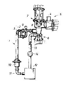
Figure 1 shows partly in section the arrangement in
accordance with the invention as it is realized on being use~
together with a filling system in a packing machine of known
type.
Figure 2 shows on a larger scale and partly in section a
coupling part in accordance with the invention in a closed
posltlon .
Figure 3 is identical with Figure 2 but shows the
coupling part in accordance with the invention in the open
position.
The arrangement in accordance with the invention, as
mentioned previously, is intended to be used together with a
packing machine of conventional type. This packing machine,
which for example may be of the type which is described in
Swedish patent application no. 8202302-9, comprises a filling
system for the filling of wholly or partly preformed packing
containers with liquid contents. The contents are,conducted
to the individual packing containers via a filling pipe 1
which comprises a contents duct 2 and a gas duct 3
concentrically surrounding the same. The contents duct 2 is
connected at its upper or rear end to a product line ~ via
which the contents are conducted to the packing machine, the
supply being controllable with the help of a product valve 5.
The rear or upper end of the gas duc~ 3 is connected to a
source of inert gas which, however, is not shown on the
drawing. The arrangement comprises, moreover, a washing
valve 6, by means of which cleaning fluid can be made to flow
through the filling pipe 1, and a shutoff valve 7 which
comprises a vapor lock and is used in the cleaning and
sterilizing of the filling system.
X
13(~5~8
In operation, i.e. when the packing machine manufactures
and fills packing containers, both ducts 2,3 of the filling
pipe 1 are connected to the product line 4 and a container of
inert gas (not shown) respectively. When the filling system
is to be washed or cleaned the filling pipe is coupled into a
circulation system for cleaning fluid, the contents duct 2
and the gas duct 3 being connected in parallel with the help
of a branch pipe 8 which is placed at the upper end of the
lo filling pipe 1. The branch pipe 8 is provided with a
pressure gauge 9 so as to allow reading of the instantaneous
pressure in the cleaning fluid when it passes the branch pipe
8. At the lower end of the filling pipe 1 is connected a
coupling part lO which in turn at its lower end is connected
via a return line 11 to a container 12 for cleaning medium in
liquid form, e.g. caustic soda. From the container 12 a
washing duct 13 leads substantially vertically upwards to the
washing valve 6. The washing du~t 13 passes a pump 14 of
known type for cleaning fluid.
The coupling part 10 at its upper end comprises a
coupling 15 of the bayonet type so as to make possible a
li~uid-tight connection to the lower end of the filling pipe
1. The coupling part 10, which is substantially cylindrical,
has an internal, concentrically situated passage 16 which is
coupled together with the contents duct 2, and a passage 17
placed concentrically around the passage 16, which is in
connection with the gas duct 3. The two passages 16,17 open
via a perforated, horizontal wall 18 into a common space 19
at the lower end of the coupling part 10, this space 19 being
connected by means of a further bayonet coupling to the
return line 11 mentioned earlier.
The wall 18 is designed as an internal flange in the
coupling part 10 and has a vertical cylindrical part which is
~3C~6S~8
connected in a liquid tight manner to the lower end of the
passage 16. The said cylindrical part supports on the
outside an annular valve body 20 which preferably has a
conical or bell-shaped form and which is maintained at a
distance above the wall 18 with the help of a spring 21,
which is in the form of a helical compression spring, or
preferably, a wave-spring. The wall 18 comprises a number of
flow openings 22, which are placed in annular arrangement and
at such a distance from the vertical centre axis of the
coupling part 10 that they are covered, wholly or partly, by
the valve body 20 when the same is in its lower position,
where it rests with a sealing surface facing downwards
against the wall 18. The valve body 20 together with the
flow openings in the wall 18 forms a passage creating a
Venturi effect, which endeavours to move the valve body
downwards to rest against the valve seat 18 when the cleaning
fluid flows past-from the top, which will be explained in
more detail in the following.
When the packing machine with the arrangement in accordance
with the invention, after operation over a longer or shorter
time, is to be stopped, the connection of the filling pipe to
the product line 4 is cut off first of all with the help of
the product valve 5, which is put into its closed position
shown in Figure 1.
Subsequently the original connecting part (not shown), which
connects the filling pipe with the valve housing and inert
gas source respectively, is removed, and the branch pipe 8
with the pressure gauge 9 is placed so that it connects, as
shown in Fig. 1 the valve housing provided with the valves
5,6 and 7 to the two ducts 2,3 of the filling pipe 1, which
thus are coupled in parallel. After the outside of filling
pipe 1 has possibly been cleaned and valves, extension pipe
X
~3V6~
or other components located at the lower part of the filling
pipe 1 have been removed, the lower end of the filling pipe
is connected in a liquid-tight manner to the upper opening of
the coupling part 10 (Fig. 2,3). The two ducts 2,3 thus will
converge via the coupling part 10 and be connected to the
return duct 11 and the container 12 for cleaning fluid, from
which the washing duct 13 via the pump 14 conducts to the
washing valve 6. As a result a closed circulation system is
produced comprising the two ducts 2,3 of the filling pipe 1
(coupled in parallel), the coupling part 10, the return duct
11, the container 12, the washing duct 13, the valve housing
and the branch pipe 8. The washing now commences in that the
washing pump 14 is started and the washing valve 6 is opened,
thus allowing the cleaning fluid (usually caustic soda) to
circulate through the system as indicated by means of arrows.
In the course of this the cleaning fluid will flow through
- the valve housing, via the branch tube 8 and through the
contents duct 2 and the gas duct 3. The circulation of
cleaning fluid continues during a certain, predetermined time
whilst the flow through the pump 14 as well as the pressure
in the branch pipe 8 are continuously monitored.
The cleaning fluid flowing through the system, after it
has passed the contents duct 2 and the gas duct 3, enters
into corresponding passages 16 and 17 respectively of the
coupling part 10. The cleaning fluid flowing through the
contents duct 2 and the passage 16 can freely pass the
coupling part 10 to be conducted further into the circulation
system. The cleaning fluid which passes the gas duct 3 is
conducted into the outer, annular passage 17 of the coupling
part 10 and thus has to pass the valve body 20 and the flow
openings 22 in the wall 18 serving as a valve seat. Owing to
the Venturi effect the cleaning fluid will act, against the
effect of the spring 21, upon the valve body 20 in the
X
13(9~S88
direction towards its lower (that is to say closed) position,
but in normal operation the Venturi effect will not be strong
enough to enable it to close the valve. However, the
increased resistance causes considerably more than half the
cleanin~ fluid flow to pass through the contents duct 2, and
in a packing machine of the aforementioned type the total
flow of approx. 5500 l/h is divided so that approx. 1500 l/h
pass the gas duct 3 and the outer passage 17, whereas approx.
4000 l/h pass through the central contents duct 2 and the
passage 16. This is desirable, since it is only the contents
duct 2 which normally comes into contact with the contents
and which, therefore, requires cleaning.
When larger residues of contents, particles or other
improper objects are present in the contents duct it can
happen that the latter becomes wholly or partially blocked.
If this happens in the arrangement in accordance with the
invention, a greater part of the cleaning fluid will seek to
pass through the gas duct 3 whereby the increased flow
through the passage and past the valve body 20 creates a
vigorous Venturi effect which is capable of overcoming the
force of the spring 21 and pressing the valve body 20 further
downwards, closer to the wall 18 serving as a valve seat. As
a result the flow through the passage 17 and the gas duct 3
is limited further so that, even if the contents duct 2 is
completely blocked, it is not allowed to rise to any
appreciable degree (max. approx. 25% above the normal value,
that is to say at the most approx. 1900 l/h in the
aforementioned machine type). This results in a pressure
increase in the system which can be read with the help of the
pressure gauge 9, so that an indicat on of the contents duct
2 being wholly or partially blocked is obtained. The
pressure increase created naturally brings with it also a
rise in pressure to a corresponding degree in the contents
X
13(~6S~E~
duct 2, which contributes to any residues of contents
sticking in the contents duct 2 being pressed out and removed
more readily. The arrangement in accordance with the
invention thus creates better preconditions for an effective
cleaning of the contents duct 2 even if the same is wholly or
partially blocked at the start. If, in spite of this, a
cleaning of the contents duct 2 should prove impossible, this
is clearly indicated by the pressure gauge 9, so that the
machine operator can dismantle the filling pipe and manually
clean the same. When a centrifugal pump is used the pressure
rise in the cleaning fluid will be small and difficult to
read on the pressure gauge 9. However, in any case the
reduced flow will result in a detectable change of the
emptying rate in the tank 12, which indicates that the duct 2
is partially blocked. After the cleaning or washing process
has been completed the valve 7 too is closed, whereupon the
system possibly can also be sterilized with the help of some
suitable sterilizing agent, e.g. hydrogen peroxide, which is
allowed to circulate through the filling pipe. This
technique is known, however, and does not require to be
described in detail in this context.
X