Note : Les descriptions sont présentées dans la langue officielle dans laquelle elles ont été soumises.
~3~
Description
Accelerator for an indirectlY o~eratin~ air brake
The invention relates to an accelerator on indirectly
operating air brakes, particularly for railway vehicles,
having a bleed valve, an actuating member which operates
via an unlatchable intermediate link to open the bleed
valve, and a chamber connected via the valve to the main
air line and vented via a throttling port.
In one prior art accelerator of this type a two-armed
lever is swivel-hinged on the actuating member. The
upper arm of the lever i5 bifurcated. One arm of the
fork cooperates with a bleed valve slide rod and the
other arm of the fork cooperates with a breaker piston.
The lever can be swivelled about a pin. A spring which
rests on the lower arm tries to swivel the two-armed
lever into its latched position. The two-armed lever can
be unlatched by means of the breaker piston.
This prior art lever is both difficult to manu~acture and
difficult to install and therefore needs to be replaced
by another member that can be more easily manufactured
and installed.
In accordance with the invention this object is achieved
by the fact that the unlatchable intermediate link is in
the form of a rotationally symmetrical tappet and is held
in its operational position by a spring.
One working example of the accelerator of the invention
will now be described in detail with the aid of the
accompanying drawing, wherein;
Fig. 1 shows an axial section through an accelerator,
'
Fig. 2 shows a view of a tappet.
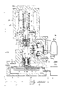
In Fig. l the accelerator has an actuating member, with a
piston 2 to which a diaphragm 3 is attached. A plate-
shaped part ~ of the piston 2 can be seen below the
diaphragm 3. The diaphragm 3 divides a cylindrical
compartment into two chambers 5 and 6. The lower c~lamber
5 is connected via a line 7 to a control air tank 7a.
The upper chamber 6 is connected to the main air lil1e 6.
At the rim of the piston 2 there is fixed a bushing 8, in
which a tappet lO rests on a block 9. A spring ll t,ries
to push the tappet lO against the block 9 via a second,
movable bushing 12, and so keep the tappet lO in the
vertical position shown. Above a cam 13 (see Fig. 2) of
this tappet lO there is a slide rod 14, which is part of
a bleed valve 30 described below. A breaker piston 16
likewise is supported laterally on the tappet lO. 'l'his
breaker piston 16 can swivel the tappet lO out of the
range of the slide rod 14, as will be described in more
detail below. Three diaphragms 17, 18 and l9 abut ~he
breaker piston. To the left of tl1e first diaphraym 17, a
chamber 20 i,s connected to chamber 6 via a bore 21, said
chamber 6 communicating with the main air :line 6a, as
already m~ntioned. Between diaphrayms 17 and 18 a
further chamber 22 is connected to the outside air (the
atmosphere) via a line 23. ~etween diaphragms 18 alld l9
a chamber 24 is connected to the brake cylinder 26 via a
line 25. To the right of the third diaphragm 19, a
chamber 27 is connected via a line 28 to a chamber 18 in
a housing 29 detailed below. Between chamber 6, which is
connected to main air line 6a, and the housing 29 there
is provided a bleed valve 30 having a valve seat 31 and a
valve body 32. A sealing wash0r 33 is attached to the
valve body 32, and when the valve 30 is closed it rests
on the valve seat 31. The valve body 32 is joined to a
piston 34 permanently fixed on the slide rod 14, and a
I
diaphragm 35 abuts said piston 32. This diaphragm 35 i5
attached to the bottom end of a cylinder 36, which
surrounds a chamber 37 which projects into the hou~ir-g 29
and at the top end is attached to the housing 29.
Diaphragm 35 thus subdivides the housing 29 into the two
chambers 37 and 38. These two chambers 37 and 3~ are
interconnected by a throttle point 39. The outer chamber
38 is connectd to the outside air by a throttling port
40. A spring 41, one side of which rests against the
piston 34 and the other side against the lid 29a o~ the
housing 29, tries to push the piston 34 downwards and so
press the valve body 32 against the valve seat 31, so
that the bleed valve 30 is closed.
The control air tank 7a is joined to the main air line 6a
by a line 42, in which a shut-of~ valve 43 is provided.
The brake cylinder 26 is joined by a line 25a to the main
control member (not shown).
In Fig. 2 the tappet 10 has at its top end the cam 13
already mentioned, which protrudes beyond a conical
surface 15 of the tappet 10. As long as the tappet lO in
Fig. 1 is in its vertical position, the slide rod 14 o~
the bleed valve 30 is able to rest on said cam 13. C
the breaker piston 1~ causes the tappet 10 to be tilted,
the slide rod 14 i5 ~irst cleared by the cam 13 and th~n
by the conical surface 15. The tappet 10 furthermore has
a spherical chamfer 44 at its bottom end, as well as a
conical disc 45. The spring 11 presses the above-
mentioned movable bushing 12 against said disc 45 and
tries to swivel the tappet lO into its vertical position.
In its lower portion the tappet lG has a recess 46 so
that when the tappet 10 becomes tilted it does not hit
the bushing 12.
The foregoing accelerator operates as follows:
With the brake released, the air pressure in control air
tank 7a equals the air pressure in main air line 6a. The
piston 2 is situated in its bottommost position. The air
pressure in chamber 20 is the same as in main air line
6a, whereas the pressure in chambers 22, 24 and 27 is
that of the outside air (atmosphere). The piston 16 is
thus in its extreme right-hand position. The spring 11
holds the tappet 10 in its vertical position. The cam 13
is beneath the slide rod 14. The bleed valve 30 is
closed due to the action of the spring 41. Both chambers
37 and 38 are vented.
When the brake is operated the pressure in the main air
line 6a falls in the usual way. The air pressure in
chamber 6 above the piston 2 of the actuating member 1
becomes lower than the air pressure in chamber 5, where
the pressure is the same as in control tank 7a. Thi.s
therefore raises the piston 2 with the tappet 10. The
cam 13 knocks the slide rod 14 up~ards and the valve body
32 i5 raised with the slide rod 14 against the action of
the spring 41, causiny the bleed valve 30 to open. The
air from the main air line 6a flows out Oe chamber 6 into
chamber 38 of the accelerator housiny 2~, arlcl esclp,~s
into the open throucJh the throttlirlg port 40. An aLr
pressure which keeps the valve 30 open is exerted oll
diaphragm 35. F'rom chamber 38 air flows along lirle 28
into chamber 27 and pushes against diaphragm 19. Tlle air
pressure acting on diaphragm 19 causes the piston 16 to
be displaced to the left, which swivels the tappet lO and
makes the cam 13 disengage itself from the slide rocl 14.
The action of braking causes a brake pressure to build up
in the brake cylinder 26 in per se known manner. This
brake pressure is transmitted along line 25 clnd through
chamber 24 to diaphragm 18, and holds the piston 16 its
extreme left-hand position. The piston 16 remains in
this position until the brake is released.
~3~
~,
Whilst the air pressure in the main air line f a115 by the
amount necessary for the control valve to respond, a
pressure builds up in chamber 37 through throttling port
39 and acts on the piston 3~. This pressure is supported
by the force of the spring 41, with the result that the
piston 34 falls and the valve 30 is closed.
While the brake is being released, the pressure in the
main air line 6a rises again to the control pressure.
This makes the piston 2 resume its illustra~,ed starting
position. At the same time the brake cylinder 26 empties
and the piston 16 likewise moves into its illustrated
starting position. Just how long the bleed valve 30
remains open during braking depends in this system only
on the dimensions of the throttle points 39 and 40, not
on the size of accelerator chamber 38. This makes it far
easier to regulate the accelerator.
However, if braking takes place several times in close
succession, it is possible that the brake will not yet
have been fully released. In particul~r this will mean
that the piston 2 has not yet moved back into itS
bottommost position. Brake cylinder Z6 ~ and hence via
line 25 chamber 24 likewise - are already vented ~ n~ tlle
piston 16 has already moved to the riyht in Fig. 1.
Conical surface 15 will thereore now knock against slide
rod 1~. Thus when there is repeated braking, bleed valve
30 is not opened by the cam 13, as in the first case, but
by conical surface 15. Vepending on the position of
piston 2, the slide rod 1~ will therefore rest more in
the middle or more at the edge of conical surface 15.
Conical surface 15 ensures that irrespective of the
JL~O ~ O~
position of piston 2 and thus of the axial position r~f
tappet 10, when tappet 10 is released by piston 16 the
conical surface 15 can support the slide rod 14 and thus
repeated opening of the bleed valve 30 is ensured.
"', ;
', ':'