Sélection de la langue

Search

Sommaire du brevet 1306941 

Énoncé de désistement de responsabilité concernant l'information provenant de tiers

Une partie des informations de ce site Web a été fournie par des sources externes. Le gouvernement du Canada n'assume aucune responsabilité concernant la précision, l'actualité ou la fiabilité des informations fournies par les sources externes. Les utilisateurs qui désirent employer cette information devraient consulter directement la source des informations. Le contenu fourni par les sources externes n'est pas assujetti aux exigences sur les langues officielles, la protection des renseignements personnels et l'accessibilité.

Disponibilité de l'Abrégé et des Revendications

L'apparition de différences dans le texte et l'image des Revendications et de l'Abrégé dépend du moment auquel le document est publié. Les textes des Revendications et de l'Abrégé sont affichés :

  • lorsque la demande peut être examinée par le public;
  • lorsque le brevet est émis (délivrance).
(12) Brevet: (11) CA 1306941
(21) Numéro de la demande: 1306941
(54) Titre français: GUIDE DE COUPE
(54) Titre anglais: CUTTING GUIDE
Statut: Périmé et au-delà du délai pour l’annulation
Données bibliographiques
(51) Classification internationale des brevets (CIB):
  • B26B 29/06 (2006.01)
  • A47G 27/04 (2006.01)
  • B23D 51/02 (2006.01)
  • B26F 01/38 (2006.01)
  • B44C 07/08 (2006.01)
(72) Inventeurs :
  • WARD, JONATHAN (Royaume-Uni)
(73) Titulaires :
  • DURALAY LIMITED
(71) Demandeurs :
  • DURALAY LIMITED (Royaume-Uni)
(74) Agent: ROBIC AGENCE PI S.E.C./ROBIC IP AGENCY LP
(74) Co-agent:
(45) Délivré: 1992-09-01
(22) Date de dépôt: 1988-10-03
Licence disponible: S.O.
Cédé au domaine public: S.O.
(25) Langue des documents déposés: Anglais

Traité de coopération en matière de brevets (PCT): Non

(30) Données de priorité de la demande:
Numéro de la demande Pays / territoire Date
87.23224 (Royaume-Uni) 1987-10-02

Abrégés

Abrégé anglais


ABSTRACT OF THE DISCLOSURE:
A cutting guide for use in making a cut in a carpet
comprises an elongate base having a flat bottom surface and
two upper ramp surfaces separated at the apex by two
channels which extend along the base. The guide walls of
the channels are at opposite oblique angle relative to the
upper ramp surfaces so that when the guide is placed
underneath a carpet and a knife drawn along the channel in
contact with a guide wall, the cut edge thereby produced in
the carpet is at an oblique angle to the plane of the
carpet. When two such edges of different portions of carpet
are abutted together, a tidy unobtrusive seam is produced.

Revendications

Note : Les revendications sont présentées dans la langue officielle dans laquelle elles ont été soumises.


The embodiments of the invention in which an exclusive
property or privilege is claimed are defined as follows:
1. A cutting guide for use in guiding a cutting tool of the
type used to cut flexible sheet material such as carpet or
the like, said guide comprising a base having a generally
flat bottom surface, said base having inclined upper ramp
surfaces to support the carpet to be cut, said guide having
an apex portion at the juncture between said ramp surfaces,
said apex defining at least two parallel upwardly open
channels having oppositely inclined channel guide walls,
which guide walls are inclined at opposite angles relative
to a normal to the flat bottom surface of at least 20°.
2. A cutting guide according to claim 1, wherein said ramp
surfaces are inclined with respect to the flat bottom
surface of the guide at an angle of at least approximately
7°.
3. A cutting guide according to claim 1 or 2, wherein the
angle defined by the guiding surfaces associated with the
first and second upwardly open channels defines an angle in
the range between 40 and 70°.
4. A cutting guide according to claim 1 or 2, wherein said
parallel channels define a ridge therebetween, each of said
parallel channels also including an opposite channel wall
parallel to the above mentioned guide surface wall, and each
channel further including an inner wall oriented
transversely with respect to these parallel side walls of
each of said channels.
5. A cutting guide according to claim 1 or 2, wherein said
base has an end face defining an interlocking configuration
- 7 -

such that the guide can be joined to another guide of the
same geometry to increase the effective length of a guide
constructed in accordance with the present invention.
6. A cutting guide according to claim 5, wherein another
end of the guide is mitred to form end faces which are
useful when cutting carpet at an acute angle.

Description

Note : Les descriptions sont présentées dans la langue officielle dans laquelle elles ont été soumises.

13C~69'-~1
1 Agent's Ref 2718PCT
CUTTING GUIDE
The invention relates to a guide for use in making a cut in a flexible
sheet member such as a carpet.
The laying of floor coverings such as carpets often necessitates the - -
forming of straight seams, which are to be as tidy and unobtrusive as
possible.
Carpets are often formed of tufts of material embedded in a flexible
backing. A problem arises when forming straight edges in portions of
carpet which need to be abutted together. A cut often leaves half cut
tufts and missing tufts along the cut edge of the carpet. When a seam
is formed between two such edges of adjd ning portions of carpet, the
result is an obtrusive seam or "valley" of missing tufts.
:
There is a need to form an edge in a portion of flexible sheet member or
floor covering such as a carpet, so that a tidy unobtrusive seam will be
made when that edge is abutted against another edge, eg, of another
portion of carpet.
?
~; :
:: ~
,

13(~6~
- 2 -
According to one aspec-t of the invention, there is provided
a guide for use in making a cut in a flexible sheet
material such as~a carpet or the like the guide comprising
a base having a generally flat bottom surface, the base
having inclined upper ramp surfaces to support the carpet to
be cut, the guide having an apex portion at the juncture
between the ramp surfaces, the apex defining at least two
parallel upwardly open channels having oppositely inclined
channel guide walls, which guide walls are inclined at
opposite angles relative to a normal to the flat bo-ttom
surface of at least 20.
In a preferred embodiment, the opposing inner side walls of
the channel are inclined downwardly and diverge at a first
angle.
Preferably the floor of the channel includes a generally
central longitudinal ridge to divide the channel into two
portions.
In another aspec-t of the invention there is provided a
method of joining two portions of a carpet or like sheet
material in side-by-side relation comprising the steps of:
placing the channel of a guide according to the invention
under the margin of the first portion of the carpet;
inserting the blade of a knire in the channel and urging the
blade towards that inner side wall of the channel which is
adjacent the body of the carpet;
-
-
.. .
~''

~IL3~?69~1
3 A~ent's Ref 2718PCT
moving the knife along the channel so as to m~ke a cut along the length
of the carpe-t, at an oblique angle to the plane of the carp~t;
discarding the marginal strip thereby cut off;
placing the second portion of carpet to be joined so that its margin
overlies the channel and
repeating the above steps;
removing the guide; and
allowing the cut edges to fall together and sticking them with an
adhesive or sewing them together.
Guides for cutting heavy fabrics such as rugs are known from US
3,772,793,but this guide is not for use in p.roducing an oblique cut.
In order that the invention may be better understocd it will be
described with reference to the acccmpanying drawings in which;
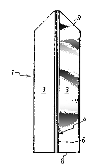
Figure 1 is a plan view from above of one e~bodiment of the guide of the
invention;
and Figures 2 and 3 are schematic views from one end of a guide
according to Figure 1 in use.
The guide comprises an elongate base 1 formed, eg, as an extrusion frcm
aluminium, lightweight allcy or the like. The base 1 has a substantially
flat bottom surface.2. The upper surface is formed with two
. .~
. . .

~306~
4 Agent's Ref 2718PCT
opposing upper ramp surfaces 3 and an elongate channel 4 extends along
the apex of the base 1. The inner side walls 5 of the channel 4 extend
downwardly frcm the upper surface and diverge from each other at a first
angle. A short raised ridge 6 (Fig 2) extends longitudinally along the
centre of the floor of the channel 4, the side walls of the ridge 6
extending generally parallel to the facing inner side walls 5, better to
guide a knife blade 11 to cut along a predetermined path, as explained
belcw.
The guide is formed with elongate holes 7 extending inwardly to the base
1 from one end face 8. Lengths of dcwling or similar (not shown) may be
received in these holes 7 to join one guide to another in an end-to-end
relation. The other end face 9 of the base 1 is mitred. In this way,
the guide may easily be moved along under a carpet. The mitred end face
9 is also useful when it is desirable to cut the carpet at an angle of
45 relative to a wall.
In use, the guide is placed under the margin of the first portion of a
carpet or flexible sheet member 10 to be joined, and as shown in Figure
2. The blade of a cutting tool, such as a knife 11 is inserted into one
end of the channel 4 and urged towards the inner wall 5 of the channel 4
underlying the body of the carpet 10. The blade 11 is then moved along
the c~.annel 4 so as to make a cut along the length of the carpet at a
shallow oblique angle deter~ined by the angle of inclina-tion of the
respective channel side wall 5 relative to the ramp surfaces 3. The
.
, ^ .

13(~ii9~1
-- 5
knife blade ll is guided between the respec-tive inner side
walls 5 and the Eacing side of -the ridge 6. The marginal
strip thereby formed is then discarded. As shown in Figure
3, the first portion of carpet 10 is moved out of the way
and the second portion of -the carpet 10 to be joined is then
placed on the guide with its margin overlying the channel 4.
The blade of the cutting tool 11 is then inserted in the
channel 4 and is urged towards wi-th that inner wall 5
adjacen-t the second portion of carpet 10 and is moved
therealong so as to make a cut along the length of the
carpet 10 in a similar manner as that just described. The
marginal strip on the second portion of carpet is then also
discarded. In this way, the two edges have inclined
surfaces which correspond to the angle of inclination of the
channel 4 of the guide.
The guide is then removed, and the two cut edges are allowed
or caused to fall together. The edges of the flexible
member or carpet may be stuck down to a floor, sewn together
or otherwise, to produce a tidy unobtrusive seam.
In the embodiment shown the width of the base 1 is
substantially 10.16 cm, the height from the apex to the
underside 2 is 0.95 cm, the width of the channel 4 at the
top is 0.15 cm and the depth of the channel 4 is 0.48 cm.
The angle formed between the lower end of the inner side
walls 5 and the adjacent floor is about 20 or more. The
ramp portions 3 are inclined at a second angle 7 to the
horizontal. The opposed side walls 5,5 of the two channels
are inclined downwardly and diverge at an angle of
substantially 70 in the preferred embodiment. The
invention i8 not limited to the embodiment shown. The
guide may be diestamped from a sheet of stainless steel or
the like. The inner side walls 5 of the channel 4 may be

~06~
substantially parallel to each other, and the ramp portions
inclined at a more acute angle. The end faces 8, 9 may be
formed with interlocking lugs or bayonets so that many
guides may be connected together in an end-to-end relation
so as to extend the length of the channel 4c The ends of
the guide may also be mitred -to form end faces useful when
cutting carpet at an acute angle.
.~ .
. ~

Dessin représentatif
Une figure unique qui représente un dessin illustrant l'invention.
États administratifs

2024-08-01 : Dans le cadre de la transition vers les Brevets de nouvelle génération (BNG), la base de données sur les brevets canadiens (BDBC) contient désormais un Historique d'événement plus détaillé, qui reproduit le Journal des événements de notre nouvelle solution interne.

Veuillez noter que les événements débutant par « Inactive : » se réfèrent à des événements qui ne sont plus utilisés dans notre nouvelle solution interne.

Pour une meilleure compréhension de l'état de la demande ou brevet qui figure sur cette page, la rubrique Mise en garde , et les descriptions de Brevet , Historique d'événement , Taxes périodiques et Historique des paiements devraient être consultées.

Historique d'événement

Description Date
Inactive : CIB de MCD 2006-03-11
Le délai pour l'annulation est expiré 2004-09-01
Lettre envoyée 2003-09-02
Accordé par délivrance 1992-09-01

Historique d'abandonnement

Il n'y a pas d'historique d'abandonnement

Historique des taxes

Type de taxes Anniversaire Échéance Date payée
TM (catégorie 1, 5e anniv.) - générale 1997-09-02 1997-08-29
TM (catégorie 1, 6e anniv.) - générale 1998-09-01 1998-08-19
TM (catégorie 1, 7e anniv.) - générale 1999-09-01 1999-08-18
TM (catégorie 1, 8e anniv.) - générale 2000-09-01 2000-08-16
TM (catégorie 1, 9e anniv.) - générale 2001-09-03 2001-08-17
TM (catégorie 1, 10e anniv.) - générale 2002-09-03 2002-08-16
Titulaires au dossier

Les titulaires actuels et antérieures au dossier sont affichés en ordre alphabétique.

Titulaires actuels au dossier
DURALAY LIMITED
Titulaires antérieures au dossier
JONATHAN WARD
Les propriétaires antérieurs qui ne figurent pas dans la liste des « Propriétaires au dossier » apparaîtront dans d'autres documents au dossier.
Documents

Pour visionner les fichiers sélectionnés, entrer le code reCAPTCHA :


Pour visualiser une image, cliquer sur un lien dans la colonne description du document. Pour télécharger l'image (les images), cliquer l'une ou plusieurs cases à cocher dans la première colonne et ensuite cliquer sur le bouton "Télécharger sélection en format PDF (archive Zip)" ou le bouton "Télécharger sélection (en un fichier PDF fusionné)".

Liste des documents de brevet publiés et non publiés sur la BDBC .

Si vous avez des difficultés à accéder au contenu, veuillez communiquer avec le Centre de services à la clientèle au 1-866-997-1936, ou envoyer un courriel au Centre de service à la clientèle de l'OPIC.


Description du
Document 
Date
(aaaa-mm-jj) 
Nombre de pages   Taille de l'image (Ko) 
Abrégé 1993-11-03 1 18
Revendications 1993-11-03 2 44
Dessins 1993-11-03 1 29
Description 1993-11-03 6 162
Dessin représentatif 2000-07-12 1 8
Avis concernant la taxe de maintien 2003-10-27 1 173
Taxes 1996-09-18 1 42
Taxes 1995-08-16 1 74
Taxes 1994-08-18 1 75