Sélection de la langue

Search

Sommaire du brevet 1307164 

Énoncé de désistement de responsabilité concernant l'information provenant de tiers

Une partie des informations de ce site Web a été fournie par des sources externes. Le gouvernement du Canada n'assume aucune responsabilité concernant la précision, l'actualité ou la fiabilité des informations fournies par les sources externes. Les utilisateurs qui désirent employer cette information devraient consulter directement la source des informations. Le contenu fourni par les sources externes n'est pas assujetti aux exigences sur les langues officielles, la protection des renseignements personnels et l'accessibilité.

Disponibilité de l'Abrégé et des Revendications

L'apparition de différences dans le texte et l'image des Revendications et de l'Abrégé dépend du moment auquel le document est publié. Les textes des Revendications et de l'Abrégé sont affichés :

  • lorsque la demande peut être examinée par le public;
  • lorsque le brevet est émis (délivrance).
(12) Brevet: (11) CA 1307164
(21) Numéro de la demande: 1307164
(54) Titre français: METHODE ET DISPOSITIF POUR LE FORMAGE D'UN PRODUIT D'EXTRUSION
(54) Titre anglais: SHAPING DEVICE
Statut: Durée expirée - après l'octroi
Données bibliographiques
(51) Classification internationale des brevets (CIB):
  • A23G 9/04 (2006.01)
  • A23G 9/22 (2006.01)
  • A23G 9/28 (2006.01)
(72) Inventeurs :
  • BINLEY, GARY NORMAN (Royaume-Uni)
  • GILES, ALAN FREDERICK (Royaume-Uni)
  • PEARSON, CHRISTOPHER ANTHONY (Royaume-Uni)
  • BAKER, TERENCE PAUL (Royaume-Uni)
(73) Titulaires :
  • UNILEVER PLC
(71) Demandeurs :
  • UNILEVER PLC (Royaume-Uni)
(74) Agent: SMART & BIGGAR LP
(74) Co-agent:
(45) Délivré: 1992-09-08
(22) Date de dépôt: 1989-01-13
Licence disponible: S.O.
Cédé au domaine public: S.O.
(25) Langue des documents déposés: Anglais

Traité de coopération en matière de brevets (PCT): Non

(30) Données de priorité de la demande:
Numéro de la demande Pays / territoire Date
8800764 (Royaume-Uni) 1988-01-14
8807450.5 (Royaume-Uni) 1988-03-28

Abrégés

Abrégé anglais


Q 7083 (R)
ABSTRACT
Shaping device and method for shaping extrudable
material comprising at least one extrusion nozzle having
feeding means for extrudable material and being
supported in a carrier common to all nozzles, motor
means for moving either the carrier or a movable support
surface for receiving extruded material directly from
the nozzles and a programmable computer for controlling
the motor means.
******

Revendications

Note : Les revendications sont présentées dans la langue officielle dans laquelle elles ont été soumises.


THE EMBODIMENTS OF THE INVENTION IN WHICH AN EXCLUSIVE
PROPERTY OR PRIVILEGE IS CLAIMED ARE DEFINED AS FOLLOWS:
1. Apparatus for shaping extrudable material comprising:
at least one extrusion nozzle and a movable support
surface disposed at a controllable distance from
the nozzle for directly receiving extruded product
therefrom,
each nozzle having feeding means for feeding
extrudable material thereto and provided with valve
means positioned a sufficiently small distance from
the nozzle opening as to prevent, in use, leakage
of material from the nozzle opening following
closure of the valve means,
all said nozzles being supported on a common carrier
which is at least rotatable with respect to said
support surface about an axis of rotation other
than an axis of complete rotational symmetry of all
said nozzles,
motor means for effecting relative movement between
the carrier and the support surface, and
programmable computer means for programmably
controlling said motor means to provide both
relative rotational and translational movement in
at least one direction between the carrier and the
support surface, and for programmably controlling
the actuation of the valve means of said nozzles.
2. Apparatus for shaping extrudable material according to
claim 1, wherein the valve means of each of said nozzles
is positioned at a distance of at most 5 cm from the
nozzle opening.
3. Apparatus for shaping extrudable material according to
claim 1, wherein the valve means of each nozzle is
positioned at a distance of at most 3 cm from the nozzle
opening.

4. Apparatus for shaping extrudable material according to
claim 1, 2 or 3, wherein said carrier is mounted on a
frame having guides along which the carrier is movable in
at least two orthogonal directions.
5. Apparatus for shaping extrudable material according to
claim 1, 2 or 3, wherein said apparatus further comprises
means for moving said carrier up and down with respect to
the support surface.
6. Apparatus for shaping extrudable material according to
claim 1, 2 or 3, wherein said apparatus further comprises
means for moving the carrier up and down with respect to
the support surface, and wherein a conveyor belt forms the
movable support surface.
7. Apparatus for shaping extrudable material according
to claim 1, 2 or 3, wherein the motor means are stepper
motors.
8. Apparatus for shaping extrudable ice confection
material to form a shaped ice confection product, said
apparatus comprising:
a plurality of extrusion nozzles supported on a common
carrier rotatable about an axis of rotation which
is non-coincident with any axis of complete
rotational symmetry of all nozzles, each nozzle
having means for feeding ice confection material
thereto and having valve means positioned therein
at a sufficiently small distance from the nozzle
opening to prevent leakage of ice confection
material from the nozzle opening following closure
of the valve means,
elongate movable conveyor means disposed below and
spaced from the openings of said nozzles for
providing a support surface for directly receiving
ice confection material extruded from said nozzles,

first motor means for driving said conveyor means and
effecting translational movement of said support
surface,
means including second motor means for driving said
carrier in rotation about said axis of rotation and
translationally in at least one direction relative
to said support surface, and
means including a programmable computer for
programmably controlling the opening and closing of
the valve means of said nozzles and actuation of
the first motor means and the means including
second motor means so as to lay down on the movable
support surface an ice confection product having a
shape dependent upon the distance between the
nozzle opening and the support surface and the
rotational speed of said carrier.
9. Apparatus for shaping extrudable ice confection
material according to claim 8, wherein said carrier is
supported on a frame having guides along which the carrier
is movable in at least two orthogonal directions.
10. Apparatus for shaping extrudable ice confection
material according to claim 9, wherein one of said
directions of movement of the carrier is up and down
relative to the support surface for adjusting the distance
between the nozzles and the support surface.
11. Apparatus for shaping extrudable ice confection
material according to claim 8, 9 or 10, wherein the valve
means of each nozzle is positioned at a distance of at
most 5 cm. from the nozzle opening.
12. A process for preparing a shaped food product from
extrudable material comprising the steps of:
extruding the extrudable material from at least one
extrusion nozzle provided with valve means
positioned sufficiently close to the nozzle opening

as to prevent leakage of material from the nozzle
opening following closure of the valve means and
which is rotatable about an axis of rotation which
is non-coincident with any axis of complete
rotational symmetry of all nozzles, directly onto a
movable support surface which is arranged at some
distance below the opening of said at least one
nozzle for translational movement relative thereto,
and
using programmable computer means programming the
opening and closing of the valve means of said
nozzles and the driving of said nozzles in rotation
about said axis of rotation and translationally in
at least one direction, which rotation and
translation is relative to the support surface, to
lay down on the movable support surface a food
product of desired shape.
13. A process for preparing a shaped ice confection
product from extrudable ice confection material comprising
the steps of:
extruding the extrudable ice confection material from
three extrusion nozzles each having valve means
therein positioned sufficiently close to the nozzle
opening as to prevent leakage of material therefrom
following closure of the valve means, and all
supported in angularly spaced relationship on a
common carrier which is rotatable about a
vertically-oriented axis of rotation, downwardly
onto a horizontally-oriented support surface
provided by an elongate conveyor arranged some
distance below the nozzle openings and travelling
in a direction orthogonal to the axis of rotation
of the carrier, and
using programmable computer means programming the
travel of said conveyor, the opening and closing of
the valve means in said nozzles, and direction and
speed of rotation of said carrier to form on the

11
support surface an ice confection product of
desired shape.

Description

Note : Les descriptions sont présentées dans la langue officielle dans laquelle elles ont été soumises.

~3~'7~
~ 70~3 (R)
S~APING DEVICE
The invention relates to a shaping device for extrudable
material, for example for manufacturing food products,
and in particular for ice confections, the shaping
device comprising at least one extrusion nozzle and a
movable support surface arranged at some distance from
the nozzle for directly receiving extruded product
therefrom, each nozzle having feeding means for
extrudable material, all nozzles being arranged on a
common carrier, which is at least rotatable with respect
to the support surface about an axis of rotation which
is not an axis of complete rotational symmetry of all
nozzles, and motor means for effecting the relative
movement of the carrier and the support surface.
An apparatus of this general kind is described and shown
in EP 44,689, allowing the manufacture of twisted
products. However, there is continuing need of more
varied products, either as regards pattern, or ornament,
or configuration, or shape, or texture or any
combination thereof.
It is the aim of the present invention to provide a
method and apparatus for easily manufacturing such
varied and complex products.
According to the invention, this may be realized by
using a shaping device of the general kind as described
above, the motor means of which are adapted for both
relative rotational and translational movement in at
least one direction of the carrier and the support
surface, the actuation of these motor means being
controlled by a programmable computer.
~'
.

Q 7083 (R)
For even more freedom of shape and ~lexibility of
manufacture, the carrier may be mounted in a frame which
is movable along guides in a~ least two orthoyonal
directions.
For manufacturing products having a height of several
centimeters, it is to be preferred that the carrier be
movable up and down with respect to the support surface.
Even more variegation can be accomplished if the nozzles
each are provided with valve means, the action of which
is controlled by the same computer as ~he motor means,
which valve means are arranged at a small distance from
tha actual nozzle opening so that, in use, no material
will be leaking out of the nozzle opening after closing
the valve means. Usually, this distance will not be in
excess of 5 cm, and more preferably not in excess of 3
cm. As a result, a reliable action is obtained,
resulting in shapes of proper definition.
Some characteristic examples of devices according to the
invention are given below and shown in the accompanying
drawings, in which :
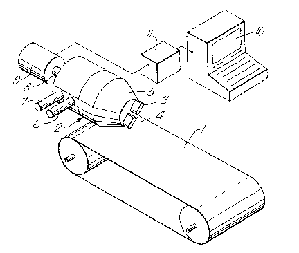
Fig. 1 is a schematic representation of a first
embodiment of a device according to the
invention.
Fig. 2 is a schematic representation of a second
embodiment of a device according to the
invention.0 Fig. 3 is a partial sectional view of a nozzle for use
in a device according to the~ invention.
Fig. 4 is a partial perspective view of a third
embodiment according to the invention.
Referring to the drawing, Fig. 1 shows a belt conveyor
1, forming a supporting surface for directly receiving

~3~
Q 7083 (~)
extruded products from an extrusion device 2 arranged
above this conveyor. The extrusion device comprises two
nozzles 3,4, which are arranged in a common carrier 5
and which each have separate supply means 6,7, through
which extrudable materials may be fed to the nozzles.
The carrier 5 is attached to, and supported by, a
central shaft 8 which may b~ driven for rotation by a
stepper motor 9. The actuation, i.e. rotational
direction, speed, acceleration, can be controlled at
will by a programmable computer 10. Usually, a stepper
motor driver unit 11 is arranged between the computer 10
and the motor 9~
The device shown in Fig. 2 al50 comprises a belt
conveyor 12, along which guides 13, 14, 15 are arranged
in three orthogonal directions. These guides are
sl~dable with respect ~o each other. Inside the guides,
stepper motors (not shown3 are accommodated which, by
suitable transmission means such as a chain or a worm
transmission, may effect a mutual movement of the guides
as indicated by the double arrows.
The guide 15 supports a carriage 1~, which is slidably
arranged on said guide and which supports an extrusion
gear. On top of the carriage, a stepper motor 17 is
supported, the shaft 18 of which is rotatably supported
in the carriage 16. The lower end of the shaft 18
supports a disc-shaped carrier 19, to which, at regular
angular distances, extrusion nozzles 20, 21, 22 are
attached. The nozzles may be supplied with extrudable
material through flexible hoses 23. The flow of material
through the nozzles can be controlled by an internal
valve, better shown in Fig. 3.

~3~
~ 7083 (R)
In Fig. 3 a longitudinal section through a nozzle 20 is
shown. This nozzle comprises a body 2~ supported on the
carrier 19. The flexible supply hose 23 is attached to a
lateral stud 25, through which material is supplied into
the body 24. Inside the body, a valve body 26 can be
reciprocated towards and from a valve seat 31 by a motor
means 27, such as a pneumatic actuator, which is
connected to the valve stem 28. The valve is shown in
the open position; the closed position is shown, using
interrupted lines.
The motor means 27 of the valves 26, the stepper motor
17 of the carrier 19 and the stepper motors arranged in
the guides are connected in a working relationship to a
programmable computing means 29. For synchronisation
with the conveyor 12, the driving means 30 of said
conveyor may be connected to the computing means too.
The term "complete rotational symmetry" in this
specification and claims is meant to refer to a figure
having rotational symmetry, resulting in a figure of the
same shape after rotation by any angle about its axis of
symmetry.
The words "move" and "movement" are used in their
broadest sense, comprising translation, rotation,
vibration, swivel/ pivor movement and any combination.
Although stepper motors are preferably used in the
devices according to the invention because of their easy
control by electronic or computing means, it should be
noted that any well-controllable motor can be used for
this purpose.
The embodiment, as partially shown in Fig. 4, comprises
a round support plate 32, which i5 rotatably mounted on,

~o~
Q 7083 (R)
and drivable by, a motor 33. On the support plate 32,
which is driven in the direction as indica~ed by the
arrow 34, extrudable material 35, extruded ~hrough three
extrusion nozzles 36, is received. By suitably
controlling the extrusion velocity and the rotational
speed of the support plate 32, differently shaped
products can be made. During the extrusion and shaping
process, the nozzles 36, which are attached to a common
central supply pipe 37 forming a carrier, are gradually
moved upwards by actuating a motor 38 which, through a
rack and a pinion drive, can move the supply pipe 37
through a fixed bearing block 39 as indicated by a
double arrow 40. A flexible hose 41 connects the supply
pipe 37 to a supply of extrudable material. Both motor
33 and motor 38 are connected to a common programmable
computer 42. If desired, this computer can be used for
controlling any valves in the nozzles 36.
The invention also relates to a process of shaping
extrudable material, an exemplary embodiment being shown
in Fig. 2, by extruding said material through at least
one extrusion nozzle 20,21,22, which is arranged with
its nozzle opening at some distance from a movable
support surface 12 for directly receiving the material
extruded therethrough, driving each nozzle for rotation
about a common axis which is not an axis of complete
rotational symmetry of all nozzles and for translation
in at least one direction, the rotation and translation
being relatively to the support surface, wherein the
rotation and the translation are controlled by a common
computer.
According to a preferred embodiment, resulting in shapes
of more proper definition, the computer means are also
adapted to control valve means arranged at a small
distance of particularly not more than 5 and pre~erably

J~7~
Q 7083 (R)
less than 3 cm from the opening of each nozzle, so that,
in use, no material will be leaking out of said opening
after closing the respective valve.
~ , .

Dessin représentatif
Une figure unique qui représente un dessin illustrant l'invention.
États administratifs

2024-08-01 : Dans le cadre de la transition vers les Brevets de nouvelle génération (BNG), la base de données sur les brevets canadiens (BDBC) contient désormais un Historique d'événement plus détaillé, qui reproduit le Journal des événements de notre nouvelle solution interne.

Veuillez noter que les événements débutant par « Inactive : » se réfèrent à des événements qui ne sont plus utilisés dans notre nouvelle solution interne.

Pour une meilleure compréhension de l'état de la demande ou brevet qui figure sur cette page, la rubrique Mise en garde , et les descriptions de Brevet , Historique d'événement , Taxes périodiques et Historique des paiements devraient être consultées.

Historique d'événement

Description Date
Inactive : Périmé (brevet sous l'ancienne loi) date de péremption possible la plus tardive 2009-09-08
Inactive : CIB de MCD 2006-03-11
Accordé par délivrance 1992-09-08

Historique d'abandonnement

Il n'y a pas d'historique d'abandonnement

Titulaires au dossier

Les titulaires actuels et antérieures au dossier sont affichés en ordre alphabétique.

Titulaires actuels au dossier
UNILEVER PLC
Titulaires antérieures au dossier
ALAN FREDERICK GILES
CHRISTOPHER ANTHONY PEARSON
GARY NORMAN BINLEY
TERENCE PAUL BAKER
Les propriétaires antérieurs qui ne figurent pas dans la liste des « Propriétaires au dossier » apparaîtront dans d'autres documents au dossier.
Documents

Pour visionner les fichiers sélectionnés, entrer le code reCAPTCHA :


Pour visualiser une image, cliquer sur un lien dans la colonne description du document. Pour télécharger l'image (les images), cliquer l'une ou plusieurs cases à cocher dans la première colonne et ensuite cliquer sur le bouton "Télécharger sélection en format PDF (archive Zip)" ou le bouton "Télécharger sélection (en un fichier PDF fusionné)".

Liste des documents de brevet publiés et non publiés sur la BDBC .

Si vous avez des difficultés à accéder au contenu, veuillez communiquer avec le Centre de services à la clientèle au 1-866-997-1936, ou envoyer un courriel au Centre de service à la clientèle de l'OPIC.


Description du
Document 
Date
(aaaa-mm-jj) 
Nombre de pages   Taille de l'image (Ko) 
Revendications 1993-11-04 5 161
Dessins 1993-11-04 2 73
Page couverture 1993-11-04 1 13
Abrégé 1993-11-04 1 12
Description 1993-11-04 6 200
Dessin représentatif 2000-08-09 1 15
Taxes 1995-08-09 1 58
Taxes 1994-08-08 1 226
Taxes 1996-08-12 1 60