Note : Les descriptions sont présentées dans la langue officielle dans laquelle elles ont été soumises.
1 307643
RIGID INSULATION CORNER FASTENER
The invention relates to a fastener for securing
rigid insulation panels in place and, more particularly, to a
corner fastener for securiDg the corners of adjacent rigid
insulation boards without puncturing the rigid insulation
boards.
Rigid board-t`ype insulation, utilized under roofing
has been secured in place to the underlying surface or
substrate by many methods. The vast majority, approximately
~9% are secured by oDe of three methods outlined in the
following summary.
On sloped roofs, usually having a slope of over 3
inches per foot, nails with either common or with large flat
head~ are randomly spaced and driven through the insulation
into the sub0trate. Thi3 method is used when the succeeding
roof cover application requires additional nailing. This
additional nailing penetrates the roofing, plus the
insulation, down into the substrate providing additional
means of securement. The preceding i3 not the case as the
roof decreases in slope towards horizontal. Most low or no-
slope commereial and industrial roofing membrane coverings do
not permit hrough nailing. The most important reason for
omitting nailing is, low slope construction invites ponding,
forming a head of water against the nail penetrations which
are not waterproofed and therefore cau~e leak~ into the
struc ture .
A second method to secure insulation to the
sub~trate is by mopping, pouring or brushi~g various types
1 3076~3
and quantities of adhesives. Some adhesives are expensive
and some are short-lived due to age-dry or h~rdening. Some
fail because of their solubility in the presence of water.
The coefficient of adhesivenes~ fluctuates and strong winds
cause separation of the insulation fro~ the substrate,
thereby creating problems associated with wind damage or los~
of roofing.
For some years major Insurance Underwriters and
Building Code Officials have specifically warned about wind-
uplift forces that cause delamination of insulation from thesub~trate. To ~atisEy the concern relating to wind damage
lo~ses, another or third method o~ securement was devised
which included smal] discs of various size and material. The
disc was provided with a small hole in the center which
received a pull-down screw. The discs were placed on top of
and in the field of the insulation, usually spaced 9iX inches
in from the perimetar edges. Dimensions of the insulation
board, either two by Eour feet or three by four feet, etc.
and the geographical area (tornado or hurricane), determined
the quantity o:f discs required for installing the insulation.
In addition to the wind uplift problem there is
another problematic characteri~tic of insulation; a shrinkage
phenomena. The shrinkae i9 particulary prevalent in the
expanded thermoplastic Eoam types. This shrinkage phenomena
Z5 i~ mo~t notable under ~oof application~ wherel hundreds of
adjacent insulation boards have contracted or shifted, in
mas~, away from the building parapets or eave edges. This
longitudinal movement, sometimes over one inch fatigues or
over stre~se~ the membrane roof covering to the point of
1 307643
fracture which causes a serious roof leak and resultant
damages .
The present invention improves upon all of the
prerequisites of existing technology for rigid in~ulation
*asteners. The primary improvements offered by this
invention over the existing method~ are a~ follows:
- ~ewer fasteners are required
- lower fastèner C09t to complete project
- fewer deck or substrate perforations
- reduced field labor costs
- improved resistance to longitudinal movement of
insulation.
The rigid in~ulation corner fastener of the present
invention a~fixes insulation to a surface. The rigid
insulation corner fastener is placed at the intersection
furmed by the corners of adJacent rigid insulation boards and
is screwed, nailed or bolted through its' axis center to a
draw-down compression condition against the insulation
surface=. The riid insulation corner fastener serves three
purposes~ First, the corner ~astener secures the insulation
to the substrate below to secure the insulation from wind
lift-off. Second7 the corner fastener reduces the frequency,
or required number o~ insulation ~asteners. Third, the
corner faatener resists longitudinal movement of the
~5 insulation.
These and other objects, features and advantages of
the invention will become more apparent by reference to the
following ~peci~ication to be read in context with the
attendant drawings, in which:
-`` 1 307643
Figure 1 is a top view o-f a metal fastener
constructed according to the present invention;
Figure 2 is a side or end view of the fastener
shown in Figure l;
Figure 3 is a perspective view showing the
underside of the fastener shown in Figure l;
Figure 4 is a top view of a plastic fastener
con~tructed ~ccording to the pre~ent invention;
Figure 5 is a side or end view of the fa~tener
~hown in Figure 4;
Figure 6 is a perspective view showing the
underside of the fastener ~hown in Figure 4;
Figure 7 i3 a sectional side view showing a
fastener anchored in place by a center screw through a metal
1~ deck sub~trate;
Figure 8 is a plan view showing a prior art device
for anchoring rigid insulation panels in a running bond
pattern;
Figure 9 i9 a plan view showing a fastener
according to the present invention anchoring rigid insulation
panels in a running bond pattern;
Figure 10 is a plan view showing a prior art device
for anchoring rigid insulation panels in a ~tack bond
pattern; and
Fi~ure 11 is a plan view showing a fastener
according to the pre~ent invention anchoring rigid insulation
panels in a stack bond pattern.
Th~ insulatioD pattern indicated in Figures 8 and 9
i9 commonly called "Running Bond") where the side edge of one
board and corners of two other insulation boards intersect.
1 307643
Another pattern commonly referred to as "Stack Bond", is
indicated irl Figures 10 and 11, where the corners of four
separate insulation boards intersect. The present invention
of a "~igid Insulation Corner Fastener" is designed to
utilize one fastener with three vertical projections (ears,
fins, les~ for installing rigid insulation in a "Running
Bond" pattern and one fa3tener with four vertical projections
for in~tallin rigid in~ulation in a "Stack Bond" pattern.
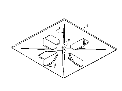
The rigid insulation corner fastener 1 has a
horizontal surface of various geometric ~hapes (round,
square, elliptical, polygonal, etc.) and dimension. The
horizontal surface can he formed with or without small
3tiffener ridges 2 to resist bending moment. On the
underside of the horizontal surface, vertical projections 4,
such as ears, le~, fins, etc. of various geometric shapes
protrude down at 90 degrees to the horizontal surface. The
invention requires these vertical projections to fit down
into the lineal (0, 90, 180, 270 degree) intersecting joint
pattern formed by the corners of adjacent rigid insulation
boards a3 shown in Figures 9 and 11.
At the center of the horizontal surface, an
adequate center pilot hole 3 i~ provided to facilitate top
insertion oP a nail~ screw, bolt, etc. 7 down into or through
tha substrate 6. Setting tight the nail, screw~ bolt, etc.
2~ draw3 the rigid insulatlon corner fastener to a co~pression
condition against the top ~urface of the insulation 5 and
secures the insulation fro~ upward or lateral movement.
For compari~on purpo~e~, existing technology for
securing insulation require~ three or four di~cs 8 as ~hown
in Figures 8 and l0 which deplct prior art device~.
1 307643
The rigid insulation corner fastener can be metal
or plastic. If made of metal it is sheared, press blanked
and formed. I~ made of plastic it is injection molded.
The metal used in metal fabrication of the rigid
insulation corner fastener would be sheet or roll stock, of
adequate gauge and stiffness (rigidity) to be formed into the
shape5 pattern or configuration required. The initial rough
workiDg dimension of the ~etal can be determined by shearing
sheet stock or preset by the width of roll coil stock. With
either sheet or coil stock, it is fed into a more precise
cutting and ~orming machine such as a punch press. A "Cut
and Form" die with male and female sections would impart the
desired shape, form or fini~h to the metal. The die would
cut the metal a-t the peripheral edge, cut the outline shape
of the vertical projections and punch out the center pilot
hole. The die would form (bend) the 90 degree downward
projections referred to as ears, fins, legs, etc. Any
reinforcing ridges or screw head recesses in the horizontal
surface of the rigid insulation corner fastener would also be
formed by the die.
Other methods o~ metal ~abrication, such as but not
limited to, a progre~sive die, drilling the center pilot
hole9 cutting by use of a metal shear or utilizing other
bending or shaping tools, are not precluded in the
~abrication of this invention.
,
Th~ plastic used in plastic ~abrication o~ the
rigid insulation corner fastener ~ould be adaptable to
injection molding. The plastic would be forced into a cavity
mold forming a rigid insulation corner fastener of the size
and shape determined by the void within the mold. Vertical
- ~ 3076~3
projections, referred to as ears, fins, legs, etc. uould be
formed as p~rt of the void within the cavity mold, as would
rein~orcing ridges, holes or other design (features)
criteria. The plastic, injection ~olded, rigid insulation
corner -fastener can be form-molded of one monolithic piece;
however, if any holeq voids or other design criteria are not
included in the mold configuration they could be accomplished
by other tools, heat, bending equip~ent etc.
The rigid in~ulation corner fa~tener can ~e u~ed to
secure insulation to various types o~ sub~trate sur~aces
(roof decks). The substrate ~ay be wood, metal, concrete
(regular or lightweight), existing membrane or other types of
sur~aces.
The rigid insulation corner ~astener is not placed
(insta]led) until after the rigid insulation i~ placed on the
substrate (deck). Roof insulation can be placed in ~everal
pattern~, the two mo~t common patterns are "Stack Bond" and
"Running Bond". Stack bond is typical o-~ the pattern used
for ~etting toilet room tile, where all edges of the
individual pieces run parallel to each other and ~orm
straight lines. The joint~ form the appearance of "Plus (~"
signs. Running bond pattern is typical of the accepted
pr~ctice ~or brick wall construction, where only the long
edgeo of the individual pieces run parallel to each other and
form straight lines. The short edge~ butt and ~orm straight
lines at 90 degree~ ~rom the mid-point of a previously
installed piece. The joints form ths appearance of upright
and inverted "T" shapes. For the following description the
running bond pattern will be the exemplar.
`` 1 3~7643
After placing the rigid insu:lation in the running
bond pattern, the installer will notice all the intersecting
corner~ o-f the insulation forming the "T" shape. Selecting
one rigid insulation corner fastener, either metal or
plastic, the installer will note the three vertical
projections referred to as ears, -fins, legs, etc. project-
down at 90 de~rees from the hori20ntal surface. The
in~taller will then place one rigid insulation corner
~astener at each "T" inter~ection formed by the corners of
the in~ulation boards. It is obvious that the installer will
not place the vertical projections up, since that would
impair the roofing ~embrane to be subsequently installed.
Rather, the installer would take the rigid insulation corner
~astener and place the vertical projections down into the
crack void, with the horizontal surPace restin~ on top of the
insulation boards. Then taking a nail, screw, bolt or other
holding devicel depending on the deck substrate, insert same
into the provided center pilot hole of the rigid insulation
corner fastener. After se`lecting the proper tool, hammer,
drill, screw-driver, socket wrench, or other, the in~taller
would drive, rotate, tighten, etc. until the holding device
pulled the rigid insulation corner fa~tener to a tight
compression condition on top of the in~ulation boards to be
secured. The installer would continue this installation
procedure until all corner inter~ection areas of the several
insulation boards were covered and secured by a rigid
insulation corner fastener.