Note : Les descriptions sont présentées dans la langue officielle dans laquelle elles ont été soumises.
SYRING13 PRESSURE CA]LIBR~TION RXl?ERENC~
Field of Invention
The present invention generally pertains to a pressure calibration
device, and specifically to a device for calibratin~ pressure transducers at rela-
tively low gauge pressuresI by producing a known reference pressure.
Background of the Invent on
Relatively inexpensive solid state pressure transducers are rou-
tinely used for monitoring the cardiov~cular pressure and other fluid pressures of
patients who are hospitalized or undergoing medical treatment and diagnostic
10 tests. The accuracy of these pressure monitoring devices is subject to change,
possibly producing substantial errors in the indicated pressure. ITI certain critical
procedures where the patient's physiologic~l state must be accurately monitored,errors in a pressure transducer conne~ted to monitor a vital body function may
become very significant, even life-threatening in their consequences.
Calibration of such pressure monitoring devices msy be accom-
plished by comparison against a reference standard to which the same fluid pres-sure is applied. Ideally, the pressure transducer under test should be calibrated at
a minimum of three reference points, including its full scale rated pressure, todetermine its accuracy and linearity. Although a more accurate reference stan-
20 dard such as an air piston gauge may be used, a digital readout pressure reference
standard is available for this purpose. The device is approximately the same size
as a hand calculator and weighs several pounds. This reference standard is de-
signed to supply a variable calibration pressure to a pressure transducer under
test. Adjustment of the calibration pressure is effected by turning a thumb wheel
25 to vary the fluid displacement of a piston in a cylinder.
Although relatively small, the above-described prior art pressure
transducer reference standard is too bulky to be conveniently carried on the
person of a nurse or medical technician. In addition, its cost makes it impractical
--2--
to equip each Individual having R need to check pressure monitors with the de-
vice. Unfortunately, experienee has shown that unless a reference standard is
readily at hand, pressure transducers used in critical medical applications are
unlikely to be cslibrated as often as should be. With the growing concern about
medical malpractice, it has become very important for hospitals, doctors and
health care personnel to take all reasonable steps to ensure the patient's well-being. Such reasonable steps would probably include fre~uently checking the
accuracy of pressure monitoring devices used to monitor critical bodily functions.
In consideration of these concerns, it is an object of the present
10 invention to provide a low cost, portable calibration reference, useful for cali-
brating pressure monitoring devices.
It is a further object to provide an easily adjusted calibration
pressure that may be readily input to the pressure monitoring transducer.
A still further object is to provide a known calibration reference
15 pressure with a compact device, sufficiently small and lightwelght to be carried
on the person of a user.
Yet a still further object is to provide a digital display on a cali-
bration reference standard, indicating the pressure of the fluid supplied to cali-
brate the pressure monitoring device.
These and other objects of the invention will be apparent from the
description of the preferred embodiment of the invention in relation to the
attached drawings.
Summary of the Invention
The present invention is directed to an apparatus useful for cali-
25 brating pressure sensing devices by supplying a fluid at a known pressure. The
apparatus comprises a plunger, adapted for use with a syringe having an output
port connected through a line in fluid communication with a de-/ice to be cali-
brated. The plunger, sized to slide snugly inside the syringe, is inserted therein,
and a force is applied to the outwardly extending end of the plunger by an opera-
30 tor to develop a desired calibration pressure. A calibration pressure less than
local atmospheric pressure is developed by pulling outwardly on the end of the
plunger. Alternatively, a calibration pressure in excess of local atmospheric
pressure may be developed by forcing the plunger inwardly of the syringe.
I'he plunger includes a hermetic seal disposed around its outer
35 circumference, adapted to engage the inner surface of the syringe. The seal,
preferably an "O" ring, reduces or eli`minates fluid leakage between these surfaces
as the plunger is moved inside the syringe. A pressure transducer is disposed
- ~ 3~;7~86
-3--
within the syringe, exposed to the fluid pressure developed by the operator-applied
force. The pressure transducer produces a signal proportional to the pressure
developed within the syringe and the attached line. Connected to the pressure
transducer inside the plunger are processor means. The processor means are
5 operative to drive a digital display that is also disposed within the plunger, on
which the calibration pressure developed by the operator is displayed. This cali-
bration pressure is communicated through the fluid line to the pre~sure monitoring
device being calibrsted, for comparison to its indicated pressure.
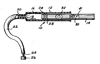
Brief Description of the Dr~win
FI~URE 1 illustrates a cutaway side view of a syringe, showin~
how a preferred embodiment of the present invention is fitted therein;
FIGURE 2 illustrates a plunger comprising the present invention in
longitudinal cross-sectional view;
FIGURE 3 is a schematic representation of a solid state pressure
transducer used in the plunger of the preferred embodiment;
FIGURE 4 shows the solid state pressure transducer of FlaURE 3
in a cross-sectional view;
FIGURE 5 is a functional block diagram of the electrical circuit
used in the preferred embodiment of the present invention; and
FIGURE 6 is a flowchart illustrating the logic of the control algo-
rithm used in providing a digital display of calibration pressure.
Description of the Preferred Embodiment
With reference to FIGURE I, a pressure calibrator constructed in
accordance with the present invention is generally denoted by reference
25 numeral I0. Pressure calibrator 10 includes a generally conventional plastic (or
glass) hypodermic syringe barrel 12 and a plunger I~ si~ed to fit snugly within the
internal bore 16 of the syringe barrel. When inserted into syringe barrel 12 as
shown in FIGURE I, the inwardly extending end of plunger 14 defines one end of achamber I8 containing a fluid. Normally this fluid comprises air, although liquids
30 and other gaseous fluids may be used.
An output port ~0 is defined by the end of syringe barrel 12, where
it necks down to a relatively small diameter cylindrical surface on which a hypo-
dermic needle would be fitted if the syringe were used conventionally. Instead,
one end of a length of tubing 22 is fitted over output port 20, and the other end is
35 attached to a reference pressure port 24 of a pressure monitoring device that is to
be calibrated, providing a fluid communication path between chamber 18 and the
pressure monitoring device 26.
J7~
--4--
Just as movement of the ~olid plastic or glass plunger normally
used with a hypodermic syrin~e is operative to change the volume within the
syrin~e, forcing fluid through an attached needle, movement of plunger 14 withinsyringe barrel 12 changes the volume of chamber 18. Furthermore, as the volume
of chamber 18 changes, the pressure of fluid within the chamber and tubing 22
changes proportionally. Whenever plunger 14 is partially withdrawn from the
internal bore 16 of syringe barrel 12, the volume of chamber 18 is increased, snd
the pressure of fluid within the chamber and within tubing 22 is reduced. Con-
versely, as a force applied to the end of plunger 14 (in alignment with its longitu-
0 dinal axis) causes it to move further into the internal bore 16 of the syringe
barrel, the volume of chamber I8 decreases, with a concomitant increase in
pressure of the fluid contained therein.
Two "O" rings 28 are fitted within grooves formed on the outer
surface of plunger 1~, providing a hermetic seal between the outer surface of the
lS plunger and the internal bore 16 of syringe barrel 12. "O" rings 28 substantially
eliminate leakage of fluid between these surfaces as plunger 14 is moved within
syringe basrel 12. It may also be possible to provide an adequate seal with onlyone "O" ring 28.
Disposed on the side of plunger 14 are a pushbutton switch 32 and a
digital display 30. Pushbutton switch 32 is centered in a depression within the
cylindrical surface of plunger 14, inset sufficiently so that the top of the push-
button does not contact the internal bore 16 of syringe barrel 12 when plunger 14
is inserted therein. Digital display 30 has 2 3/4 digits of resolution, i.e., it is
capable of displaying a reading in the range ~ 399.
Turning now to FIGURE 2, a cross-section of plunger 14 illustrates
details of the internal construction of the plunger. Plunger 14 comprises a cylin-
der 38 formed from plastic or a metal such as brass. Cylinder 38 is shorter and
approximately the same diameter as a conventional ball point pen, and is readilycarried on the person of a user, e.g., in a breast pocket oî a sh rt. A printed
30 circuit card 40 is disposed along the longitudinal axis of cylinder 38, centered
therein and extending diametrically across the cylinder. A plurality of electronic
components generally denoted by reference numeral 62 are mounted on printed
circuit board 40, including a microprocessor 54. Digital display 30 .s also mounted
upon printed circuit board 40, positioned immediately below a pla~tic window 41
35 that is fitted into an opening within cylinder 38. The window has substantially the
same radius of curvature as the e~ternal surface of the cylinder.
~3~
--5--
- A plug 64 is threaded into one end oY plunger 14. Plug 64 is remov-
able to provide access to a pair of button or disc-shaped lithium batteries 42,
which provide power for electronic components 62. Under normal intermittent
usage, lithium batteries 42 are expected to provide power îor the components 62
5 for up to five years; however, plug 64 may be removed so that the batteries can be
replaced or so that electronic components 62 may be serviced. A spring 58 is
connected to the adjacent end of printed circuit board 40, providing an electrical
connection between a conducting trace (not shown) on the printed circuit board
and the case of one of the batteries 42. In addition, spring 58 provides a biasing
10 force to ensure good electrical contact between the spring snd battery, and be-
tween the two batteries. The center of the other battery ~2 contacts a con-
ducting surface (not shown) that is also connected to the printed circuit board 40.
Pushbutton switch 32 includes a conducting surface 35 disposed
adjacent a pair of spaced apart electrical contacts 34 on printed circuit
5 board 40. Depression of the pushbutton completes the circuit between contacts 34
through conducting surface 35, energizing electronic components 62 as will be
described in greater ~detail hereinbelow. Pushbutton switch 32 also includes a
helical spring 44 to bias surface 35 away from contacts 34; a flange 36 formed
around the perimeter of the pushbutton abuts the interior surface of cylinder 38,
20 serving to retain the pushbutton inside cylinder 38.
The end of cylinder 38 that is inserted into syringe barrel 12 ~on
the left as shown in FIGI~RE 2) defines a port 60 through which pressurized fluid is
applied to a pressure transducer 56 mounted inside the cylinder, adjacent
port 60. Details of pressure transducer 56 are shown in FIGURES 3 and 4. The
25 pressure transducer used in the preferred embodiment is a conventional piezo-resistive silicon sensor, including P-type regions comprising sensing resistors 70
and 71, disposed in an N-type silicon wafer 72. The center of the N-type siliconwafer 72 is a relatively thin silicon d;aphragm 74. Layers of silicon oxide 76
insulate the surfaces of silicon wafer 72. During manufacture, its bottom surface
30 is joined to a plate 82 (while within a vacuum environment~, forming a vacuumchamber 78 between plate 82 and the center silicon diaphragm 74 of the wafer.
The P-type regions comprising sensing resistors 70 and 71 are
disposed in silicon wafer 72 adjacent the top sur~ace of silicon diaphragm 74,
around the edge of vacuum chamber 78, and are connected by conductors 80 in a
35 standard Wheatstone bridge circuit. Application of fluid pressure to silicon dia-
phragm 74 causes it to deflect, changing the relative res5stances of the sensingresistors 70 and 71. When exposed to a vacuum, no pressure is applied to the
~3(~7~86
--6--
silicon diaphragm, and the resistance of resistors 70 and 71 are substantially equal
since the Wheatstone bridge is in a balanced condition. If a voltage is applied to
nodes 84 at diagonally opposite corners of the bridge, the potential difference
between nodes 82 at the other two corners is then approximately zero. Con-
S versely, when the center of s;licon diaphragm 74 is deflected by an applied fluidpressure, the potential difference between nodes û2 changes in direct proportion
to the pressure, the resistance of sensiag resistors 70 increasing, and the resist-
ance of sensing resistors 71 decreasing by equal amounts, creating an imbalancedcondition of the Wheatstone bridge. With voltage applied to nodes 84, pressure
I0 transducer 56 then provides an output voltage between nodes 82 that is propor-
tional to the pressure applied to center silicon diaphragm 7~ of the Sransducer.Those skilled in the art ~/ill appreciate that other types of pressure
transducers might be used in this application. For example, a transducer respond-
ing to pressure by changing capacitance, thus varying the resonant frequency of a
5 connected circuit, would be suitable. Any such pres`sure transducer used should
have a rated accuracy at least eguivalent to that of the pressure monitoring
devices likely to be calibrated, and should produce a voltage, current9 or some
other physical parameter that changes as a function of the applied pressure, in the
desired range. In the preferred embodiment, pressure transducer 5~ has a rated
20 accuracy of ~1% of the applied pressure and is rated to measure pressures of at
le~st + 400 mm. of mercury.
Referring now to FIGURE 5, a block diagram shows the relation-
ship between the various electronic components 62 of pressure calibrator 10.
Power for the electronic components used in the circuit represented in FIGURE S
25 is supplied by batteries 42, connected to ground and to a power switching circuit
100, by a conductor 98. Power switchlng circuit 100 controls the application of
DC voltage to each of the other elements of the pressure calibrator in response to
a signal provided over a conductor 9~ from microprocessor 54. In the preferred
embodiment, an internal timer within microprocessor S4 resets and counts down
30 for a predetermined interval each time pushbutton switch 32 is depressed, so that
battery power is applied to the electronic components of pressure calibrator 10
only for 90 seconds, thereby ensuring that batteries 42 are not run-down by some-
one inadvertently leaving the device energized for an extended period of time. ~transistor switch (not shown) or other type of electronic switch may be used to
35 carry out the functions of power switching circuit 100, as will be apparent to
those of ordinary skill in the art. Conductor 98 also conveys DC power from
batteries 42 to a start circuit 110. Start circuit 110 includes pushbutton switch
~3~i7~l36
,
-7--
32, which when depressed, applies DC voltage through conductor 112 to reset the
internal counter within microprocessor 54. In response to the signal from micro-processor 54 initiating the 90 second timed period, DC power is applied via con-ductor 102 to a display circuit 128, microprocessor 54, a low battery detect cir-
5 cuit 104 anà to pressure transducer 56.
Low battery detect circ-uit 104 is operative to compare the DC
voltsge on conductor 102 to a reference voltage derived from a battery check
signal supplied by microprocessor 54 to the low battery detect circuit over con-ductor 108. The battery check signal is clamped at approximately 0.6 volts DC
10 using a diode (not shown) and compared to a voltage obtained b~r a divider circuit
(not sho-qn) from the battery power supply. Such low battery detect circuits arewell known to those of ordinary skill in the art. The result of the battery voltage
check performed by the low battery detect circuit 104 is returned to micro-
processor 54 via conductor 106.
A microprocessor oscillator 114 is provided for use as a time base
by microprocessor 54. In the preferred embodiment, microprocessor oscillator 114s;mply comprises an RC circuit. Alternatively, a cryst~l osclllator could be used;
however, the accuracy of a crystal is not required in this application. The timebase- signal provided by microprocessor oscillator 114 is input to microprocessor 54
20 through a conductor 118.
- A plurality of data lines 12~ connect microprocessor 54 to a display
circuit I28, comprising the 2 3/4 digital display 30 and an appropriate driver chip
(not separately shown). Data provided via data lines 126 are used by the displaydriver to energize selected digits of digital display 30, indicating the pressure
25 sensed by pressure transducer 56 as will be explained hereinbelow.
An optional unit reading selector 132, comprising a jumper wire
~not shown~ or other suitable switching device is provided on printed circuit board
40 (FIGURE 2) to change the ~mits of pressure indicated by digital display 30 from
the "normal units," millimeters of mercury, to inches of water column (or some
30 other units of pressure). Unit readin~ selector 132 provides a means for selecting
the "optional" units of pressure by grounding an input port of rnicroprocessor 54
through conductor 130. It is not contemplated that a change in pressure units
should be readily available to an operator of pressure calibrator 10.
The heart of the pressure calibrator is the pressure transducer 56.
35 As explained above, it produces a DC voltage proportional to an applied fluidpressure. This voltage is output via conductor 118 to analog-to-di~ital converter
120. Although various analog-to-digital converter chips are commercially avail-
~3~75a8~i
-8--
able, in the preferred embodiment, analog-to-digital converter 120 implements a
dusl slope integrator technique in which an internal counter within microprocessor
54 accumulates counts in a register for a period of time proportional to the volt-
age output by pressure transducer 56. Initiation of the analog-to-digital conver-
5 sion process begins with a signal output by microprocessor 54 over conductor 122to analog-to-digital converter 120 and terminates in response to a signal ~roman~log-to-digital converter 120 input to microprocessor 54 via conductor 124.
Other techniques and commercially available A-D converter integrated circuits
suitable for providing 2 3/4 digit resolution and 1% a~curacy might also be used10 for thls application, as will be apparent to those of ordinary skill in the art.
Microprocessor 54 preferably comprises a National Semiconductor
Corporation model COP 411-C CMO~ microcontroller. It i9 anticipated that
similar microprocessors may be used for this application, preferably those with
relatively low power consumption, to ensure extended battery life. Included
15 within microprocessor 54 is a read only memory (ROM), in which a series of
mach;ne language instructions are stored for carrying out each of the steps imple-
mented by the microprocessor, including: checking the battery condition, carrying
out the analog-to-digital conversion process to digitize the pressure responsivesignal produced by the pressure transducer, converting the digitized signal to a20 pressure, applying ~he selected units to the pressure messured by pressure trans-
ducer 56, and displaying the pressure on digital display 30. Microprocessor 54 also
includes random access memory (RAM) for temporarily storing variables used in
carrying out tbese fuwtions.
A flowchart illustrating the algorithm implemented by micro-
25 processor 54 is shown in FIGURE 6. Beginning with block 140, the control logic"starts" with the depression of pushbutton switch 32, initiating the 90 second
internal countdown timer. In block 142, microprocessor 54 implements the ana-
log-to-digital conversion of the signal output from the pressure transducer via
conductor 122 (FIGURE 5). Initially, pressure transducer 56 is exposed to atmos-
30 pheric pressure so that microprocessor 54 can establish a Zero Pressure reading,as indicated in block 144.
In block 146, the analog-to-digital conversion process is again
implemented, aftPr the pressure applied to pressure transducer 56 has changed
from the initial atmospheric pressure as checked in block 148. The value of the
35 variable, "Pressure," is updated to reflect the new reading in block 150. Following
the step in block 150, (or i~ the result oî the check made in block 148 is negative),
in block 152, microprocessor 56 determines if the alternate units switch has been
13~7~
g
set, and if so, in block 154, converts the value for Pressure to ~n equivalent value
in the alternate units. This conversion is done by multiplying Pressure by the
appropriate conversion factor. Of course, if the alternate unit switch has not
been set, block 1S4 is skipped, control logic proceeding directly to block 156. In
5 block 156, the condition of the batteries 42 is checked by low battery detect
circuit 104, in response to a signal produced by microprocessor 54.
Finally, in block 158~ microprocessor 54 outputs the pressure
reading to display eircuit 128 via data lines 126 causing digital display 30 to
indicate the pressure in the selected units, and to indicate the current battery10 status. Although not shown in the flow chart, should the pressure 0xceed the
maximum rated range for pressure calibrator 10 (~399 mm of mercury) in block
158, microprocessor 54 may optionally cause digital display 30 to blink on and of f
while displaying the numbers 399, or alternatively may display the letters "DP"
(defective pressure), or other symbols indicating a fault condition. During the 90
15 second period following initiation of the pressure measurement, microprocessor 54
repeats steps 146 through 158, terminating at block 160 when the 90 second period
has expired.
In using pressure calibrator 109 the operator depresses pushbutton
32 on plunger 14 prior to inserting it within syringe barrel 12, permitting micro-
20 processor 5~ to auto~:ero so that digital display 30 reads 0 mm of mercury when
initially exposed to atmospheric pressure. Thereafter, plunger 14 is immediatelyinserted to its full extent within syringe barrel 12 and tubing 22 is connected to
output port 20. Plunger 14 is partially withdrswn ~rom syringe barrel 12, develop-
ing a pressure within chamber 18 that is less than local atmospheric pressure.
25 This subatmospheric pressure is communicated via tubing 22 to the pressure
monitoring device 26. Plunger 14 is displaced within syringe barrel 12 until thedesired calibration pressure is indicated on digital display 30. This ealibration
pressure is then compared against the pressure indicated by pressure monitoring
device 26.
Plunger 14 may be twisted within syringe barrel 12 to make small
incremental changes in the indicated pressure. lt has been found thst static
friction between "O" rings 28 and the internal bore 16 of syringe barrel 12 is
sufficient to hold plunger 14 in place, once a desired calibration pressure is
achieved by the operator. The calibration pressure developed in this manner is
35 below ambient or local atmospheric pressure, as is conventional for calibrating a
conventional pressure monitoring device 28. Port 24 on pressure monitoring
device 26 corresponds to a normally vented reference pressure port. When a
~IL3~7~
-10-
subatmospheric calibration pressure is applied to reference port 24 while the port
(not shown) that is normally exposed to a monitored fluid pressure is exposed toatmospheric pressure, pressure monitoring device 26 should indicate a pressure
equal but opposite in siKn to the pressure shown on digital display 30. Comparison
of the display 32 on pressure calibrator lO with the pressure indicated by pressure
monitoring device 26 determines the error of the device.
Pressure calibrator 10 may also be used to generate cnlibration
pressures that are greater than local atmospheric pressure. As before, pushbutton
switch 32 is depressed prior to inserting plunger 14 into syringe barrel 12, auto
zeroing the regding. Plunger 14 is inserted into syrinee barrel 12 until a seal is
obtained between the "O" rings 28 and the syringe bore 16, and tubing 22 is con-nected to output port 20. Sufficient force is then applied against the end of
plunger 14 (directed along its longitudinal axis) to obtain a desired ca}ibration
pressure indication on d;gital display 30 as the plunger slides into the syringebarrel. Using this technique, a calibration pressure in excess of local atmospheric
pressure is developed within chamber 18 and applied to the port (not shown) of
pressure monitoring device 26 that is normally used to monitor pressure. The
latter technique is also useful in calibrating pressure monitoring devices that do
not include a readily accessible reference port 24.
While the present invention has been described with respect to a
preferred embodiment, those skilled in the art will understand that various
changes and modifications thereto may be made within the scope oï the claims
that follow hereinbelow.