Sélection de la langue

Search

Sommaire du brevet 1308009 

Énoncé de désistement de responsabilité concernant l'information provenant de tiers

Une partie des informations de ce site Web a été fournie par des sources externes. Le gouvernement du Canada n'assume aucune responsabilité concernant la précision, l'actualité ou la fiabilité des informations fournies par les sources externes. Les utilisateurs qui désirent employer cette information devraient consulter directement la source des informations. Le contenu fourni par les sources externes n'est pas assujetti aux exigences sur les langues officielles, la protection des renseignements personnels et l'accessibilité.

Disponibilité de l'Abrégé et des Revendications

L'apparition de différences dans le texte et l'image des Revendications et de l'Abrégé dépend du moment auquel le document est publié. Les textes des Revendications et de l'Abrégé sont affichés :

  • lorsque la demande peut être examinée par le public;
  • lorsque le brevet est émis (délivrance).
(12) Brevet: (11) CA 1308009
(21) Numéro de la demande: 1308009
(54) Titre français: EXPANSION DE TUBES METALLIQUES, PAR METHODE EXPLOSIVE
(54) Titre anglais: EXPLOSIVE EXPANSION OF METAL TUBES
Statut: Périmé et au-delà du délai pour l’annulation
Données bibliographiques
(51) Classification internationale des brevets (CIB):
  • B21D 26/08 (2006.01)
  • B23K 20/08 (2006.01)
  • F42D 3/00 (2006.01)
(72) Inventeurs :
  • HARDWICK, ROY (Royaume-Uni)
(73) Titulaires :
  • IMPERIAL CHEMICAL INDUSTRIES PLC
(71) Demandeurs :
  • IMPERIAL CHEMICAL INDUSTRIES PLC (Royaume-Uni)
(74) Agent: C. BRIAN BARLOWBARLOW, C. BRIAN
(74) Co-agent:
(45) Délivré: 1992-09-29
(22) Date de dépôt: 1988-08-30
Licence disponible: S.O.
Cédé au domaine public: S.O.
(25) Langue des documents déposés: Anglais

Traité de coopération en matière de brevets (PCT): Non

(30) Données de priorité de la demande:
Numéro de la demande Pays / territoire Date
8721985 (Royaume-Uni) 1987-09-18

Abrégés

Abrégé anglais


34466
ABSTRACT
"Explosive Expansion of Metal Tubes"
In a method of explosively expanding a tubular metal
component into engagement with a surrounding metal component,
an explosive charge is disposed axially and fired in an
insert comprising a hollow cylindrical container fitting
closely within the portion of the tubular metal component to
be expanded and having charge holding means, for example, an
axial pocket, to accommodate the explosive charge, the
container being filled with a shock wave-transmitting liquid.
Compared with solid inserts, the novel hollow insert is
cheaper and requires a smaller explosive charge for a given
operation. The method is especially advantageous for
expanding large diameter tubes.

Revendications

Note : Les revendications sont présentées dans la langue officielle dans laquelle elles ont été soumises.


34466
CLAIMS
1. A method of explosively expanding a tubular metal
component into engagement with a surrounding metal component
wherein an explosive charge is disposed axially and fired
within a shock wave-transmitting insert located within the
portion of the tubular metal component to be expanded,
characterised in that
the shock wave-transmitting insert comprises a hollow
cylindrical container fitting closely within the portion of
the tubular metal component to be expanded and having
charge-holding means to accommodate the explosive charge and
locate it axially within the container, the container being
filled with a shock wave-transmitting liquid.
2. A shock wave-transmitting insert for holding an
explosive charge axially within a tubular metal element to
be expanded and to transmit the shock wave from the said
charge to the said tubular metal element when the charge is
fired, characterised in that
the said insert comprises a hollow cylindrical container
and charge-holding means to accommodate an explosive charge
and locate it axially within the container, said container
being adapted in use to be filled with a shock wave-
transmitting liquid.
3. An insert as claimed in Claim 2 wherein the said
charge-holding means comprises a pocket extending axially
into the container from an end wall of the container.
4. An insert as claimed in Claim 2 wherein the said
hollow cylindrical container is fabricated from synthetic
plastics material.

7
5. An insert as claimed in Claim 4 wherein the hollow
cylindrical container is fabricated from polyethylene.
6. An insert as claimed in Claim 2 wherein the hollow
cylindrical container is a blow moulded container.
7. An insert as claimed in Claim 2 wherein the hollow
cylindrical container comprises
an outer open-ended cylindrical shell and a lid for
closing the open end of said shell, said lid having a pocket
formed therein and adapted to hold the explosive charge.
8. An insert as claimed in Claim 7 wherein the shell
and/or the lid is spin- moulded thermoplastics material.
9. An insert as claimed in Claim 7 wherein the outer
shell is formed with an external flange at its open end,
said flange being operative to abut an end of a tubular
metal element which is to be expanded thereby effecting
positive axial location of the insert in said tubular
element.
10. An insert as claimed in Claim 7 comprising sealing
means to seal the joint between said lid and said shell to
prevent leakage of liquid from the interior of the insert.
11. An insert as claimed in Claim 10 wherein the sealing
means comprises at least two circumferential inward
projections on the wall of the outer shell which engage the
periphery of the lid.

Description

Note : Les descriptions sont présentées dans la langue officielle dans laquelle elles ont été soumises.

3~
34~66
This inven~ion r~lates to a method o~ ~xplosively expanding
a metal tube into engagement with a surrounding m~tal
componen~ and to a shock wav~-transmitting insert for use in
5 the said method.
The expansion of metal tubes into bor~s in surrounding metal
components is well known and is employed, for ex~mple, to
expand tubes into tube~lates in the manufacture o~ boilers
and heat exchangers. The joint formed between ~he tube and
10 the surrounding component may be a me~hanical or
metallur~ically bonded ~oint. In the expansion pro~ess an
explosive char~e is initially located and exploded within
the tube bore at a po~i lon coinc~dent. with a surrounding
compon~nt. Tn one arrangement whi~h i.s favoured for small
15 diameter tube~`the explosive charge i9~ initially disposed
axially within a thick-walled tubular ~hock wave-
transmlttin~ compo~snt which is ~en~rally termed an ins2rt.
Usually th~ in~Qr~ is moulded ~rom a m~teri~l such as
poly~hylen~, rubb~r or wax. ~efor~ i~ is exploded, the
20 explo~iv~ charg~ i9 loc:at~d in the insert to lie
syn~tric~lly a~ th~ axi~ of the tub~3 bore. In an
alternativ~ arrangement which i~ adv~ntng~ous for larger
diameter ~ubes th~ explosive ch~rg2 is ini~i~lly disposed in
the ~orm of an annular charge in clos~ proximity to th~ tube
25 bore. The annular charge is more e~onomical for larg~ tubes
sinc~ the larg~ in~exts, ne~d~d for axially dispos~d charges
in large ~iameter tubes are ex~es ively 0xpen~ive due to the
large volume o~ ma~erial required and the long mc~ulding time

~L3(~8
required in their manufacture in ord~r to avoid cavitation.
Moreover, heavier axial char~es are required since the
thicker wall of the insert significantly attenuates the
shock wave and the attenuation must be compensated by an
5 increased charge. However, a serious disadvan~a~e of an
annular charge is that it must be initiated by a complex
initiation system in order to obtain simultan~ous initiation
around the entire circumference,since single-poin~
initiation give rise to ~ube damage when the separate
10 diverging detonation ron~s emanating from th~ point of
initiation and travelling around the tube bore circumference
meet a~ a position diametrically opposite the initiation
point (i.e. the "Dautriche" effect).
It is an object of this inven~ion to provi~e an improved
15 method of explosively expanding a metal tub~ into a
surrounding metal component by means of an explosive charge
axially disposed within th~ tube, the method being suitable
for expanding large diam~ter tub~. In the improved method
the thick-walled moulded insert u~ed with axially disposed
20 charges is replaced b~ a liquid ~illed shell which is formed
to a~commodate the axial charge and ~o fit closely in the
bo~ of the me~al tube. The hollow thin-walled ins~x~ is
cheap~r to mak~ and the use o~ uld a~ the principal m~ans
of ~ransmitting th~ radial ~hock wa~ significantly reduces
25 the a~tenuation of the shock w ve by comparison with solid
ma~erials thus reducing ~h@ amo~nt of explosive charge
xequir~d for a given opera~ion.
Thus in accordaAco with the invention a method of
explosively expanding a tubular m~t~l component into
30 engagemen~ with a surrou~ding metal compon~nt wherein an
explosive charge is dispo~ed axially and fired within a
shock wave transmi~ting insert located within the portion of
the tubular metal component to be expanded, is characterised

~3~
ir, that the shock wave transmitting insert comprises a
hollow cylindrical container fitting clo~ely within the
portion of the tubular metal component to be expanded and
having charge-holding ~eans to accommodate the explosive
harge and locate it axially within the container, the
container being filled with a shock wave-transmitting
liquid, for example water.
l'he invention also includes a shock wave-transmitting insert
for holdin~ an explosive charge axially within a tubular
10 metal element to'be expanded and to transmit the shock wave
from the charge to the tubular met~l element when the charge
i5 fired, the insert comprising a hollow cylindrical
container and oharge-holding means to accommodate an
explosive charge and locate it a~ially within the container, `
15 and the container being adapted in use to be filled with a
shock wave- transmitting liquid.
rhe charge-holding means conveniently comprises a pocket
extending axially into the container from an end-wall of the
container.
20 The hollow cylindrical container i5 preferably fabricated
from synthetic plastics material for example, polyethylene.
It may be blow-moulded but a preferred form of container
comprises an outer open-ended cylindrical shell and a lid
for closing the open end of the shell, the lid having a
25 pocket formed therein and adapted to hold the explosive
charge. The shell and~or the lid may, for example, be
spin~moulded thermoplastics material such as polyethylene.
l'he outer shell of the preferred container is advantageously
formed with an external flange at its open endl the flange
being operative to abut an end of the tubular metal element

l3~soas
whi~h is to be expanded thereby e~fecting positive axial
location of the insert in the tubular element.
The joint between the lid and the chell is pre~erably sealed
to prevent leakag~ of liquid from the intexior of the
5 insert, suitable sealing means including at least two
circumferential inward projections on the wall of the outer
shell, which pro~eotions en~age th~ periphery of the lid.
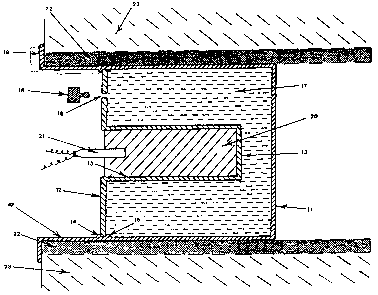
The invention is further illustrated by the preferred
embodiment which is hereinafter d~scrib~d with reference to
10 the aceompanying drawing which shows in longitudinal medial
cross-section an insert of t-he invention in position for
expanding a metal tube into engagement with a tube plate.
As shown in the drawing the in ert 10 comprises an
open-ended cylindrical container 11 and a lid 12, the
15 container and lid both being fabricated from moulded
polyethylene. The lid has an axi~l tubular pocket 13 formed
therein and is held in watertight enga~ement wi~h the
container 11 by in~erna} cir~umferential pro~ections 14 and
15 which grip ~he peripheral edgo of the lid. An aperture
20 16 is formed in the lid 12 through which the interior of the
in~ert 10 may be filled with water 17 or excess water can be
dra~ned when th~ lid is lower~d into position under wa~er in
contai~or 11. A clo~ure plug 18 i~ provided to close the
apertur~ 16 to prevent wa~er loss ~rom th~ insert. The
25 contain~r 11 i~ form~d wi~h an ex~ernal ~langa 19 at its
op~n end. The pocket 13 is ~illed with a plastic explosive
charge 20. For firing the exploslY~ ~hargs 20 an electric
detonator 21 is inserted into the outor end of th~ charge.
In the tube expansion operation an end portion of a metal
30 tube 22 is placed in an ap~rture of an outer metal component
23 and the water-~illed insert 10 ls in~rted in~o the tube

22 until the flang~ 19 abuts the tube ~nd. When the char~e
20 explodes the tube 22 is expand0d into en~a~ement with the
outer component 2 3 .

Dessin représentatif
Une figure unique qui représente un dessin illustrant l'invention.
États administratifs

2024-08-01 : Dans le cadre de la transition vers les Brevets de nouvelle génération (BNG), la base de données sur les brevets canadiens (BDBC) contient désormais un Historique d'événement plus détaillé, qui reproduit le Journal des événements de notre nouvelle solution interne.

Veuillez noter que les événements débutant par « Inactive : » se réfèrent à des événements qui ne sont plus utilisés dans notre nouvelle solution interne.

Pour une meilleure compréhension de l'état de la demande ou brevet qui figure sur cette page, la rubrique Mise en garde , et les descriptions de Brevet , Historique d'événement , Taxes périodiques et Historique des paiements devraient être consultées.

Historique d'événement

Description Date
Inactive : CIB de MCD 2006-03-11
Le délai pour l'annulation est expiré 1997-09-29
Lettre envoyée 1996-09-30
Accordé par délivrance 1992-09-29

Historique d'abandonnement

Il n'y a pas d'historique d'abandonnement

Titulaires au dossier

Les titulaires actuels et antérieures au dossier sont affichés en ordre alphabétique.

Titulaires actuels au dossier
IMPERIAL CHEMICAL INDUSTRIES PLC
Titulaires antérieures au dossier
ROY HARDWICK
Les propriétaires antérieurs qui ne figurent pas dans la liste des « Propriétaires au dossier » apparaîtront dans d'autres documents au dossier.
Documents

Pour visionner les fichiers sélectionnés, entrer le code reCAPTCHA :


Pour visualiser une image, cliquer sur un lien dans la colonne description du document. Pour télécharger l'image (les images), cliquer l'une ou plusieurs cases à cocher dans la première colonne et ensuite cliquer sur le bouton "Télécharger sélection en format PDF (archive Zip)" ou le bouton "Télécharger sélection (en un fichier PDF fusionné)".

Liste des documents de brevet publiés et non publiés sur la BDBC .

Si vous avez des difficultés à accéder au contenu, veuillez communiquer avec le Centre de services à la clientèle au 1-866-997-1936, ou envoyer un courriel au Centre de service à la clientèle de l'OPIC.


Description du
Document 
Date
(aaaa-mm-jj) 
Nombre de pages   Taille de l'image (Ko) 
Page couverture 1993-11-11 1 14
Revendications 1993-11-11 2 55
Abrégé 1993-11-11 1 19
Dessins 1993-11-11 1 61
Description 1993-11-11 5 184
Dessin représentatif 2001-07-24 1 40
Taxes 1995-09-06 1 34
Taxes 1994-08-08 1 268