Note : Les descriptions sont présentées dans la langue officielle dans laquelle elles ont été soumises.
` 1 3~637
-- 1 --
This invention relates to liquid handling
systems, and to apparatus for the analysis of fluid
samples, and has particular application to apparatus for
the analysis of constit~ents of biological fluids such
as blood
Clinical analyzers are useful in performing a
variety of analyses, including kinetic and endpoint
`~ analyses, by techniques such as absorption, light
scattering, and/or fluorescence. Many chemical analyses
must be conducted at controlled and stable temperatures
as the involved chemical reactions are temperature
sensitive. In conventional clinical analysis systems,
for example, raw or dilute sample is mixed with one or
more reactants for analysis, and the resulting mixture
is maintained in an incubator region to bring the
mixture to the desired analysis temperature, for
example, 37C, a temperature substantially higher than
the temperature at which sample and reagent ~aterials
are u~ually stored. Clinical analyzers of the
centrifugal type, in general~ utilize a multicuvette
rotor assembly which has a centrifugal array of spaced
elongated radially extending cuvettes, each of which has
an inner chamber for initially holding a first reactant
which is ~req~ently a sample of blood or other
biological fluid, and an outer chamber for initally
holding one or more different reactants. The two
chambers are separated by divider structure, and the
reactants are transferred by centrifugal force to an
analysis region at the outer end of the cuvette for
mixing and reaction and subsequent analysis. Small
quantities of sample (2 - 20 microliters) typically are
loaded into the inner chambers and reactants in
quantities of up to about 200 microliters are loaded
`` I 3(3'1637
60412-2230
in~o the outer chambers. After loading, each rotor is
conventionally incubated to equilibrate the rotor and the
reactants in its several cuve~tes to analysis temperature, and
after such incubation the contents of the xotor are analyzed.
In a typical analysis sequence, the rotor assembly is first
spun at 100 rpm, then accelerated to about 4000 rpm for about
one second for transferring the reactants from the inner
chamber, then braked for mixing the sample and reactants, and
then brought up to an analysis speed (typically 500 - 1000 rpm)
for analysis.
Such analyzers are commonly used for the analysis of
biological fluids such as blood, blood plasma or serum
components, and perform absorbance mode analyses Eor glucose,
cholesterol, creatinine, total protein, calcium, phosphorous,
enzymes, and the like; and fluorescence or light scattering
mode analyses for glucose, bile acids, phenytoin, pheophylline~
gentamycin and the like.
In accordance with one aspect of the invention, there
is provided an analysis sy~tem which has a first re~ion in
which sample materials are stored at an appropriate storage
temperature and a second region which is malntained at a
controlled and stabillzed temperature preferably higher than
the temperature of the first region. An analysis cuvette is in
the second region, and transfer mechanism is provided for
transferring a quantity of sample material from the first
region ~or loading into the analysis cuvette in the second
region. The transfer mechanism includes a liquid handling
probe that is mounted on a probe transport carriage, and a
drive for moving the transport carriage between the first and
second regions. The transport carriage includes a storage
chamber connected to the liquid handling probe, thermal energy
~{~
1 ~ rJ ù 6 ~ i~ 604l2-2230
supplying means in heat exchange relation with the storage
chamber, and thermal sensor means carried by the transport
carriage. Means responsive to the thermal sensor supplies
thermal energy to the thermal energy supplying means preferably
to maintain the storage chamber at substantially the same
temperature as the second region. Preferably, liquid sensor
means of suitable kype such as optical, conductive or
capacitive type is carried by the transport carriage for
sensing the presence of liquid in the region between the tip of
the probe and the storage chamber. Liquid metering means is
connected to the transport carriage, and control mean.~ is
provided for opera~ing the drive and metering means to draw a
predetermined quantity of sample material for analysis in~o the
probe and the stora~e chamher and to deliver the predetermined
quantity to the analysis cuvette in the second region in
temperature equilibrated condition.
In preferred embodiments, the transport carriage
includes a thermal mass ln the form of a metal cantilever arm
with the liquid handling probe fixedly mounted at one end
thereof, the temperature sensor embedded in the metal arm and
the thermal energy supplying means including heating means
distributed along the lenyth of the cantilever arm in lntimate
thermal trans~er relationship therewith. The storage chamber
is an elongated tubular conduit embedded in the metal arm in
coil form.
In a particular embodiment, sample and reagent
materials are stored in the first region, two probes are
mounted on the carriage~ the transport carriage includes two
storage chambers, one connected to each probe, and the control
means operates drive and metering means to draw predetermined
quantities of sample and reagent materials through the probes
-.~
1 3''J~37
60412-2230
and into the storage chambers and deliver the predetermined
quantities of sample and reagent materials to an analysis
cuvette in the second region in temperature equilibrated
condition. A plurality of analysis cuvettes are in the second
region, together with an analysis station and a transport
mechanism for transporting analysis cuvette~ sequentially to
the loading statlon where the cuvettes are loaded with sample
and reayent materials and then to the analysis station ~or
photometric analysis of the mlxture of sample and reagent
materials.
The analysis system of the invention may be
summarized, according to another aspect, as an analysis system
comprising
a flrst region in which sample materials are adapted to be
stored at an appropriate storage temperature,
a second region in which an analysis cuvette is adapted to
be disposed at an appropriake analysis temperature,
transfer mechanism for trans~erring a quantity of sample
materlal from said first region for loading into said analysis
cuvette in said second region,
sald transfer mechanism including an elongated liquid
handling probe tube,
a probe transport carriage on which said liquid handling
prohe is mounted, said carriage including a through channel for
receiving said probe tube and clamping means that permits the
axial position of said elongated probe tube in said carriage to
be axially adjusted~
a drive for moving said transport carriage between said
first and second regions,
liquid metexing means connected to saicl transport
carrlage, and
1 3~ j~37
60412-2230
control means fo} op~ra~ing ~aid driv~ and metering means
to draw a predetermined quantity of sample material for
analysis into said probe tube and to deliver æaid predetermined
quantity to said analysis cuvet~e in said second region.
In accordance with another aspect, the liquid
handling probe is a metal tube that is secured in the transport
carriage in a through channel that includes a threaded portion
and a tapered shoulder at one end of the threaded portion.
Clamping means .includes a clampiny member tha~ has a threaded
body and a passage axially extending through the threaded bo~y
that is defined in part by a circumferential array of axially
extending iinger portions in the threaded body~ each ~inger
portion having a tapered surface at one end thereof. When the
clamping member is ~hreadedly secured in the through passage
with the metal tube extending through the axially extending
passage in the clamping member body, the tapered end surfaces
of the finger portions engage the tapered shoulder and cam the
finger portions inwarclly to clamp the metal tube in the support
member. This arrangement facilitates individual adjustment of
each probe to position the probe tips in precise aligned
relation.
4a
~,
1 3~,~637
-- 5
In accordance with another aspect of the
invention, a liquid sensor system is provided that
includes a tubular member of dielectric material with
electrically conductive plate elements on opposite sides
3 of the tubular member to form an electrical capacitor of
capacitance value that varies as a function of the fluid
in the tube. In a particular embodiment, the tubular
member is connected in a series flow path between a
probe tip and a storage chamber in a transport
carriage. Means for monitoring the capacitance value to
provide an indication of the nature of the fluid in the
probe and storage chamber includes means for cyclically
charging and dischargi~g the capacitor and monitoring
the charge (or discharge) rate of the capacitor to
provide an indication of the type of fluid in the
tubular member.
In preferred embodiments, the tubular member is
of cylindrical configuration and the capacitor plate
elements are elongated electrodes that are plated on
opposite sides of the tubular member, each electrode
having an angular extent of about 90. A variable
frequency oscillator is coupled to a capacitor charge
control circuit for repetitively charging and
discharging the capacitor, and means are provided for
adjusti~g the frequency of the oscillator so that
particular fluids may be identified as a function of the
rate of charge (or discharge) of the capacitor which in
turn is a function of the dielectric (and/or
conductiVitY) characteristics of the fluid in the
tube. The sensor tube may be straight or of other
shape and may be used in a variety of liquid sensing
applicationS. In a particular embodiment, two such
sensing units are mounted on the cantilever arm of the
transport carriage between probe inlets and storage
,~,,"~ . ,", , ~,,. ; ,
1 ;~C3637
6 --
chambers. In that embodiment, a multicuvette analysis
assembly of long thermal time constant material is
employed, and small (less than one cubic centimeter),
precise, operator-selected quantities of sample and
reagent liquids are concurrently transferred (via the
storage chambers) from supply containers to the analysis
cuvette in a time interval of abou~ one second, that
time interval being sufficient for those sample and
reagent materials to be equilibrated to the analysis
temperature so that substantially no further thermal
equilibration interval is needed. In that embodiment,
the clinical analyzer is of the centrifugal type and
uses a multicuvette rotor which has a circumferential
array of spaced elongated radially extending plural
chamber cuvettes, each of which has an inner chamber for
initially holding a first reactant (frequently a sample
of blood or other biological fluid), and an outer
chamber for initially holding one or more dif~erent
reactants. After the rotor is loaded, the reactants are
transferred by centrifugal force to an analysis region
at the outer end of the cuvette for mixing and reaction
and subsequent analysis by photometric or other
appropriate analysis techni~ue.
Preferred embodiments of the invention provide
a system in whi~h sample and reagent are drawn
concurrently through the probes and sensor tubes
respectively into serially connected storage chambers in
a heat exchanger arrn where the temperatures of the
sample and reagent liquids are rapidly increased from
the relativelY low storage temperature to the
substantially higher analytical temperature so that the
aspirated sample and reagent liquids are rapidly
. . . ....... .. .
c ^ . , , ' . ., ~, - . . -, -:
I 3("'~37
-- 7
equilibrated to the analytical temperature during the
approximately one second duration of the movement of the
transport arm from the sample and reagent stations to
the loading station where the pipetted volumes of sample
and reagent are dispensed into a thermally equilibrated
analytical c~vette. As both the cuvette and the
reaction constituents are at the analytical temperature
when the constitutents are dispensed into the cuvette,
no incubation interval is required for equilibration,
and analysis of the loaded cuvettes may commence as soon
as filling of the operator specified cuvettes has been
completed. Should either the sample or reagent sensor
signal that sample liquid or reagent liquids have not
been properly drawn into the storage chambers, the
loading sequence is terminated or otherwise rescheduled,
the aspirated materials are flushed, and the system
automatically commences the next transfer sequence.
Other ~eatures and advantages of the invention
- will be seen as the following description of a
particular embodiment progresses, in conjunction with
the drawingsl in which:
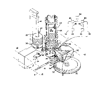
Fig. 1 is a diagrammatic and partly perspective
view of portions of a centrifugal analyzer system in
accordance with the invention;
Fig. 2 is a top plan view of portions of the
analytical and storage compartments of the analyzer
shown in Fig~ l;
Fig. 3 is a sectional view taken along the line
3-3 of Fig. 2;
Fig. 4 is a top plan view of the transfer arm
assembly of the analyzer;
Fig. 5 is a side elevational view of the
transfer arm assembly and portions of its drive
mechanism;
1 3C(3h37
Fig. 6 is a front view of the transfer assembly;
Fig. 7 is a top plan view of the sample storage
chamber coil;
Fig. 8 is a side elevational view of the sample
storage chamber coil shown in Fig. 7;
Fig. 9 is a top plan view of the reagent
- storage chamber coil;
Fig. 10 is a side elevational view of the
reagent storage coil shown in Fig. 9;
Fig. 11 is a top view of the sample and reagent
storage coils in stacked spaced relation;
Fig. 12 is a side elevational view of the
sample and reagent storage coils in stacked spaced
relation;
Fig. 13 is an end view of the stacked coils
shown in top view Fig. 11;
Fig. 14 is a sectional view through the
transfer arm taken along the line 14-14 of Fig. 5;
Fig. 15 is a sectional view of the transfer arm
casting taken along the line 15~15 of Fig. 14;
Fig. 16 is a sectional view taken along the
line 16-16 of Fig. 15;
Fig. 17 is a sectional view taken along the
line 17-17 of'Fig. 6;
Fig. l~-is a sectional view of the clamping
bolt;
Fig. 19 is a side elevational view of the
sample sensor tube;
Fig. 20 is a bottom view of the sensor tube
shown in Fig. 17;
Fig. 21 is a sectional view taken along the
line 21-21 of Fig. 20;
, . . .
1 3C~63,~
7~251-36
~igure 22 is a bo~tom view o~ the sensor ass~mbly
taken alon~ the line 22-22 of Figure 17;
Figure 23 ls a blo~k diagram of control cir~uitry
associated with the transfer assembly; and
Figure 24 is a schematic diagram of the liquid sensor
circuitry.
Description of Particular Embodimen~
With reference to Figures 1-3, the analysis system
there shown is of the centrlfugal type and has analytical
compartment 12 and sample/reagent storage compartment 14 that
are separated hy thermal isolation wall 16 and surrounded by
thermal insulation walls diagrammatically indicated at 18.
Disposed in analytical compartment 12 are a stack of analysis
rotors 20 of the type shown in Canadlan Patent 1,232,g72 which
issued in ~ebruary 9, 1388. Rotors 20 in analytical
ccmpartment 12 are maintained at a precise user specified
analytical temperature o~ 25, 30 or 37~ (plus or minus
0.3C) by a recirculating flow of temperature stabilizqd air
through compartment 12 as de~cribed in ~reater detail in United
States Patent 4,758,8~6 which issued on November 24, 1987.
Storage compartment 14 is maintained at a temperature that is
substantially aooler than analysis compartment, ~or example 14
- 15C Iplus or minus 2C) by a similarly clrculating stream o~
temperature s~abillzed air.
The supply of analysls rotors 20 are stored ln
analysls compartment 12 in spaced stacked relation ln ~eeder.
tower 22. Each rotor 20 provides a clrcum~erentlal array o~
thirty-nine analysi~ cuvettes 24, each of which has two loading
ports 26, 28. The rotors 20 are of a long thermal time
constant ultraviolet tranæmitting plaætic so that the lower
rotors in ~he s~ack in ~eeder tower 22 are at equilibration
- 1 3û~637
72261-36
with the temperature of the analysls compartment 12. Also in
~ompartment 12 i~ loading station 30 at which is disposed an
indexable rotor support table 32 that is indexed by a stepper
motor not shown; analysis station 34 that include~ rotor
support table 36 that is driven in rotation by a DC drive (not
shown); park statlon 38 that includes a fixecl rotor support
table 40; discard stack 42 that includes receiving post 44 on
which used rokors are received; and transport mechanism 46 ~or
transporting rotors 20 from station to station, mechanism
including calliper assembly 48 that has a pair of articulaked
arms that pick up and release rotors 20. Further details oi
this transport and rotor handling system may be had with
reference to United States Patent 4,738,825 which issued on
April 19, 1988.
Disposed in storage compartment 14 is reagent table
50 on which an array of twen~y reagent containers 52 ~each of
twenty milliliters capaci~y) are disposed and moved past
reagent station 54 by an indexing motor (not shown), and
transport ring 56 which holds forty-four one-~uarter milliliter
sample cups 58 and is moved by indexing mechanlsm ~not shown)
past sample station 60. Isolatlon chamber 62 i~ movable
between an operatlve position (as shown in Figure 1) in which
~lange 64 is seated against isolation wall 16 and chamber 62
extends over the reagent and sample stations 54, 60, and a
retracted position in which chamber 62 is retracted into
analysis compartment 12 so that operator access may be obtained
to reagent table 50 and sample ring 56 in storage compartment
14.
Mounted for movement within isolation chamber 62 is
~0 transfer arm mechanism 70 that carries pipette tubes 72, 7~ at
its forward end and has a drlve of the type shown in Uni~ed
~2
~ 6 3 7 72~61-36
Sta~es Patent 4,761,268 which issued on August 2, 1988, for
moving transfer arm 70 between reagent sta~ion s4, sa~ple
s~ation ~0, wash station 76 disposed in isolatlon wall 16, and
loading station 30 where the tips of plpette tubes 72 r 74 are
aligned with cuvette loading ports 26, 28.
Diluent (distilled water) is stored in reservoir 80
that is connected to meterincJ pumps 82, 84 via three way valves
86, 88. Sample metering pump 82 has a capacity of one hundred
microliters and reagent metering pump ~4 has a capacity of two-
hundred flfty microliters, and each metering pump includes apiston that ls driven by a precision stepping motor 9o.
Metering pump 82 is connected to probe 72 through tubing 92 and
cantilever arm 70 and metering pump 84 is connected to probe 74
through tubing 94 and arm 70.
Further detail~ of the reagentt sample, wash and
loading stations may be seen with reference to Figure~ 2 and 3.
Isolation chamber 62 has a series of five aperture port~ 96 in
its bottom wall 98--apertures 96W bein~ allgned with wash
station 76; aper~ure 96S being aligned with sample s~ation 60;
aperture 96R being aligned with reagent station 54; and
aperture 96X being aliyned with the dry well 97 of the reagent
container 52. Transfer arm 70 is moved wlthln isolation
chamber 62 and the probes 72, 74 are inserted through aperture~
96 by the drive mechanism shown in Fi~ure 5. Wash station 76
has two cylindrical wells 93 for recelvlng the tips of pipette
tubes 72, 74, each reagent container 52 has port 95 and dry
well 97; and each sample cup 58 has a port 99.
Further details of pipette transfer assembly 70 may
be seen wi~h reference to Figures 4 and 5. The plpette
transfer ass2mbly includes aluminum castin~ arm 100 that has a
length of about 12.5 centimeter~, a wldth of about 2.3
11
1 3~3637 72261-36
centimeters and a gradua~ed depth to a dimension of about 1/2
centimeter at i~s forward end. Depéndlng portion 102 a~ its
rear end is secured to upstanding drive member 104 by bol~ 106
and dowel pins. The drive mechanism is of the type shown in
the above referenced United States Patent 4,761,263, and
includes support frame 108, stepping mo~or driven lead screw
110 and guide shaft 112. Drive member 104 is pivotally mounted
on support 108 by pivo~ shaft 114 which defines a plvot axis.
Cam follower aperkure 118 of drive member 104 cooperates with
cam 120 that is mounted on shaft 122 that is driven in rotation
by a stepping mo~or (not shown~ to provide an angular lift of
ahout 11 of transport carriage assembly 70 between the solid
line and dotted llne positions shown in Figure 5.
Twenty four ohm silicon insulated heater 130 is
adhesively secured to ~he lower sur~ace of aluminum arm 100 and
connected via leads 132 to terminal block 134 that is mounted
on support board 136 that is secured to arm 100 by fasteners
138, 140. Formed in casting 100 is
1 3~n637
- 13 -
socket 142 (Fig. 5) which receives thermistor 144 (YSI
44032 precision thermistor - 30,000 ohms resistance at
25C.) that is secured to board 136 by stand off 146.
Also mounted on board 136 is voltage regulator 148,
decoupling and power supply capacitors 150, 151, liquid
sensor circuits 152, 154 that are separated by copper
shield 158, and liquid sensor assembly 160. Secured to
the forward end of casting 100 by fasteners 162 (Fig. 6)
is support block 164 which receives collet bolts 166
that clamp pipette tubes 72, 74.
Cast within aluminum arm 100 are sample chamber
coil 170 and reagent chamber coil 172, each of which is
formed of nineteen gauge thin wall stainless steel
tubing. As indicated in Figs. 7 and 8, sample chamber
coil 170 is of single turn configuration and extends
from inlet 174 along inclined transition 175 and
parallel sections 176, 178, 180 to outlet 1~2 and
provides a chamber of about one-hundred microliters
capacity. Reagent coil 172, as shown in Figs. 9 and 10,
is of double turn configuration and extends from inlet
184 through two turns that include parallel lengths 186,
188, 190, 192 and 194 to outlet 196 to provide a chamber
o~ about two-hundred fifty microliters capacity. The
sample and rea~ent coils 170, 172 are purged with
nitrogen, crimped shut, secured in parallel spaced
relation as indicated in Figs. 11 and 12 by spacer
mèmbers 198, disposed in a mold for casting in aluminum
body 100, details of the resulting cast assembly being
shown in Figs. 14 - 16.
Further details of pipette support assembly may
be seen with reference to Figs, 6, 17 and 18. Each
pipette tube 72, 74 is a 3.7 centimeters length of 21
gauge thin wall stainless steel tubing (about 0.8 mm
' ' ' ' ' ' " ' ` " ' ' ~ '" :
j ' Y~
1 ~0,3637
- 14 -
outer diameter). I'wo bores extend through collet block
164, the lower section of each bore being threaZed to
receive collet bolt 166 and having a 45 degree cam
surface 200; and upper portion of the bore being an
enlarged cylinder 202 in which Tygon tube 204 is seated
against smaller diame~er intermediate shoulder 206.
Collet bolt 166, as shown in Fig. 18, has hexagonal head
portion 208, threaded body portion 210 with axially
extending slots 212 that define spaced axially extending
finger portions 214 each of which has a 45 end surface
215, and a through bore 216 in which the stainless steel
pipette tube is disposed with its upper end extending
into Tygon tube 204, as indicated in Fig. 17. Each
pipette tube 72, 74 may be vertically adjusted over a
range of about 0.3 centimeters as compensation for
tolerance build up of the several parts of the pipette
support assembly. Tightening of collet bolt 166 brings
surfaces 200 and 215 into engagement and flexes fingers
214 inwardly to securely clamp the pipette tube. The
upper end of connector tube 204 is received on a
cooperating projecting metal sleeve 218 of the sensor
assembly 160.
Further details of liquid sensor assembly 160
may be seen with reference to Figs. 17 and 19 - 22.
That sensing assembly includes molded urethane housing
230 which supports tubular sample liquid sensor 232 and
~ubular reagent liquid sensor 234- Each liquid sensor
is of the configuration shown in Figs. 19 - 21 and
includes a tube 236 of suitable glass such as Corning
30 B 8870, Corning 8940 or Kimble R6 formed in a semi-circle
of about one centimeter radius with a stainless steel
sleeve 218 adhesively secured at each end of glass tube
aJ/e ~7? c~ Jc s~
1 ~C~6 ~/
- 15 -
236. The tube 236S for sample liquid sensor 232 has an
outer diameter of about 1/2 millimeter, an inner
diameter of about 1/4 millimeter, and defines a volume
of about 1.5 microliters. The tube 236R for reagent
liquid sensor 234 has an outer diameter of about 3/4
millimeter, and a somewhat smaller wall thickness so
that it defines a chamber volume of about six
- microliters. Formed along the semicircular length of
B each tube 236 on opposite sides thereof are silver
electrode plates 240, 242 (DuPont 7713 silver ink), each
of which has an angular extent of about 90 as indicated
in Fig. 21. Capacitor plate 240 extends from plated
cylindrical lead attachment area 244 along a tube length
of about two centimeters with its other end 246 spaced
about 3/4 millimeter from plated lead attachment
cylinder 248 for capacitor electrode 242, the other end
250 of electrode 242 being similarly spaced about 3/4
millimeter from lead attachment cylinder 244. As
indicated in Figs. 17 and ~2, lead 252 (No. 40AWG)
extends from attachment cylinder 244 to connector 254
which protrudes from urethane housing 230 (Figs~ 17 and
22); and a similar lead 256 extends from attachment
cylinder 248 to connector pin 258. Connector pins 254S
and 258S prov,ide ¢onnections via support board 136 to
sample sensor circuit 152 while leads 254R and 258R
provide similar connections to reagent sensor circuit
.154.
Aspects of the control circuitry may be seen
with reference to Fig- 23- In response to temperature
signals from thermistor 144 applied via connect~r 134 to
circuit 268 in system controller 270, circuit 268
produces an output over lines 272 through connector 134
to energize heater 130 and maintain aluminum pipette arm
~ ~QC~ k
. .. , : . , ,
1 3~637
- 16 -
essentially at the temperature of analytical compartment
12. The control circuitry also includes cascaded shift
registers 274, 276; and digital-to-analog converters
278, 2~0. Circuit 282 of controller 270 generates a
serial data train signal over line 284 through buffer
amplifier 286 to shift register 274; and in response to
clock signals on line 288 supplied through buffer 290,
that serial ~ata train is shifted through register 274
and over line 292 to the cascaded shift register 276 to
load shift registers 274, 276 with digital values.
Those digital values specify a sample value that is
applied over lines 294 to digital-to-analog digital
converter 278 and a reagent value that is applied over
lines 296 to digital-to-analog converter 280.
Converter 273 provides an analog output through
amplifier 298 and connector 134 for application to input
300 of sample circuit 152 while the reagent control
signal generated by digital-to-analog converter 280 is
applied through amplifier 298R and connector 134 as
input 300R of reagent circuit 154. Sample sensor
capacitor 232 is connected to circuit 152 through
connectors 254S, 258S and reagent sensor capacitor 232R
is connected to circuit 154 through connectors 254R,
258R. Circuit 152 provides an output on line 302S
through~buffer ~04 to sample indicator circuitry 306 in
controller 270 while circuit 154 produces an output at
terminal 302R through amplifier 308 to reagent indicator
circuitry 310 in controller 270, and circuits 306, 310
may provide outputs to circuit 282 to adjust the sample
and reagent signals being applied to circuits 152, 15~.
Further details of the sample sensor circuitry
may be seen with reference to the schematic diagram of
I 3C',~37
- 17 -
Fig. 24 which shows the sa~ple sensor hybrid integrated
circuit 15~ (the reagent sensoL hybrid inte~rated
circuit 154 being the same). The circuitry includes
voltage controlled oscillator 320 that generates an
unsymmetrical square wave output on line 322, the
duration of the low portion of the square wave output on
line 322 being variable as a function of the analog
voltage applied to input terminal 300 by
digital-to-analog converter 278. The square wave output
on line 322 is applied through inverting comparator 324
and diode 326 to sensor circuitry 330 to which capacitor
232 is connected--in parallel with diode 332 between
input 334 of operational amplifier 336 and output
338--the voltage at input 334 of operational amplifier
336 being controlled by the divider network of resistors
340, 342.
When the output of oscillator 320 on line 322
goes low, diode 326 is forward biased thereby reverse
biasing diode 328. Capacitor 232 charges through
resistor 344 at a rate proportional to its capacitance
value and the output of operational amplifier 336 (on
line 338) ramps downward at a rate inversely
proportional to the value of capacitor 232 from a
voltage of about 19.6 volts (determined by the voltage
provided by divi~er network of resistors 340, 342~.
The output voltage on line 338 is applied to
comparator 346 which has a threshold established by the
divider network of resistors 348 and 350, and when the
voltage at output 338 falls below that value, comparator
344 produces an output on line 352 which conditions the
data input 354 of latch 356.
When the output of oscillator 320 on line 322
goes high, a transition is applied through level
1 ;~C~.637
shifting circuit 358 as a clock pulse to latch 356 to
apply the flip flop data input at terminal 354 as an
output on line 302 updating the liquid information to
controller 270 over line 302. The high output ~rom
oscillato~ 320 is also applied through inverter 324 to
reverse bias diode 326, allowing diode 328 to be forward
biased and establishing a discharge current path for
capacitor 232--capacitor discharging and the voltage at
operational amplifier output 338 increasing until diode
332 becomes forward biased, thus limiting the output
voltage at line 338 to àbout 19.8 volts and
re-establishing the initial condition in the sensor
capacitor 232 at the beginning of each charge cycle.
This circuitry thus provides continuous
monitoring of the fluid in tube 236 of capacitor 232 and
provides signals to controller 270 through buffer 304
(308). The system may establish fixed analog values
that are provided by converters 278, 280 (and thus
monitor the fluid in each capacitor tube for a
particular type - a qualitative-type determination) or
the system may vary the analog value to determine the
type of fluid (a quantitative-type determination) drawn
into the tube during each transfer cycle.
Sample capacitor 232 has a value of about two
picofarads when its tube 220S is filled with air, a
value of about 4.2 picofarads when its tube 220S is
filled with diluent, and a value of about 5.5 picofarads
when its tube 220S is filled with serum; and reagent
capacitor 234 has a capacitance value of about 3.5
microfarads when its tube 220R is filled with air a
value of about 7.7 picofarads when its tube 220S is
filled with diIuent, and a value of about 9.5 picofarads
when its tube is Eilled with reagent. Thus the
'3 '. ` . ,'. '~
` ' ' , ' ' , ' . -~;1'
., ' . . ' , ' - , i
. 4~ .
. . ~ . ` . : . ,,
1 3r~s37
- 19 --
capacitance value of each sensor capacitor increases
significantly when sample liquid or reagent liquid (as
the case may be) is in its tube 220. These capacitance
values are repetitively monitored (at rates in excess of
ten thousand times per second) by measuring the rate at
which the capacitors 232, 234 charge in response to
negative transitions from voltage controlled oscillators
- 320. The frequencies of the square wave output from
oscillators 320 are specified and changed by controller
270 through the shift registers 274, 276 and
digital-to-analOg converters 278, 280, to provide charge
time duration values selected to provide triggering
outputs from comparator 346 to latch 356 that indicate
the type of fluid in the sensor tubes 220S and 220R.
In system operation, drive 110 positions arm
100 at the reagent and sample stations 54, 60 and drive
122 inserts the probe tips into containers 52, 58 at
those stations. The li~uid handling system pumps 82 and
84 draw sample and reagent concurrently through pipettes
72, 74, and the two capacitor sensor tubes 220S, 220R
respectively into the serially connected storage
chambers 172, 174 in the aluminum arm 100 where the
temperatures of the sample and reagent liquids rapidly
increase from the relatively low storage temperature of
compartment 14 to the substantially higher operator
selected temperature (25, 30 or 37~C.) of analytical
compartment 12 so that the aspirated sample and reagent
liquids are rapidly equilibrated to the analytical
temperature during the approximately one second duration
of the movement of the transport arm 70 from the sample
an~ reagent stations 60 and 54 to the loading station 30
where the pipetted volumes of sample and reagent are
dispensed into the analytical cuvette 24 that is at the
1 3 C .~' ~)37
- 20 -
equilibrated temperature of the analytical compartment
12. The cuvette 24 and the reaction constituents thus
are at the analytical temperature when the constitutents
are dispensed into the cuvette (no incubation interval
being required for equilibration) and the transport
calipers 48 may move the loaded analysis rotor from
loading station 30 to analysis station 34 as soon as
filling of the operator specified cuvette regions has
been completed. Should sample or reagent sensor circuit
154 or 156 signal controller 270 that sample liquid or
reagent liquids have not been properly drawn into the
storage chambers, controller 270 terminates or otherwise
reschedules the loading sequence, the aspirated
materials are dispensed into the wash station 76,
i5 pipettes 72, 74 are flushed and the next transfer
sequence is automatically commenced.
While a particular embodiment of the invention
has b`een shown and described, various modifications will
be apparent to those skilled in the art, and therefore
it is not intended that the invention be limited to the
disclosed embodiment, or to details thereof, and
departures may be made therefrom within the spirit and
scope of the invention.
What is claimed is:
,, , . .. , . , .. . ... . . . .. .. ~